Table of Contents
Advertisement
Advertisement
Table of Contents
Troubleshooting

Related Manuals for NEC M362W


Summary of Contents for NEC M362W
- Page 1 Projector M402W/M362W/M322W/ M402X/M362X/M322X/M282X/ M352WS/M302WS/M332XS User’s Manual The M302WS, M402W, M362W, and M362X are not distributed in North America. Model No. NP-M402W, NP-M362W, NP-M322W, NP-M402X, NP-M362X, NP- M322X, NP-M282X, NP-M352WS, NP-M302WS, NP-M332XS...
- Page 2 (3) Great care has been taken in the preparation of this user’s manual; however, should you notice any questionable points, errors or omissions, please contact us. (4) Notwithstanding article (3), NEC will not be responsible for any claims on loss of profit or other matters deemed to result from using the Projector.
-
Page 3: Important Information
Important Information Safety Cautions Precautions Please read this manual carefully before using your NEC projector and keep the manual handy for future reference. CAUTION To turn off main power, be sure to remove the plug from power outlet. The power outlet socket should be installed as near to the equipment as possible, and should be easily accessible. -
Page 4: Important Safeguards
The Federal Communications Commission does not allow any modifications or changes to the unit EXCEPT those specified by NEC Display Solutions of America, Inc. in this manual. Failure to comply with this government regu- lation could void your right to operate this equipment. This equipment has been tested and found to comply with the limits for a Class B digital device, pursuant to Part 15 of the FCC Rules. - Page 5 Important Information WARNING • Do not use any other object than the projector’s sliding lens cover to cover the lens while the projector is on. Doing so can cause the object to get extremely hot, and possibly resulting in a fire or damage due to the heat emitted from the light output.
-
Page 6: Remote Control Precautions
Important Information • Do not place any objects, which are easily affected by heat, in front of a projector exhaust vent. Doing so could lead to the object melting or getting your hands burned from the heat that is emitted from the ex- haust. -
Page 7: Lamp Replacement
Important Information Note for US Residents The lamp in this product contains mercury. Please dispose according to Local, State or Federal Laws. Lamp Replacement • Use the specified lamp for safety and performance. • To replace the lamp, follow all instructions provided on page 132. •... -
Page 8: Power Management Function
Important Information Power management function The projector has power management functions. To reduce power consumption, the power management functions (1 and 2) are factory preset as shown below. To control the projector from an external device via a LAN or serial cable connection, use the on-screen menu to change the settings for 1 and 2. -
Page 9: Table Of Contents
Table of Contents Important Information .................... i 1. Introduction ......................1 ❶ What’s in the Box? ......................1 ❷ Introduction to the Projector ...................2 Congratulations on Your Purchase of the Projector ..........2 Features you’ll enjoy: ....................2 About this user’s manual ...................3 Comparative Table of Main Features ................4 ❸... - Page 10 Table of Contents ❹ Changing Eco Mode/Checking Energy-Saving Effect ..........33 Using Eco Mode [ECO MODE] ................33 Checking Energy-Saving Effect [CARBON METER] ..........34 ❺ Preventing the Unauthorized Use of the Projector [SECURITY] ........35 ❻ Using the Computer Cable (VGA) to Operate the Projector (Virtual Remote Tool) ..38 ❼...
- Page 11 Table of Contents Setting up the Projector for a Wireless LAN Connection (with the optional USB Wireless LAN Unit equipped) [WIRLESS LAN] .............109 ❼ Menu Descriptions & Functions [INFO.] ..............111 [USAGE TIME] ......................111 [SOURCE(1)] ......................112 [SOURCE(2)] ......................112 [WIRED LAN] ......................112 [WIRELESS LAN] ....................113 [VERSION(1)] .......................113 [VERSION(2)] .......................113...
-
Page 12: Introduction
For customers in Europe: You will find our current valid Guarantee Policy on our Web Site: www.nec-display-solutions.com • Important Infomation NEC Projector CD-ROM (For North America: 7N8N4362) User’s manual (PDF) and the (For Other countries than North utility software America: 7N8N4362 and 7N8N4372) (7N952002) •... -
Page 13: ❷ Introduction To The Projector
1. Introduction ❷ Introduction to the Projector This section introduces you to your new projector and describes the features and controls. Congratulations on Your Purchase of the Projector This projector is one of the very best projectors available today. The projector enables you to project precise images up to 300 inches (150 inches for short throw models) across (measured diagonally) from your PC or Mac computer (desktop or notebook), VCR, DVD player, or document camera. -
Page 14: About This User's Manual
• Software programs (User Supportware) contained in the supplied CD-ROM The supplied NEC Projector includes three programs: Virtual Remote Tool, Image Express Utility Lite (for Windows/ Mac OS), PC Control Utility Pro 4 (for Windows)/5 (for Mac OS). Image Express Utility Lite (for Windows) can be started from a commercially available USB memory or SD card without the need of installing on your computer. -
Page 15: Comparative Table Of Main Features
Comparative Table of Main Features The main features vary depending on the model as follows. Standard Models with Wide Panel Standard Models Short-Throw Models Short- with Wide Panel Throw Model M402W M362W M322W M402X M362X M322X M282X M352WS M302WS M332XS Native... -
Page 16: ❸ Part Names Of The Projector
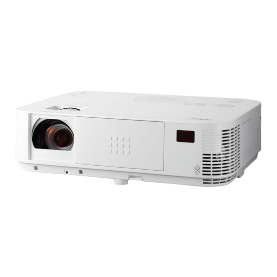
1. Introduction ❸ Part Names of the Projector Front/Top [M402W/M362W/M322W/M402X/M362X/M322X/M282X] Light Sensor (→ page 95) Controls Zoom Lever (→ page 22) (→ page 8) Focus Ring Port Cover for Optional USB (→ page 23) Wireless LAN Unit When using the optional USB... -
Page 17: Rear
1. Introduction Rear [M402W/M362W/M322W/M402X/M362X/M322X/M282X] Lamp Cover (→ page 132) Built-in Security Slot ( Intake Vent (→ page 131) Connection for cable cover (Left) Screw holes (→ page 144) Terminal Panel (→ page 9) Connection for cable cover (Right) Screw holes (→... -
Page 18: Front/Top
1. Introduction Front/Top [M352WS/M302WS/M332XS] Light Sensor (→ page 95) Controls Focus Lever (→ page 8) (→ page 23) Port Cover for Optional USB Wireless LAN Unit When using the optional USB Lens Wireless LAN Unit, first remove the cover. (→ page 129) Lens Cap Adjustable Tilt Foot Security chain opening... -
Page 19: Top Features
1. Introduction Top Features M402W/M362W/M322W/M402X/ M352WS/M302WS/M332XS M362X/M322X/M282X 1, 2 [M352WS/M302WS/M332XS] (POWER) Button 9. ▲▼◀▶ / Volume Buttons ◀▶ / Keystone Buttons (→ page 17, 29) ▲▼ 2. POWER Indicator (→ page 24, 28, 80) (→ page 16, 17, 29, 135) [M402W/M362W/M322W/M402X/M362X/M322X/M282X] 3. -
Page 20: Terminal Panel Features
1. Introduction Terminal Panel Features 1. COMPUTER IN/ Component Input Connector 9. VIDEO AUDIO IN L/MONO, R (RCA) (Mini D-Sub 15 Pin) (→ page 124) (→ page 121, 123, 125) 10. MIC Input Jack (Monaural Mini) 2. COMPUTER AUDIO IN Mini Jack (Stereo Mini) (→... -
Page 21: ❹ Part Names Of The Remote Control
1. Introduction ❹ Part Names of the Remote Control 1. Infrared Transmitter 22. ENTER Button (→ page 11) (→ page 80) 2. POWER ON Button 23. D-ZOOM (+)(–) Button (→ page 17, 29) (→ page 31) 3. STANDBY Button 24. MOUSE L-CLICK Button* (→... -
Page 22: Battery Installation
1. Introduction Battery Installation Press firmly and slide the battery Install new batteries (AAA). Ensure Slip the cover back over the bat- cover off. that you have the batteries’ polarity teries until it snaps into place. Do (+/−) aligned correctly. not mix different types of batteries or new and old batteries. -
Page 23: ❺ Operating Environment For Software Included On Cd-Rom
PC Control Utility Pro 5 (for Mac the computer and the projector are connected with LAN (wired or wireless) or a serial cable. (→ page 54) NOTE: • Image Express Utility Lite does not support "Meeting Mode" in Image Express Utility 2.0 included with our other models. Download service For the update information about these software programs, visit our website: URL: http://www.nec-display.com/dl/en/index.html... -
Page 24: Operating Environment
XGA (1024 × 768) recommended • Windows XP VGA (640 × 480) or higher required XGA (1024 × 768) recommended 1024 dots × 768 lines - 1280 dots × 800 lines recommended (M402W/M362W/ M322W/M352WS/M302WS) Screen Colors High Color (15 bits, 16 bits) True Color (24 bits, 32 bits) (recommended) •... - Page 25 • Apple USB Ethernet adapter “Easy Connection” supports only wireless LAN. Supported Resolution SVGA (800 × 600) or higher required XGA (1024 × 768) recommended (1024 × 768 – 1280 × 800 recommended for M402W/M362W/M322W/ M352WS/M302WS) Supported Screen Colors 16.70 million colors required...
-
Page 26: Projecting An Image (Basic Operation)
2. Projecting an Image (Basic Operation) This section describes how to turn on the projector and to project a picture onto the screen. ❶ Flow of Projecting an Image Step 1 • Connecting your computer / Connecting the power cord (→ page 16) Step 2 •... -
Page 27: ❷ Connecting Your Computer/Connecting The Power Cord
2. Projecting an Image (Basic Operation) ❷ Connecting Your Computer/Connecting the Power Cord 1. Connect your computer to the projector. This section will show you a basic connection to a computer. For information about other connections, see “6. Installation and Connections” on page 121. Connect the computer cable (VGA) between the projector’s COMPUTER IN connector and the computer’s port (mini D-Sub 15 Pin). -
Page 28: ❸ Turning On The Projector
2. Projecting an Image (Basic Operation) ❸ Turning on the Projector 1. Slide the lens cover to the right to uncover the lens. [M352WS/M302WS/M332XS] 1. Remove the lens cap. Lens cap 2. Press the (POWER) button on the projector cabinet or the POWER ON button on the remote control. -
Page 29: Note On Startup Screen (Menu Language Select Screen)
2. Projecting an Image (Basic Operation) Note on Startup screen (Menu Language Select screen) When you first turn on the projector, you will get the Startup menu. This menu gives you the opportunity to select one of the menu languages. To select a menu language, follow these steps: 1. -
Page 30: ❹ Selecting A Source
2. Projecting an Image (Basic Operation) ❹ Selecting a Source Selecting the computer or video source NOTE: Turn on the computer or video source equipment connected to the projector. Detecting the Signal Automatically Press the SOURCE button once.The projector will search for the available input source and display it. The input source will change as follows: COMPUTER →... -
Page 31: ❺ Adjusting The Picture Size And Position
2. Projecting an Image (Basic Operation) ❺ Adjusting the Picture Size and Position Use the adjustable tilt foot, the zoom function or the focus ring to adjust the picture size and position. In this chapter drawings and cables are omitted for clarity. Adjusting the throw angle (the height of an image) Adjusting the left and right tilt of an image [Tilt foot] (→... -
Page 32: Adjust The Tilt Foot
2. Projecting an Image (Basic Operation) Adjust the Tilt Foot 1. Lift the front edge of the projector. CAUTION: Do not try to touch the exhaust vent during Tilt Foot adjustment as it can become heated while the projector is turned on and after it is turned off. -
Page 33: Zoom
2. Projecting an Image (Basic Operation) Zoom [M402X/M362X/M322X/M282X/M402W/M362W/M322W] Use the ZOOM lever to adjust the image size on the screen. Zoom Lever [M332XS/M352WS/M302WS] The image size can be adjusted electronically from the menu. To do so, follow the steps below. -
Page 34: Focus
2. Projecting an Image (Basic Operation) Focus Use the FOCUS ring to obtain the best focus. [M402X/M362X//M322X/M282XM402W/M362W/ M322W] Focus Ring Focus Lever [M332XS/M352WS/M302WS] Use the FOCUS lever to obtain the best focus. -
Page 35: ❻ Correcting Keystone Distortion Manually
2. Projecting an Image (Basic Operation) ❻ Correcting Keystone Distortion Manually If the screen is tilted vertically, keystone distortion becomes large. Automatic Keystone Correction function is turned on at the time of shipment. To correct keystone distortion manually, proceed with the following steps to correct keystone distortion. -
Page 36: Adjusting With The Remote Control
2. Projecting an Image (Basic Operation) Adjusting with the remote control 1. Press the KEYSTONE button. The Keystone bar will be displayed. 2. Use the ◀ or ▶ button to correct the keystone distortion. Adjust so that the right and left sides are parallel. 3. - Page 37 2. Projecting an Image (Basic Operation) [M402W/M362W/M322W/M402X/M362X/M322X/M282X] 1. Press the ▼ ( ) button on the projector cabinet with no menus displayed. The Keystone screen will be displayed on the screen. • Press the KEYSTONE button when using the remote control.
- Page 38 2. Projecting an Image (Basic Operation) 6. After completing Keystone correction, press the EXIT button. The Keystone screen will disappear. • To perform Keystone correction again, press the ▼ button to display the Keystone screen and repeat above steps 1 to 6.
-
Page 39: ❼ Optimizing Computer Signal Automatically
2. Projecting an Image (Basic Operation) ❼ Optimizing Computer Signal Automatically Adjusting the Image Using Auto Adjust Optimizing a computer image automatically. (COMPUTER) Press the AUTO ADJ. button to optimize a computer image automatically. This adjustment may be necessary when you connect your computer for the first time. [Poor picture] [Normal picture] NOTE:... -
Page 40: ❾ Turning Off The Projector
2. Projecting an Image (Basic Operation) ❾ Turning off the Projector To turn off the projector: 1. First, press the (POWER) button on the projector cabinet or the STANDBY button on the remote con- trol. The confirmation message will be displayed. 2. -
Page 41: ❿ After Use
• Remove the USB memory if it is inserted into the projector. 3. Retract adjustable tilt foot if extended. (M402W/M362W/M322W/M402X/M362X/M322X/M282X only) 4. Slide the lens cover to the left to cover the lens. 5. Put the projector and accessories in the supplied soft case. -
Page 42: Convenient Features
3. Convenient Features ❶ Turning off the Image and Sound Press the AV-MUTE button to turn off the image and sound for a short period of time. Press again to restore the image and sound. The projector’s power-saving function will work 10 seconds after the im- age is turned off. - Page 43 3. Convenient Features 2. Press the ▲▼◀▶ button. The area of the magnified image will be moved 3. Press the D-ZOOM (−) button. Each time the D-ZOOM (−) button is pressed, the image is reduced. NOTE: • The image will be enlarged or reduced at the center of the screen. • Displaying the menu will cancel the current magnification.
-
Page 44: ❹ Changing Eco Mode/Checking Energy-Saving Effect
Steady Steady M402W/M402X/M352WS/M332XS and approx. 76% Green light Green light on M362W/M362X/M302WS) The lamp life will extend by lowering the lamp power. [ECO] Lamp power consumption (approx. 60% brightness). The lamp life will extend longer than the one on NOR- MAL mode by controlling power appropriate for the lamp. -
Page 45: Checking Energy-Saving Effect [Carbon Meter]
3. Convenient Features Checking Energy-Saving Effect [CARBON METER] This feature will show energy-saving effect in terms of CO emission reduction (kg) when the projector’s [ECO MODE] is set to [AUTO ECO], [NORMAL], or [ECO]. This feature is called as [CARBON METER]. There are two messages: [TOTAL CARBON SAVINGS] and [CARBON SAVINGS-SESSION]. -
Page 46: ❺ Preventing The Unauthorized Use Of The Projector [Security]
3. Convenient Features ❺ Preventing the Unauthorized Use of the Projector [SECURITY] A keyword can be set for your projector using the Menu to avoid operation by an unauthorized user. When a keyword is set, turning on the projector will display the Keyword input screen. Unless the correct keyword is entered, the pro- jector cannot project an image. - Page 47 3. Convenient Features 7. Type in the same combination of ▲▼◀▶ buttons and press the ENTER button. The confirmation screen will be displayed. 8. Select [YES] and press the ENTER button. The SECURITY function has been enabled. To turn on the projector when [SECURITY] is enabled: 1.
- Page 48 3. Convenient Features To disable the SECURITY function: 1. Press the MENU button. The menu will be displayed. 2. Select [SETUP] → [INSTALLATION] → [SECURITY] and press the ENTER button. The OFF/ON menu will be displayed. 3. Select [OFF] and press the ENTER button. The SECURITY KEYWORD screen will be displayed.
-
Page 49: ❻ Using The Computer Cable (Vga) To Operate The Projector (Virtual Remote Tool)
❻ Using the Computer Cable (VGA) to Operate the Projector (Virtual Remote Tool) Using the utility software “Virtual Remote Tool” included on the companion NEC Projector CD-ROM, Virtual Remote screen (or toolbar) can be displayed on your computer screen. This will help you perform operations such as projector’s power on or off and signal selection via the computer cable (VGA), serial cable, or LAN connection. - Page 50 • To run Virtual Remote Tool on Windows 8 and Windows XP, “Microsoft .NET Framework Version 2.0” is required. The Microsoft .NET Framework Version 2.0, 3.0 or 3.5 is available from Microsoft’s web page. Download and install the it on your computer. TIP: • The projector’s COMPUTER IN connector supports DDC/CI (Display Data Channel Command Interface). DDC/CI is a standard interface for bidirectional communication between display/projector and computer. Step 1: Install Virtual Remote Tool on the computer NOTE: • To install Virtual Remote Tool, the Windows user account must have “Administrator” privilege (Windows 8, Windows 7, Windows Vista and Windows XP). • Exit all running programs before installing Virtual Remote Tool. If another program is running, the installation may not be com- pleted. 1 Insert the accompanying NEC Projector CD-ROM into your CD-ROM drive. The menu window will be displayed.
- Page 51 3. Convenient Features TIP: If the menu window will not be displayed, try the following procedure. For Windows 7 1. Click “start” on Windows. 2. Click “All Programs” → “Accessories” → “Run”. 3. Type your CD-ROM drive name (example: “Q:\”) and “LAUNCHER.EXE” in “Name”. (example: Q:\ LAUNCHER.EXE) 4. Click “OK”. The menu window will be displayed. 2 Click “Install Virtual Remote Tool”...
- Page 52 3. Convenient Features TIP: Uninstalling Virtual Remote Tool Preparation: Exit Virtual Remote Tool before uninstalling. To uninstall Virtual Remote Tool, the Windows user account must have “Administrator” privilege (Windows 8, Windows 7 and Windows Vista) or “Computer Administrator” privilege (Windows XP).
- Page 53 Windows Desktop. Start from the Start menu • Click [Start] → [All Programs] or [Programs] → [NEC Projector User Supportware] → [Virtual Remote Tool] → [Virtual Remote Tool]. When Virtual Remote Tool starts for the first time, “Easy Setup” window will be displayed.
- Page 54 The Help screen will be displayed. • Displaying the help file using the Start Menu. 1. Click “Start” → “All programs” or “Programs” → “NEC Projector User Supportware” → “Virtual Remote Tool” → and then “Virtual Remote Tool Help” in this order.
-
Page 55: ❼ Operating Your Computer's Mouse Functions From The Projector's Remote Control
3. Convenient Features ❼ Operating Your Computer’s Mouse Functions from the Projector’s Remote Control via the USB Cable (Remote Mouse Function) The built-in remote mouse function enables you to operate your computer’s mouse functions from the supplied remote control when the projector is connected to a computer via a commercially available USB cable (compatible with USB 2.0 specifications). -
Page 56: (Usb Display)
Power On/Off and source selection of the projector can be done from your computer without connecting a computer cable (VGA). NOTE: • To make USB DISPLAY available on Windows 8, Windows 7, Windows Vista and Windows XP, the Windows user account must have “Administrator” privilege. • USB Display uses functions of Image Express Utility Lite contained on NEC Projector CD-ROM (→ page 58). Starting USB Display, however, will not install Image Express Utility Lite on your computer. This is because USB Display executes the projector’s program only. • When Image Express Utility Lite is installed to both your computer and the projector, the one installed to your computer always start even if it is older version than the one installed to the projector. - Page 57 3. Convenient Features 5. Operate the control window. (Source) ����� Selects an input source of the projector� (Picture) ���� Turns on or off AV-MUTE (Picture mute), and turns on or off FREEZE (Freeze a picture), and Geometric Correction Tool (GCT) functions� (Sound) �����...
-
Page 58: ❾ Controlling The Projector By Using An Http Browser
• Start the Web browser on the computer via the network connected to the projector and enter the following URL : http://<the projector’s IP address> /index.html • Use Image Express Utility Lite contained on the supplied NEC Projector CD-ROM. TIP: The factory setting IP address is [DHCP ON]. NOTE: • To use the projector in a network, consult with your network administrator about network settings. -
Page 59: Handling Of The Address For Operation Via A Browser
IP address of the projector has been set in the “HOSTS” file of the computer being used. Example 1: When the host name of the projector has been set to “pj.nec.co.jp”, access is gained to the network setting by specifying http://pj.nec.co.jp/index.html... - Page 60 3. Convenient Features PICTURE: Controls the video adjustment of the projector. BRIGHTNESS ▲ ���� Increases the brightness adjustment value� BRIGHTNESS ▼ ���� Decreases the brightness adjustment value� CONTRAST ▲ �������� Increases the contrast adjustment value� CONTRAST ▼ �������� Decreases the contrast adjustment value� COLOR ▲...
-
Page 61: Network Settings
3. Convenient Features NETWORK SETTINGS • SETTINGS WIRED or WIRELESS SETTING Set for wired LAN or for wireless LAN. APPLY Apply your settings to wired LAN or wireless LAN. DHCP ON Automatically assign IP address, subnet mask, and gateway to the projector from your DHCP server. - Page 62 3. Convenient Features NETWORK TYPE Select communication method when using wireless LAN. INFRASTRUCTURE: Select this option when communicating with one or more equip- ment connected to the wireless LAN network via a wireless access point. AD HOC: Select this option when using the wireless LAN to directly communicate with a computer in peer-to-peer mode.
- Page 63 Clearing a checkmark will turn off the Alert Mail feature. Sample of a message to be sent from the projector: The lamp is at the end of its usable life. Please replace the lamp. Projector Name: NEC Projector Lamp Hours Used: 100 [H] SENDER’S ADDRESS Enter sender’s address.
- Page 64 3. Convenient Features CRESTRON ROOMVIEW compatibility The projector supports CRESTRON ROOMVIEW, allowing multiple devices connected in the network to be managed and controlled from a computer or a controller. For more information, visit http://www.crestron.com <Setting Procedure> Access to the HTTP server function, and make necessary settings for [CRESTRON] in [NETWORK SETTINGS]. •...
-
Page 65: ❿ Controlling The Projector Over A Lan (Pc Control Utility Pro 4/Pro 5)
❿ Controlling the Projector over a LAN (PC Control Utility Pro 4/ Pro 5) Using the utility software “PC Control Utility Pro 4” and “PC Control Utility Pro 5” included on the companion NEC Projector CD-ROM, the projector can be controlled from a computer over a LAN. - Page 66 3. Convenient Features TIP: If the menu window will not be displayed, try the following procedure. For Windows 7: 1. Click “start” on Windows. 2. Click “All Programs” → “Accessories” → “Run”. 3. Type your CD-ROM drive name (example: “Q:\”) and “LAUNCHER.EXE” in “Name”. (example: Q:\ LAUNCHER.EXE) 4. Click “OK”. the menu window will be displayed. 2 Click “PC Control Utility Pro 4”...
- Page 67 Wireless LAN (Optional: NP02LM series)” (→ page 128) and “9. Controlling the Projector by Using an HTTP Browser” (→ page 47) Step 3: Start PC Control Utility Pro 4 Click “Start” → “All programs” or “Programs” → “NEC Projector User Supportware” → “PC Control Utility Pro 4” → “PC Control Utility Pro 4”. NOTE: • For the Schedule function of the PC Control utility Pro 4 to work, you must have your computer running and not in standby/...
- Page 68 Using on Mac OS Step 1: Install PC Control Utility Pro 5 on the computer 1. Insert the accompanying NEC Projector CD-ROM in your Mac CD-ROM drive. The CD-ROM icon will be displayed on the desktop. 2. Double-click the CD-ROM icon.
-
Page 69: ⓫ Projecting Your Computer's Screen Image From The Projector Over A Lan
Projector over a LAN (Image Express Utility Lite) Using Image Express Utility Lite contained on the supplied NEC Projector CD-ROM allows you to send the computer’s screen image and sound to the projector over a USB cable or a wired or wireless LAN. - Page 70 • To install or uninstall the program, the Windows user account must have “Administrator” privilege (Windows 8, Windows 7, Windows Vista and Windows XP). • Exit all running programs before installation. If another program is running, the installation may not be completed. • Image Express Utility Lite will be installed to the system drive of your computer. If the message “There is not enough free space on destination” is displayed, free up enough space (about 100 MB) to install the program. 1. Insert the accompanying NEC Projector CD-ROM into your CD-ROM drive. The menu window will be displayed. TIP: If the menu window will not be displayed, try the following procedure. For Windows 7: 1. Click “start” on Windows. 2. Click “All Programs” → “Accessories” → “Run”.
- Page 71 The Help screen will be displayed. • Displaying the help file using the Start Menu. Click “Start” → “All programs” or “Programs” → “NEC Projector User Supportware” → “Image Express Utility Lite” → “Image Express Utility Lite Help”. The Help screen will be displayed.
-
Page 72: Starting Image Express Utility Lite From A Usb Memory Or Sd Card
1. Copy Image Express Utility Lite to removable media. Copy all the folders and files (total size approx. 6MB) from the “IEU_Lite (removable-media)” folder in the supplied NEC Projector CD-ROM to the root directory of your removable media. 2. Insert your removable media into your computer. -
Page 73: Downloading Image Express Utility Lite Via The Http Server
3. Convenient Features Downloading Image Express Utility Lite via the HTTP server Downloading procedure when the projector is connected to the Internet. 1. Access the HTTP server. (→ page 47) 2. Select the “NETWORK SETTINGS” tab and then the “NETWORK SERVICE” tab. 3. - Page 74 Using on Mac OS Step 1: Install Image Express Utility Lite for Mac OS on the computer 1. Insert the accompanying NEC Projector CD-ROM in your Mac CD-ROM drive. The CD-ROM icon will be displayed on the desktop. 2. Double-click the CD-ROM icon.
- Page 75 3. Convenient Features TIP: Viewing the Help of Image Express Utility Lite for Mac OS • From the menu bar, click “Help” → “Image Express Utility Lite Help” while Image Express Utility is run- ning. The Help screen will be displayed...
-
Page 76: ⓬ Projecting An Image From An Angle
3. Convenient Features ⓬ Projecting an Image from an Angle (Geometric Correction Tool in Image Express Utility Lite) The Geometric Correction Tool (GCT) function allows you to correct distortion of images projected even from an angle. What you can do with GCT •... - Page 77 3. Convenient Features 3. Use the mouse to click the [ • ] mark of which corner you wish to move. The currently selected [ • ] mark will turn red. (In the above example, Windows screens are omitted for clarification.) 4.
-
Page 78: ⓭ Viewing 3D Images
Also refer to the user’s manual accompanied with your LCD shutter eyeglasses for more information. On-screen menu for 3D images Follow the steps to display the 3D menu. 1. Press the MENU button. The on-screen menu will be displayed. 2. Press the ▷ button twice. The [SETUP] menu will be displayed. [M402W/M362W/M322W/M402X/M362X/M322X/ [M352WS/M302WS/M332XS] M282X]... - Page 79 3. Convenient Features 3. Press the ▽ button once, and then press the ▷ button five times. The [3D] menu will be displayed 4. Press the ▽ button to select a signal and press the ENTER button. The 3D (DETAIL SETTINGS) screen will be displayed. 5.
- Page 80 3. Convenient Features To view 3D images, see page 67. Select [COMPUTER], [HDMI1], [HDMI2], or [VIDEO]. NOTE: • The maximum distance for viewing 3D images is 10 m/394 inches from the screen surface under the following restrictions: - Brightness on the projector: 2000 lumens or greater - Screen gain: 1 - Viewing position: Facing straight towards the screen center - Outside light: None - LCD shutter eyeglasses: DLP Link compatible 3D eyeglasses ® • If 3D content is played back on your computer and the performance is poor it may be caused by the CPU or graphics chip. In this case you may have difficulty seeing the 3D images as they were intended. Check to see if your computer meets the requirements provided in your user’s manual included with your 3D content. • The DLP Link compatible LCD shutter eyeglasses allow you to view 3D images by receiving synch signals, which are included ® in left eye and right eye images, reflected from the screen. Depending on environments or conditions such as the ambient bright- ness, screen size or viewing distance, the LCD shutter eyeglasses may fail to receive synch signals, causing poor 3D images.
- Page 81 3. Convenient Features Troubleshooting on viewing 3D images If images will not be displayed in 3D or 3D images appear as 2D, check the following table. Also refer to the user’s manual accompanied with your 3D content or LCD shutter eyeglasses. Possible causes Solutions •...
-
Page 82: ⓮ Connecting Your Microphone
3. Convenient Features ⓮ Connecting Your Microphone Connecting a commercially available dynamic or condenser microphone to the MIC input jack allows you to output your mic sound from the built-in speaker. Sound from COMPUTER, HDMI 1, HDMI 2, and VIDEO audio inputs or sound of USB-A/LAN input will be heard from the speaker with your microphone voice. -
Page 83: Using The Viewer
4. Using the Viewer ❶ What you can do with the Viewer The Viewer has the following features. • When a commercially available USB memory that stores image files is inserted into the USB-A port (Type A) of the projector, the Viewer allows you to view the image files on the USB memory. Even if no computer is available, presentations can be conducted simply with the projector. - Page 84 4. Using the Viewer NOTE • The USB-A port of the projector does not support USB hub. • The following operations by using the buttons on the projector are not possible when the VIEWER screen such as the slide screen and the thumbnail screen is displayed. - Keystone correction by using the ▲/▼ button - Auto Adjustment by using the AUTO ADJ. button - Volume control with the ◀ or ▶ button To perform Keystone correction or Source selection during display of the Viewer, press the MENU button twice to display the menu and operate Viewer from the menu. • Freezing picture by using the FREEZE button on the remote control is not possible when the VIEWER screen such as the slide screen and the thumbnail screen is displayed. • Executing [RESET] → [ALL DATA] from the menu will return the settings for the Viewer toolbar to the factory default. • USB memory - Be sure to use a USB memory device formatted with the FAT32 or FAT16 file system. The projector does not support NTFS formatted USB memory. If the projector does not recognize your USB memory, check if the format is supported. To format your USB memory in your computer, refer to the document or help file that comes with your Windows. - We do not warrant that the USB-A port of the projector will support all USB memories in the market. • Supported images - Supported file format for Viewer are as follows. We do not warrant all the images are supported for Viewer. Images other than mentioned in the table may not be supported. Image type Extension Description JPEG...
-
Page 85: ❷ Projecting Images Stored In A Usb Memory Device
4. Using the Viewer ❷ Projecting images stored in a USB memory device This section explains the basic operation of the Viewer. The explanation provides the operational procedure when the Viewer toolbar (→ page 78) is set to the factory de- fault. - Page 86 4. Using the Viewer 4. Press the ENTER button. The thumbnail screen will be displayed. (→ page 77) 5. Use the ▲▼◀ or ▶ button to select an icon. • The → (arrow) symbol on the right indicates there are more pages.
-
Page 87: Exiting The Viewer
4. Using the Viewer Removing the USB memory from the projector 1. Select the VIEWER start screen. Press the EXIT button with no menu displayed. 2. Remove the USB memory from the projector. Make sure that the LED on the USB memory is not flashing before removing the USB memory. - Page 88 • The maximum number of image files or folders within one page is different depending on the model. M402X/M362X/M322X/M282X/M332XS are 5 by 4 M402W/M362W/M322W/M352WS/M302WS are 6 by 4 The cursor is used to select (highlight) the folder or image file by using ▲▼◀▶ but- (4) Cursor ton.
-
Page 89: Using The Toolbar
4. Using the Viewer Using the toolbar 1. Press the MENU button. The toolbar will be displayed. The SOURCE screen will be displayed as Viewer connection screen. 2. Use the ◀ or ▶ button to select an item and use the ▲ or ▼ button to select its available option. When the cursor is placed, the selected item will be changed to yellow. - Page 90 4. Using the Viewer Slide toolbar Menu Options Description (1) Display Closes the menu and switches to the slide screen. Closes the menu and displays the thumbnail screen. Closes the menu and starts the slideshow from the highlighted item. (2) Image Closes the menu and displays the image in its actual size.
-
Page 91: Using On-Screen Menu
5. Using On-Screen Menu ❶ Using the Menus NOTE: The on-screen menu may not be displayed correctly while interlaced motion video image is projected. 1. Press the MENU button on the remote control or the projector cabinet to display the menu. NOTE: The commands such as ENTER, EXIT, ▲▼, ◀▶ in the bottom show available buttons for your operation. 2. Press the ◀▶ buttons on the remote control or the projector cabinet to display the submenu. 3. -
Page 92: ❷ Menu Elements
5. Using On-Screen Menu ❷ Menu Elements Slide bar Solid triangle Available buttons Source Highlight Radio button Wireless symbol ECO mode symbol Off Timer remaining High Altitude symbol time Thermometer symbol Key Lock symbol Menu windows or dialog boxes typically have the following elements: Highlight �����������������������������Indicates the selected menu or item�... -
Page 93: ❸ List Of Menu Items
AUTO AUTO, OFF, ON IMAGE M402X/M362X/M322X/M282X/M332XS: AUTO, 4:3, 16:9, OPTIONS 15:9, 16:10, WIDE ZOOM, NATIVE ASPECT RATIO M402W/M362W/M322W/M352WS/M302WS: AUTO, 4:3, 16:9, 15:9, 16:10, LETTERBOX, NATIVE POSITION (Not available on M402W/ −16 to 16 M362W/M322W/M352WS/M302WS) NOISE REDUCTION OFF, LOW, MEDIUM, HIGH... - Page 94 AUTO, HIGH, HIGH ALTITUDE AUTO, NTSC3.58, NTSC4.43, PAL, PAL-M, PAL-N, PAL60, COLOR SYSTEM VIDEO AUTO SECAM M402X/M362X/ M322X/M282X/ M332XS: OFF WXGA MODE OFF, ON M402W/M362W/ M322W/M352WS/ M302WS: ON OPTIONS(1) HDMI1 VIDEO LEVEL NORMAL AUTO, NORMAL, ENHANCED HDMI SETTINGS HDMI2 VIDEO LEVEL...
- Page 95 5. Using On-Screen Menu Menu Item Default Options LAMP LIFE REMAINING LAMP HOURS USED USAGE TIME TOTAL CARBON SAVINGS TOTAL COST SAVINGS RESOLUTION HORIZONTAL FREQUENCY VERTICAL FREQUENCY SOURCE(1) SYNC TYPE SYNC POLARITY SCAN TYPE SIGNAL TYPE VIDEO TYPE SOURCE(2) BIT DEPTH VIDEO LEVEL 3D SIGNAL IP ADDRESS...
-
Page 96: ❹ Menu Descriptions & Functions [Source]
5. Using On-Screen Menu ❹ Menu Descriptions & Functions [SOURCE] COMPUTER Selects the computer connected to your COMPUTER input connector signal. NOTE: When the component input signal is connected to the COMPUTER IN connector, select [COMPUTER] respectively. HDMI1 and 2 Selects the HDMI compatible equipment connected to your HDMI 1 or HDMI 2 IN connector. VIDEO Selects what is connected to your VIDEO input-VCR, DVD player or document camera. -
Page 97: ❺ Menu Descriptions & Functions [Adjust]
5. Using On-Screen Menu ❺ Menu Descriptions & Functions [ADJUST] [PICTURE] [PRESET] This function allows you to select optimized settings for your projected image. You can adjust neutral tint for yellow, cyan or magenta. There are seven factory presets optimized for various types of images. You can also use [DETAIL SETTINGS] to set user adjustable settings to customize each gamma or color. - Page 98 5. Using On-Screen Menu Storing Your Customized Settings [REFERENCE] This function allows you to store your customized settings in [PRESET 1] to [PRESET 7]. First, select a base preset mode from [REFERENCE], then set [GAMMA CORRECTION], [SCREEN SIZE], [COLOR TEMPERATURE], [COLOR ENHANCEMENT], and [DYNAMIC CONTRAST]. HIGH-BRIGHT ��������...
- Page 99 5. Using On-Screen Menu [CONTRAST] Adjusts the intensity of the image according to the incoming signal. [BRIGHTNESS] Adjusts the brightness level or the back raster intensity. [SHARPNESS] Controls the detail of the image. [COLOR] Increases or decreases the color saturation level. [HUE] Varies the color level from +/−...
-
Page 100: [Image Options]
5. Using On-Screen Menu [IMAGE OPTIONS] Adjusting Clock and Phase [CLOCK/PHASE] This allows you to manually adjust CLOCK and PHASE. CLOCK ������������������� Use this item to fine tune the computer image or to remove any vertical banding that might appear� This function adjusts the clock frequencies that eliminate the horizontal banding in the image�... - Page 101 5. Using On-Screen Menu Adjusting Horizontal/Vertical Position [HORIZONTAL/VERTICAL] Adjusts the image location horizontally and vertically. NOTE: The [HORIZONTAL] and [VERTICAL] items are not available for VIDEO, HDMI1, HDMI2, USB-A, LAN, and USB-B. - An image can be distorted during the adjustment of [CLOCK] and [PHASE]. This is not malfunction. - The adjustments for [CLOCK], [PHASE], [HORIZONTAL], and [VERTICAL] will be stored in memory for the current signal.
- Page 102 800 × 600 is displayed on the M402X/ M362X/M322X/M282X/M332XS: [Example 2] When the incoming sig- nal with the resolution of 800 × 600 is displayed on the M402W/M362W/ M322W/M352WS/M302WS: NOTE: • When a non-computer signal is displayed, the [NATIVE] is not available. • When a signal with a higher resolution than the projector’s native resolution is displayed, [NA- TIVE] is not available.
- Page 103 The letterbox signal has aspect ratios with the vista size “1.85:1” or cinema scope size “2.35:1” for movie film. • The term “squeeze” refers to the compressed image of which aspect ratio is converted from 16:9 to 4:3. Adjusting the Vertical Position of Image [POSITION] (not available on M402W/M362W/M322W/ M352WS/M302WS) (only when [16:9], [15:9], or [16:10] is selected for [ASPECT RATIO]) When [16:9], [15:9], or [16:10] is selected in [ASPECT RATIO], the image is displayed with black borders on the top and bottom.
- Page 104 5. Using On-Screen Menu Turning on Noise Reduction [NOISE REDUCTION] This function allows you to select the level of noise reduction. The projector is set to the optimized level for each signal at the factory. Select your preference item for your signal when video noise is noticeable. The options are [OFF], [LOW], [MEDIUM], and [HIGH].
-
Page 105: ❻ Menu Descriptions & Functions [Setup]
5. Using On-Screen Menu ❻ Menu Descriptions & Functions [SETUP] [GENERAL] [M402W/M362W/M322W/M402X/M362X/M322X/ [M352WS/M302WS/M332XS] M282X] Using Digital Zoom [DIGITAL ZOOM] (M352WS/M302WS/M332XS) This feature allows you to electronically fine adjust the image size on the screen. Use the ◀ or ▶ button to large or reduce the projected image. - Page 106 5. Using On-Screen Menu Using the Wall Color Correction [WALL COLOR] This function allows for quick adaptive color correction in applications where the screen material is not white. NOTE: • Selecting [WHITEBOARD] reduces lamp brightness. • The [WALL COLOR] item cannot be selected when [ON] is selected for [3D] while images are projected. Setting various items related to lamp brightness [ECO SETTINGS] This option allows you to decrease the power consumption or to prolong the lamp life by controlling the lamp bright- ness.
- Page 107 5. Using On-Screen Menu ECO OPTION Set the option when [ECO] is selected for [ECO MODE]. CONSTANT BRIGHTNESS: OFF ������������������������ The CONSTANT BRIGHTNESS feature will not work� The lamp brightness will gradually decrease over long periods of time� ON ������������������������� The lamp brightness will increase according to the lamp use of time and will be kept at the lamp brightness equivalent to the brightness at ECO�...
-
Page 108: [Menu]
5. Using On-Screen Menu [MENU] Selecting Menu Color [COLOR SELECT] You can choose between two options for menu color: COLOR and MONOCHROME. Turning On / Off Source Display [SOURCE DISPLAY] This option turns on or off input name display such as COMPUTER, HDMI1, HDMI2, VIDEO, USB-A, LAN, USB-B, to be displayed on the top right of the screen. - Page 109 5. Using On-Screen Menu Selecting Menu Display Time [DISPLAY TIME] This option allows you to select how long the projector waits after the last touch of a button to turn off the menu. The preset choices are [MANUAL], [AUTO 5 SEC], [AUTO 15 SEC], and [AUTO 45 SEC]. The [AUTO 45 SEC] is the fac- tory preset.
-
Page 110: [Installation]
5. Using On-Screen Menu [INSTALLATION] Selecting Projector Orientation [ORIENTATION] This reorients your image for your type of projection. The options are: desktop front projection, ceiling rear projection, desktop rear projection, and ceiling front projection. DESKTOP FRONT CEILING REAR DESKTOP REAR CEILING FRONT Disabling the Cabinet Buttons [CONTROL PANEL LOCK] This option turns on or off the CONTROL PANEL LOCK function. - Page 111 5. Using On-Screen Menu Selecting Communication Speed [COMMUNICATION SPEED] This feature sets the baud rate of the PC Control port (D-Sub 9P). It supports data rates from 4800 to 38400 bps. The default is 38400 bps. Select the appropriate baud rate for your equipment to be connected (depending on the equip- ment, a lower baud rate may be recommended for long cable runs).
-
Page 112: [Options(1)]
5. Using On-Screen Menu Using Test Pattern [TEST PATTERN] Displays the test pattern to check for image distortion at the time of the projector setup. Press the ENTER button to display the test pattern; press the EXIT button to close the test pattern and return to the menu. Menu operation and keystone correction are not possible when the test pattern is displayed. - Page 113 M402X/M362X/M322X/M282X/M332XS. In this case, select [OFF]. NOTE: • The [OFF] is selected at the time of shipment of M402X/M362X/M322X/M282X/M332XS. • The [ON] is selected at the time of shipment of M402W/M362W/M322W/M352WS/M302WS. Setting HDMI1/2 [HDMI SETTINGS] Make the settings for each video level when connecting HDMI equipment such as a DVD player. VIDEO LEVEL ��������� Select [AUTO] to automatically detect video level� If automatic detection may not work well, select [NOR- MAL] to disable the [ENHANCED] feature of your HDMI equipment or select [ENHANCED] to improve image contrast and increase detail in the dark areas�...
-
Page 114: [Options(2)]
5. Using On-Screen Menu [OPTIONS(2)] Selecting Standby condition in [STANDBY MODE] The projector has two standby modes: [NORMAL] and [NETWORK STANDBY]. The [NORMAL] mode is the mode that allows you to put the projector in the power-saving condition which consumes less power than the [NETWORK STANDBY] mode. - Page 115 5. Using On-Screen Menu Turning On the Projector By Applying Computer Signal [AUTO POWER ON(COMP.)] When the projector is in Standby mode, applying a computer signal from a computer connected to the COMPUTER IN input will power on the projector and simultaneously project the computer’s image. This functionality eliminates the need to always use the POWER button on the remote control or the projector cabinet to power on the projector.
- Page 116 5. Using On-Screen Menu Setting carbon footprint factor [CARBON CONVERT] Adjusts the carbon footprint factor in the carbon saving calculation. The initial setting is 0.505[kg-CO2/kWh] based on the CO2 Emissions from Fuel Combustion (2008 Edition) published by OECD. Selecting your currency [CURRENCY] Displays electricity pricing (available in 4 currency units).
-
Page 117: [3D]
5. Using On-Screen Menu [3D] Selecting input connected to a source of 3D images [COMPUTER/HDMI1/HDMI2/VIDEO] [3D] This function switches the 3D mode between ON and OFF for each input. ON ������������������������� Turns on the 3D mode for the selected input� NOTE: To confirm that the supported 3D signal is accepted, use either way of the following: • Make sure that [3D] is displayed in the top right of the screen after the source is selected. - Page 118 5. Using On-Screen Menu [L/R INVERT] Change the setting if you have difficulty seeing 3D images. NON-INVERT ��������� Normal setting� INVERT ������������������ Changes the order of displaying the images for left eye and right eye� NOTE: This option is available only when [DLP Link] is selected for [GLASSES]. ®...
-
Page 119: Setting Up The Projector For A Wired Lan Connection [Wired Lan]
5. Using On-Screen Menu Setting up the Projector for a Wired LAN Connection [WIRED LAN] Important • Consult with your network administrator about these settings. • When using a wired LAN connection, connect a LAN cable (Ethernet cable) to the LAN port (RJ-45) of the projec- tor. -
Page 120: Setting Up The Projector For A Wireless Lan Connection (With The Optional Usb Wireless Lan Unit Equipped) [Wirless Lan]
Wireless LAN connection will be turned off [EASY CONNECTION] Select [EASY CONNECTION] to execute a wireless LAN easily using Image Express Utility Lite on the supplied NEC Projector CD-ROM. [SIMPLE ACCESS Set the projector for simple access point. Selecting [SIMPLE ACCESS POINT] will allow the projec- POINT] tor to create an infrastructure network. - Page 121 Express Utility Lite and connecting the PC and projector via a wireless LAN. The Image Express Utility Lite is contained on the supplied NEC Projector CD-ROM. To use [EASY CONNECTION], access the HTTP server function to display the web browser (→ page 47) and select [NETWORK SETTINGS] →...
-
Page 122: ❼ Menu Descriptions & Functions [Info.]
NORMAL AUTO ECO NORMAL M402W 3500H 3500H to 5000H 8000H 100% OFF thru Approx. 81% Approx. 60% M402X 6000H M352WS M332XS M362W 3500H 3500H to 5000H 8000H Approx. 74% M362X 6500H M322W 3500H 3500H to 5500H 8000H Approx. 76% M322X... -
Page 123: [Source(1)]
5. Using On-Screen Menu [SOURCE(1)] [RESOLUTION] [HORIZONTAL FREQUENCY] [VERTICAL FREQUENCY] [SYNC TYPE] [SYNC POLARITY] [SCAN TYPE] [SOURCE(2)] [SIGNAL TYPE] [VIDEO TYPE] [BIT DEPTH] [VIDEO LEVEL] [3D SIGNAL] [WIRED LAN] [IP ADDRESS] [SUBNET MASK] [GATEWAY] [MAC ADDRESS]... -
Page 124: [Wireless Lan]
5. Using On-Screen Menu [WIRELESS LAN] [IP ADDRESS] [SUBNET MASK] [GATEWAY] [MAC ADDRESS] [SSID] [NETWORK TYPE] [WEP/WPA] [CHANNEL] [SIGNAL LEVEL] [VERSION(1)] [FIRMWARE] Version [DATA] Version [VERSION(2)] [FIRMWARE2] Version... -
Page 125: [Others]
5. Using On-Screen Menu [OTHERS] [PROJECTOR NAME] [MODEL NO.] [SERIAL NUMBER] [LAN UNIT TYPE] [CONTROL ID] (when [CONTROL ID] is set) -
Page 126: ❽ Menu Descriptions & Functions [Reset]
5. Using On-Screen Menu ❽ Menu Descriptions & Functions [RESET] Returning to Factory Default [RESET] The RESET feature allows you to change adjustments and settings to the factory preset for a (all) source (s) except the following: [CURRENT SIGNAL] Resets the adjustments for the current signal to the factory preset levels. The items that can be reset are: [PRESET], [CONTRAST], [BRIGHTNESS], [COLOR], [HUE], [SHARPNESS], [ASPECT RATIO], [HORIZONTAL], [VERTICAL], [CLOCK], [PHASE], [OVERSCAN], [NOISE REDUCTION], and [TELECINE]. -
Page 127: Installation And Connections
6. Installation and Connections This section describes how to set up your projector and how to connect video and audio sources. Your projector is simple to set up and use. But before you get started, you must first: ① Set up a screen and the projector. ②... - Page 128 6. Installation and Connections [M402W/M362W/M322W] The further your projector is from the screen or wall, the larger the image. The minimum size the image can be is approximately 30" (0.76 m) measured diagonally when the projector is roughly 41 inches (1.0 m) from the wall or screen.
- Page 129 6. Installation and Connections [M352WS/M302WS] The further your projector is from the screen or wall, the larger the image. The minimum size the image can be is ap- proximately 60" (1.52 m) measured diagonally when the projector is roughly 22 inches (0.6 m) from the wall or screen. The largest the image can be is 150"...
-
Page 130: Throw Distance And Screen Size
7925 17�5 10�5 5080 4064 3048 1981 6228 10594 17�5 10�5 7620 6096 4572 2971 9367 15931 17�5 10�5 [M402W/M362W/M322W] Screen Size α Diagonal Width Height wide tele wide tele inch inch inch inch inch inch inch degree degree 1278 17�6... - Page 131 Using a mirror to reflect your projector’s image enables you to enjoy a much larger image when a smaller space is required. Contact your NEC dealer if you need a mirror system. If you’re using a mirror system and your image is inverted, use the MENU and ▲▼◀▶...
-
Page 132: ❷ Making Connections
Usually, the combination of the “Fn” key along with one of the 12 function keys gets the external display to come on or off. For example, NEC laptops use Fn + F3, while Dell laptops use Fn + F8 key combinations to toggle through external display selections. - Page 133 • Select the source name for its appropriate input connector after turning on the projector. SOURCE button on the projector Input connector Button on the remote control cabinet COMPUTER IN COMPUTER (COMP1) HDMI 1 IN HDMI1 HDMI1 HDMI 2 IN HDMI2 HDMI2 USB-B USB-B (USB-B) NOTE: The projector is not compatible with video decoded outputs of the NEC ISS-6020 switcher. NOTE: An image may not be displayed correctly when a Video source is played back via a commercially available scan converter. This is because the projector will process a video signal as a computer signal at the default setting. In that case, do the following. * When an image is displayed with the lower and upper black portion of the screen or a dark image is not displayed correctly: Project an image to fill the screen and then press the AUTO ADJ. button on the remote control or the projector cabinet.
-
Page 134: Connecting An External Monitor
6. Installation and Connections Connecting an External Monitor AUDIO OUT MONITOR OUT(COMP.) COMPUTER IN AUDIO IN Computer cable (VGA) (supplied) Computer cable (VGA) (not supplied) Stereo mini-plug audio cable (not supplied) You can connect a separate, external monitor to your projector to simultaneously view on a monitor the computer analog image you’re projecting. -
Page 135: Connecting Your Dvd Player Or Other Av Equipment
6. Installation and Connections Connecting Your DVD Player or Other AV Equipment Connecting Video Input VIDEO IN AUDIO IN Video cable (not supplied) Audio cable (not supplied) Audio equipment Audio cable (not supplied) • Select the source name for its appropriate input connector after turning on the projector. SOURCE button on the projector Input connector Button on the remote control... -
Page 136: Connecting Component Input
6. Installation and Connections Connecting Component Input AUDIO IN COMPUTER IN Stereo mini plug - to - RCA audio 15-pin - to - RCA (fe- cable (not supplied) male) × 3 cable adapter (ADP-CV1E) Audio Equipment Component video RCA × 3 cable (not supplied) DVD player Audio cable (not supplied) -
Page 137: Connecting Hdmi Input
6. Installation and Connections Connecting HDMI Input You can connect the HDMI output of your DVD player, hard disk player, Blu-ray player, or notebook type PC to the HDMI IN connector of your projector. NOTE: The HDMI IN connector supports Plug & Play (DDC2B). HDMI 1 IN HDMI 2 IN HDMI cable (not supplied) Use High Speed HDMI Cable. -
Page 138: Connecting To A Wired Lan
6. Installation and Connections Connecting to a Wired LAN The projector comes standard with a LAN port (RJ-45) which provides a LAN connection using a LAN cable. To use a LAN connection, you are required to set the LAN on the projector menu. Select [SETUP] → [WIRED LAN]. (→... -
Page 139: Connecting To A Wireless Lan (Optional: Np02Lm Series)
6. Installation and Connections Connecting to a Wireless LAN (Optional: NP02LM series) The USB Wireless LAN Unit also provides a wireless LAN connection. To use a wireless LAN connection, you are required to assign an IP address to the projector. Important: •... - Page 140 6. Installation and Connections Prepare a Phillips screw driver beforehand. 1. Press the POWER button to turn off the projector and set it into standby condition, and disconnect the power cord. 2. Remove the USB (LAN) port cover. Loosen the screw securing the port cover. •...
- Page 141 6. Installation and Connections Example of wireless LAN connection (Network Type → Infrastructure) PC with wireless PC with built-in wireless LAN card inserted LAN function USB Wireless LAN Unit Wireless access point Wired LAN Use the HTTP server function to make the settings. (→ page 47) Example of wireless LAN connection (Network Type →...
-
Page 142: Maintenance
7. Maintenance This section describes the simple maintenance procedures you should follow to clean the lens, the cabinet, and to replace the lamp. ❶ Cleaning the Lens WARNING • Do not spray flammable gas to get rid of dust and dirt that accumulate in the lens. Doing so could cause a fire. -
Page 143: ❸ Replacing The Lamp
Do not touch them as the pieces of glass may cause injury. If this happens, contact your NEC dealer for lamp replacement. - Page 144 7. Maintenance To replace the lamp: 1. Remove the lamp cover. (1)Loosen the lamp cover screw • The lamp cover screw is not removable. (2)Push and slide the lamp cover off. 2. Remove the lamp housing. (1)Loosen the three screws securing the lamp housing until the phillips screwdriver goes into a freewheeling condi- tion.
- Page 145 7. Maintenance 3. Install a new lamp housing. (1)Insert a new lamp housing until the lamp housing is plugged into the socket. (2)Push the top center of the lamp housing to secure it. (3)Secure it in place with the three screws. •...
-
Page 146: Appendix
8. Appendix ❶ Troubleshooting This section helps you resolve problems you may encounter while setting up or using the projector. Indicator Messages Power Indicator Indicator Condition Projector Condition Note The main power is off – Blinking light Blue 0.5 sec On, The projector is getting ready to turn on. -
Page 147: Common Problems & Solutions
8. Appendix Common Problems & Solutions (→ “Power/Status/Lamp Indicator” on page 135.) Problem Check These Items Does not turn on • Check that the power cord is plugged in and that the power button on the projector cabinet or the remote control or shut down is on� (→ pages 16, 17) • Ensure that the lamp cover is installed correctly. (→ page 134) • Check to see if the projector has overheated. If there is insufficient ventilation around the projector or if the room where you are presenting is particularly warm, move the projector to a cooler location� • Check to see if you continue to use the projector for another 100 hours after the lamp has reached the end of its life�... -
Page 148: If There Is No Picture, Or The Picture Is Not Displayed Correctly
“Fn” key along with one of the 12 function keys gets the external display to come on or off. For example, NEC laptops use Fn + F3, while Dell laptops use Fn + F8 key combinations to toggle through external display selections. -
Page 149: ❷ Specifications
Audio: LPCM; up to 2 ch, sample rate 32/44.1/48 KHz, sample bit; 16/20/24-bit *6 An image with higher or lower resolution than the projector’s native resolution (M402X/M362X/M322X/M282X: 1024 × 768 / M402W/M362W/M322W: 1280 × 800) will be displayed with Advanced AccuBlend. - Page 150 8. Appendix Model Number NP-M402W NP-M362W NP-M322W NP-M402X NP-M362X NP-M322X NP-M282X Compatible Analog: VGA/SVGA/XGA/WXGA/Quad-VGA/SXGA/SXGA+/WXGA+/WXGA++/UXGA/WSXGA+/HD/Full HD/WUXGA/Mac13"/Mac16"/Mac Signals* 19"/Mac 21"/Mac 23" Component: 480i/480p/720p/1080i (60Hz), 576i/576p/1080i (50Hz), DVD Progressive (50/60Hz) Digital: VGA/SVGA/XGA/WXGA/Quad-VGA/SXGA/SXGA+/WXGA+/WXGA++/WSXGA+/HDTV (1080p)/HDTV (1080i)/HDTV (720p)/ HDTV (480p) 3D: For PC XGA/1280 × 720/WXGA, For Video SDTV (480i), For HDMI-1.4a 720p (Frame Packing)/...
- Page 151 8. Appendix [M352WS/M302WS/M332XS] Optical Model Number NP-M352WS NP-M302WS NP-M332XS Projection System Single DLP® chip (0.65", aspect 16:10) Single DLP® chip (0.55", aspect 4:3) Resolution* 1280 × 800 pixels (WXGA) 1024 × 768 pixels (XGA) Lens Digital zoom and manual focus Digital Zoom Ratio = 1.2 F2.4/ f=6.5 mm Lamp...
- Page 152 Meets Low Voltage Directive (EN60950-1, TÜV GS Approved) For additional information visit: US : http://www.necdisplay.com/ Europe : http://www.nec-display-solutions.com/ Global : http://www.nec-display.com/global/index.html For information on our optional accessories, visit our website or see our brochure. The specifications are subject to change without notice.
-
Page 153: ❸ Cabinet Dimensions
8. Appendix ❸ Cabinet Dimensions [M402W/M362W/M322W/M402X/M362X/M322X/M282X] Unit: mm (inch) 368 (14.5) 80 (3.15) Lens center 200 (7.87) Lens center Holes for ceiling mount 175 (6.89) - Page 154 8. Appendix [M352WS/M302WS/M332XS] Unit: mm (inch) 368 (14.5) 80 (3.2) Lens center 200 (7.9) Lens center Holes for ceiling mount 175 (6.9)
-
Page 155: Attaching The Optional Cable Cover (Np05Cv)
8. Appendix Attaching the Optional Cable Cover (NP05CV) An optional cable cover (NP05CV) is available for hiding cables. CAUTION: • Be sure to tighten the screws after attaching the cable cover. Failure to do so may cause the cable cover to come off and fall, resulting in injury or damage to the cable cover. -
Page 156: ❹ Pin Assignments Of D-Sub Computer Input Connector
8. Appendix ❹ Pin Assignments of D-Sub COMPUTER Input Connector Mini D-Sub 15 Pin Connector Pin No. RGB Signal (Analog) YCbCr Signal 11 12 13 14 15 Green or Sync on Green Blue Ground Ground Signal Level Red Ground Cr Ground Video signal : 0.7Vp-p (Analog) Green Ground Y Ground... -
Page 157: ❺ Compatible Input Signal List
*1 Native resolution on XGA model (M402X/M362X/M322X/M282X/ *4 WXGA MODE: OFF M332XS) *5 WXGA MODE: ON *2 Native resolution on WXGA model (M402W/M362W/M322W/ *6:HDMI signals are included. M352WS/M302WS) *7 60 Hz signals are supported for Side by Side, Top and Bottom, and Frame *3 The projector may fail to display these signals correctly when [AUTO] Sequential. -
Page 158: ❻ Pc Control Codes And Cable Connection
8. Appendix ❻ PC Control Codes and Cable Connection PC Control Codes Function Code Data POWER ON POWER OFF INPUT SELECT COMPUTER INPUT SELECT HDMI 1 INPUT SELECT HDMI 2 INPUT SELECT VIDEO INPUT SELECT USB-A INPUT SELECT LAN INPUT SELECT USB-B PICTURE MUTE ON PICTURE MUTE OFF SOUND MUTE ON... -
Page 159: ❼ Troubleshooting Check List
8. Appendix ❼ Troubleshooting Check List Before contacting your dealer or service personnel, check the following list to be sure repairs are needed also by referring to the “Troubleshooting” section in your user’s manual. This checklist below will help us solve your problem more efficiently. - Page 160 Refresh rate: Video adapter: Other: Projector DVD player Video equipment VCR, DVD player, Video camera, Video game or other Signal cable Manufacturer: NEC standard or other manufacturer’s cable? Model number: Model number: Length: inch/m Distribution amplifier Model number: Switcher Model number:...
-
Page 161: ❽ Tco Certification
(on the bottom of the product). To see a list of our TCO certified projectors and their TCO Certification (in English only), visit our website at http://www.nec-display.com/ap/en_projector/tco/index.html The TCO certification, designed by TCO Development, is an international environmental and ergonomics standard for IT equipment. -
Page 162: ❾ Register Your Projector
Visit our web site at www.necdisplay.com, click on support center/register product and submit your completed form online. Upon receipt, we will send a confirmation letter with all the details you will need to take advantage of fast, reliable warranty and service programs from the industry leader, NEC Display Solutions of America, Inc. - Page 163 © NEC Display Solutions, Ltd. 2013-2014 7N952002...