HP BladeSystem c-Class Troubleshooting Manual
Hide thumbs
Also See for BladeSystem c-Class:
- Site planning manual (73 pages) ,
- Quickspecs (26 pages) ,
- Technical documentation (5 pages)
Table of Contents
Advertisement
HP BladeSystem c-Class Enclosure
Troubleshooting Guide
Abstract
This document is for the person who installs, administers, and troubleshoots HP BladeSystem c-Class products. Only persons experienced in server
blade technology and configuration should attempt these procedures. HP assumes you are qualified in the servicing of computer equipment and
trained in recognizing hazards in products with hazardous energy levels.
Part Number: 460224-003
May 2011
Edition: 3
Advertisement
Table of Contents
Troubleshooting

Related Manuals for HP BladeSystem c-Class


Summary of Contents for HP BladeSystem c-Class
-
Page 1: Troubleshooting Guide
Abstract This document is for the person who installs, administers, and troubleshoots HP BladeSystem c-Class products. Only persons experienced in server blade technology and configuration should attempt these procedures. HP assumes you are qualified in the servicing of computer equipment and trained in recognizing hazards in products with hazardous energy levels. - Page 2 © Copyright 2007, 2011 Hewlett-Packard Development Company, L.P. The information contained herein is subject to change without notice. The only warranties for HP products and services are set forth in the express warranty statements accompanying such products and services. Nothing herein should be construed as constituting an additional warranty. HP shall not be liable for technical or editorial errors or omissions contained herein.
-
Page 3: Table Of Contents
Symbols on equipment ........................10 Warnings and cautions........................11 Electrostatic discharge ........................12 Common problem resolution ......................14 Troubleshooting with the HP BladeSystem Insight Display ................14 Loose connections ............................14 Service notifications ............................ 15 Firmware updates ............................15 HP BladeSystem Insight Display troubleshooting ................16 Insight Display overview .......................... - Page 4 Subscriber's choice .......................... 96 Care Pack ............................96 Contacting HP ..........................97 Contacting HP technical support or an authorized reseller ................97 Customer self repair ........................... 97 Server information you need ........................97 Operating system information you need ....................... 98 Microsoft®...
-
Page 5: Getting Started
Getting started How to use this guide This guide provides procedures and solutions for troubleshooting an HP BladeSystem c-Class enclosure, from using the Insight Display to more complex component-level troubleshooting. Always begin the troubleshooting process by using the Insight Display Health Summary screen to resolve all reported errors. -
Page 6: Troubleshooting Overview
Diagnosing the enclosure When troubleshooting an enclosure, be sure that the enclosure and all components are installed properly. For more information, see the HP BladeSystem c-Class Solution Overview on the HP website (http://www.hp.com/go/bladesystem/documentation). When the system is powered on and the Insight Display is operating properly, use the Insight Display for diagnosing and troubleshooting. -
Page 7: Diagnosing The Overall System Health
Navigate through the menus and selections by using the arrow buttons on the Insight Display panel ("HP BladeSystem Insight Display components" on page 84, "HP BladeSystem Insight Display components" on page 77). Use the arrow buttons to move the selection box to a menu item, and then press OK to go to selected screen. -
Page 8: Health Summary Screen
The Main Menu appears: The Main Menu of the Insight Display has the following menu options: • Health Summary • Enclosure Settings • Enclosure Info • Blade or Port Info • Turn Enclosure UID on/off • View User Note • Chat Mode •... - Page 9 Errors are placed in the following error categories: • Device errors include device failures, degraded devices, or information messages about a component. • Location errors include missing components or components installed in the wrong bay. • Configuration errors include problems with server blades and the corresponding interconnect modules. •...
-
Page 10: Important Safety Information
The error category is displayed at the top of the summary screen. To view additional information for each error in the category, use the arrow keys on the Insight Display to select Details. To view the details for other errors in this category, select Next or Prev, and then press the OK button to scroll through all errors. The type and number of errors are displayed at the top of the error screen. -
Page 11: Warnings And Cautions
Warnings and cautions WARNING: Only authorized technicians trained by HP should attempt to repair this equipment. All troubleshooting and repair procedures are detailed to allow only subassembly/module-level repair. Because of the complexity of the individual boards and subassemblies, no one should attempt to make repairs at the component level or to make modifications to any printed wiring board. -
Page 12: Electrostatic Discharge
WARNING: To reduce the risk of electric shock or damage to the equipment: • Do not disable the power cord grounding plug. The grounding plug is an important safety feature. Plug the power cord into a grounded (earthed) electrical outlet that is easily accessible at all •... - Page 13 • Use heel straps, toe straps, or boot straps at standing workstations. Wear the straps on both feet when standing on conductive floors or dissipating floor mats. • Use conductive field service tools. • Use a portable field service kit with a folding static-dissipating work mat. If you do not have any of the suggested equipment for proper grounding, have an authorized reseller install the part.
-
Page 14: Common Problem Resolution
Common problem resolution Troubleshooting with the HP BladeSystem Insight Display Always begin troubleshooting the enclosure by using the Insight Display as follows: Check the Insight Display screen. If the Insight Display background color is green, then the enclosure is operating normally and has no errors. -
Page 15: Service Notifications
The HP Smart Components available on the HP ProLiant Firmware Maintenance CD and the HP Support website (http://www.hp.com/support) • The most recent version of a particular server blade or option firmware from the HP Support website (http://www.hp.com/support) • Components for option firmware updates available from the HP Storage Products Software and Drivers website (http://www.hp.com/support/proliantstorage) -
Page 16: Hp Bladesystem Insight Display Troubleshooting
Insight Display overview The Insight Display enables the rack technician to configure the enclosure initially. It also provides information about the health and operation of the enclosure. See the HP BladeSystem Onboard Administrator User Guide for additional information. The Insight Display background color varies with the condition of the enclosure health: •... -
Page 17: Symptoms: Hp Bladesystem C3000 Enclosure Insight Display
Display shows a firmware update in progress. During this activity, the Insight Display displays the Firmware Update screen with the Lock icon and the firmware update progress bar. Step HP BladeSystem c3000 Enclosure Insight Display action and verification Action Step 1 Check the status of the Onboard Administrator health LED. - Page 18 Step HP BladeSystem c3000 Enclosure Insight Display action and verification Action Step 3 Verify the number of OA modules installed in the enclosure. Verification If only one OA module is installed in the enclosure, continue to step 6. If two OA modules are installed in the enclosure, continue to the next step.
-
Page 19: Symptoms: Hp Bladesystem C7000 Enclosure Insight Display
• Second module = Suspect OA #X • X = Original bay location of the active module Step HP BladeSystem c7000 Enclosure Insight Display action and verification Action Step 1 Check the Onboard Administrator health LED. Verification If the Onboard Administrator health LED is on, then continue to the next step. - Page 20 Step HP BladeSystem c7000 Enclosure Insight Display action and verification Action Step 2 Check the Insight Display to be sure that no firmware updates are in progress. Verification Do one of the following: • If the enclosure is performing a firmware update, then wait until the firmware update is complete.
- Page 21 Step HP BladeSystem c7000 Enclosure Insight Display action and verification Static OA1 IP settings: Use the Insight Display Enclosure Settings information to change the OA1 IP address to static. Enter the following information recorded in the previous step: -IP address...
- Page 22 Step HP BladeSystem c7000 Enclosure Insight Display action and verification Configuration Complete the configuration: Log in to OA #Y using the Administrator account and the new password. Verify that the standby Onboard Administrator (OA #X) firmware is the correct version.
- Page 23 Step HP BladeSystem c7000 Enclosure Insight Display action and verification Verification Wait for up to 2 minutes, and then check the Insight Display. • If the issue still exists, then continue to the next step. • If the Insight Display illuminates and the Insight Display buttons operate, then complete the repair by replacing the original OA tray.
-
Page 24: Enclosure Troubleshooting
Onboard Administrator will also display error messages in e-mail alerts and SNMP traps if this feature has been configured. For more information, see the HP BladeSystem Onboard Administrator User Guide. When the enclosure UID LED is off, the Insight Display is illuminated amber when any error condition exists. -
Page 25: Power Errors
CAUTION: If you are using a Virtual Connect environment, some of these procedures might cause the loss of Virtual Connect credentials and the loss of communication between the Onboard Administrator and the Virtual Connect Interconnect module. Ensure the Virtual Connect configuration is backed up before proceeding with any of the following procedures. -
Page 26: Fan Troubleshooting
For all removal and replacement procedures used in this document, see the appropriate enclosure maintenance and service guide on the HP website (http://www.hp.com/go/bladesystem/documentation). For specific component LED definitions and component identification, see "Component identification (on page 73)."... - Page 27 Fan LED condition Initial step Required steps Verify the fan population. A fan To correct the issue, follow the A fan LED is solid green, and the Insight is located in the wrong bay Insight Display steps. Begin by Display reports a location error according to the fan selecting Fix on the Insight Display.
- Page 28 Action Step 6 A connection problem between the fan and the Insight Display is indicated. Contact an HP authorized service provider, and then complete the steps in the "Midplane assembly replacement (on page 66)" section.
- Page 29 Action Step 5 A connection problem between the fan and the Insight Display is indicated. Contact an HP authorized service provider, and then complete the steps in the "Midplane assembly replacement (on page 66)" section.
-
Page 30: Power Supply Troubleshooting
Action Step 5 A connection problem between the fan and the Insight Display is indicated. Contact an HP authorized service provider and complete the steps in the "Midplane assembly replacement (on page 66)" section. - Page 31 • If the power supply LEDs indicate other than normal condition and you are troubleshooting an HP BladeSystem c7000 Enclosure, then continue to the next step. • If the power supply LEDs indicate other than normal condition and you are troubleshooting an HP BladeSystem c3000 Enclosure, then continue to step 4.
- Page 32 If all power supply power LEDs remain on and all fault LEDs remain off, then continue as indicated: • When troubleshooting an HP BladeSystem c7000 Enclosure, continue to the next step. • When troubleshooting an HP BladeSystem c3000 Enclosure, go back to step 5.
- Page 33 Install the original Onboard Administrator in OA bay 1. Continue to the next step. Action Step 10 If troubleshooting an HP BladeSystem c7000 Enclosure: Remove the Onboard Administrator. Remove the OA tray. Install an operational OA tray. Install the Onboard Administrator in OA bay 1.
-
Page 34: Server Blade Troubleshooting
Onboard Administrators in the original locations. Continue to the next. Action Step 14 Contact an HP authorized service provider to complete the midplane assembly replacement (on page 66). Handover in this engagement process an Onboard Administrator SHOW ALL report. Server blade troubleshooting Server blades interact with the enclosure power, cooling, and management infrastructure. - Page 35 Install a spare processor. Install the server blade in the original device bay. If the server blade powers up, then the repair is complete. If the server blade does not power up, then contact HP for support. Enclosure troubleshooting 35...
- Page 36 Error indication Initial step Required steps A server blade is powered up. No iLO 2 IP address results in The iLO 2 on this server blade has no The following conditions exist: the following conditions: IP address. To configure the iLO 2 IP address, •...
- Page 37 The following conditions exist: reached through the OA GUI/CLI and • The power LED is green. through iLO2 GUI. If not using the HP • The health LED is flashing amber. OS agents, then an error may not be •...
- Page 38 If the midplane assembly connectors for the suspect device bay are not damaged, then continue to the next step. If connector damage is visible, then the midplane failed. Contact an HP authorized service provider to complete the midplane assembly replacement (on page 66).
- Page 39 Server blade errors action and verification Action Step 8 If troubleshooting an HP BladeSystem c3000 Enclosure, then remove the c3000 OA tray and replace it with a service spare part. If troubleshooting an HP BladeSystem c7000 Enclosure, then continue to the next step.
- Page 40 Step Server blade errors action and verification Action Step 13 Obtain the OA1 IP settings from the enclosure administrator. Static OA1 IP settings: Use the Insight Display Enclosure Settings information to change the OA1 IP address to static. Enter the following information recorded in the previous step: -IP address -Netmask -Gateway...
-
Page 41: Partner Blade Troubleshooting
Step Server blade errors action and verification Verification Wait for up to 2 minutes, then check the Insight Display. If the Insight Display illuminates and the Insight Display buttons operate properly, then install OA #Y, if present, in OA bay Y to complete the repair. If the issue still exists, continue to the next step. - Page 42 Remove the operational partner blade. Install the original partner blade. Continue to the next step. Action Step 4 If troubleshooting an HP BladeSystem c7000 Enclosure, then perform the following substeps: Remove all Onboard Administrators. Reseat the OA tray. Install all Onboard Administrators.
-
Page 43: Onboard Administrator Troubleshooting
If the partner blade health LED is off, then the suspect Onboard Administrator did not fail. Continue as directed: • If troubleshooting an HP BladeSystem c3000 Enclosure, then continue to step 7. • If troubleshooting an HP BladeSystem c7000 Enclosure, then continue with the next step. - Page 44 If at least one power supply indicates normal LED status, then continue to the next step. Action Step 2 HP BladeSystem c7000 Enclosure If the OA tray has a single Onboard Administrator installed, reseat the OA and the OA tray: Remove the suspect Onboard Administrator.
- Page 45 If the symptoms still exist, then continue to step 8. Action Step 6 If the Active LED is illuminated on the left HP BladeSystem c3000 Onboard Administrator (OA1), then reseat the Onboard Administrator (OA1 module is the suspect Onboard Administrator).
- Page 46 Wait until the Insight Display indicates that the second or non-suspect Onboard Administrator has completed power-on tests. If the second or non-suspect HP BladeSystem c3000 OA operates properly, then replace the suspect Onboard Administrator and continue with step 9. If the second or non-suspect OA has the same issue as the suspect OA, and the suspect OA is OA1, then continue to the next step.
-
Page 47: Interconnect Module Troubleshooting
Step Onboard Administrator errors action and verification Configuration When the IP address is updated for the new Onboard Administrator, then the hardware repair is complete. To complete the configuration, perform the following steps: If the OA1 IP address is 0.0.0.0 and is set for DHCP, then have the network administrator modify the DHCP server configuration to add the new OA MAC address. - Page 48 Install the original interconnect module. Continue to the next step. Action Step 4 If troubleshooting an HP BladeSystem c7000 Enclosure, perform the following substeps: Remove all Onboard Administrators. Reseat the OA tray. Install all Onboard Administrators in their original OA bays.
-
Page 49: Dvd-Rom Troubleshooting
Always verify firmware versions before proceeding with the steps in this section. To use the internal DVD-ROM drive, be sure that the front USB connector is enabled. Some HP BladeSystem c3000 Enclosures may be configured in one of the following ways: •... - Page 50 Identify the enclosure being used. Verification If the enclosure is an HP BladeSystem c3000 Enclosure, then continue to step 2 of "Procedures: DVD-ROM drive troubleshooting (on page 51)." If the enclosure is an HP BladeSystem c7000 Enclosure, then continue to step 1of "Procedures: External DVD-ROM troubleshooting (on page 54)."...
- Page 51 Action Step 3 Eject the internal DVD-ROM drive. • For an HP BladeSystem c3000 Enclosure installed in a rack, press the top corner of DVD-ROM drive. • For an HP BladeSystem c3000 Tower Enclosure, press the right corner of the DVD-ROM drive.
- Page 52 Press the eject button on the DVD-ROM drive. Verification If the DVD-ROM drive ejects, then the repair is complete. If the DVD-ROM drive does not eject, then proceed to step 2 of "Procedures: HP BladeSystem c3000 Enclosure DVD-ROM troubleshooting (on page 52)." Action...
- Page 53 • The front USB is disabled, and the rear USB is enabled. Verification If using either the internal HP BladeSystem c3000 Enclosure DVD-ROM drive or an external DVD-ROM drive connected to the front OA USB connector, and: • If the Change USB/DVD Options screen indicates that the front USB is disabled, then continue to the next step.
- Page 54 Step HP BladeSystem c3000 Enclosure DVD-ROM troubleshooting action and verification Step 4 Action Use the Insight Display up arrow key to select 'Enable…'. Press the OK button twice to accept the changes. This changes the USB setting to toggle the USB enable from rear to front or front to rear as indicated in the selected action.
- Page 55 Step External DVD-ROM troubleshooting action and verification Verification If no indication of power to the DVD-ROM drive exists and the Insight Display does not detect a DVD-ROM drive, then continue to the next step. If the DVD-ROM drive tray opened, and the Insight Display Health Summary DVD-ROM status is gray, continue to step 1 of "Procedures: Enclosure DVD-ROM troubleshooting (on page 50)."...
-
Page 56: Kvm Troubleshooting
Step External DVD-ROM troubleshooting action and verification Action Step 7 Test the OA module connection: Reseat the OA module. Wait for OA to reboot. Navigate to the Insight Display Health Summary screen. Verify the DVD-ROM drive status. Verification If the DVD-ROM drive status is gray or green, then the repair is complete. If the DVD-ROM drive status is black, continue to step 1 of "Onboard Administrator troubleshooting (on page 43)."... - Page 57 Symptom Initial step Required steps — Begin with step 2 of "Procedures: When typing in Linux GUI KVM Linux troubleshooting (on page windows (X11), multiple 60)." characters appear. — Begin with step 1 of "Procedures: The mouse cursor does not KVM mouse problems (on page 61)."...
- Page 58 Step External KVM switch troubleshooting action and verification Action Step 5 Press the KVM keyboard Print Screen key. Use the external KVM Switch Port Selection menu to select the port connected to the c3000 KVM module. Press the KVM keyboard Print Screen key a second time to dismiss the External KVM Switch menu and to activate the c3000 enclosure KVM Menu.
- Page 59 The KVM monitor must support a minimum resolution of 1024x768 to operate properly with the c3000 KVM module. Step External KVM monitor troubleshooting action and verification Action Step 1 Connect the KVM monitor directly to a server blade VGA connector. Action Step 2 Connect the KVM keyboard directly to the server blade USB connector.
- Page 60 Procedures: KVM module troubleshooting CAUTION: Some troubleshooting procedures require powering down an entire enclosure. To avoid possible data loss, always secure permission before powering down an enclosure. CAUTION: To avoid data loss, do not remove an Onboard Administrator when the Insight Display shows a firmware update in progress.
-
Page 61: Insight Display Blue Device Errors
CAUTION: To avoid data loss, do not remove an Onboard Administrator when the Insight Display shows a firmware update in progress. During this activity, the Insight Display displays the Firmware Update screen with the Lock icon and the firmware update progress bar. The Onboard Administrator firmware must be version 2.10 or later to support the c3000 KVM module. - Page 62 Symptoms: Insight Display reports blue device errors Symptom Additional information Required steps A long-lasting "blue" device color The Insight Display Health Summary Begin with step 1. indicates that the Onboard screen reports a device bay with a Administrator does not "blue"...
- Page 63 If Virtual Connect modules are installed in the enclosure, verify that the device has a VC profile. For more information on configuring VC profiles, see the latest version of the HP Virtual Connect for c-Class BladeSystem User Guide on the HP website (http://www.hp.com/go/vc).
-
Page 64: Remote Troubleshooting
Review the OA SHOW ALL syslog section at SHOW SYSLOG OA (1 or 2, depending on which one is active) especially from when the incident happened. The OA syslog can assist you at which section you might expect a failure. If needed, fill in syslog lines from the syslog on the HP website (http:/www.hp.com/bizsupport For any low level (transport layer) SAN or network connectivity errors in an interconnect device, review the low level FRU firmware update at the section of SHOW ALL report called: SHOW UPDATE. - Page 65 To review any connectivity issues with 1 or 10GB PatchPanel, install the latest Patch Panel Interconnect Firmware. Capture any entry in the OA syslog file referring to Saving supportdump by using the OA CLI command upload supportdump, and then send it to HP Support for analysis where needed. Enclosure troubleshooting 65...
-
Page 66: Midplane Assembly Replacement
Before requesting midplane assembly replacement, always complete the enclosure troubleshooting (on page 24) procedures in this guide. The procedures in this section should be completed by an HP authorized service provider. CAUTION: To replace the midplane assembly, contact an HP authorized service provider. -
Page 67: Midplane Assembly
Locate the enclosure tag on the front, side, or rear of the enclosure. • Access the Onboard Administrator. • Log in to the Onboard Administrator CLI and run the command Show Enclosure Info. See the HP BladeSystem Onboard Administrator Command Line Interface User Guide for information on accessing the CLI. WARNING:... - Page 68 Disengage and extend the following components approximately 8 cm (3 in): Half-height and full-height blades Power supplies — The power supply in bay 3 or 4 must be completely removed, and then the Insight Display must be moved in front of that power supply bay to enable the other power supplies to be removed or extended.
- Page 69 Verifying the enclosure serial number CAUTION: Failure to complete the following procedure might cause inaccurate or incomplete information to appear in HP SIM and Onboard Administrator. Use the Insight Display to navigate to the Enclosure Info screen. Midplane assembly replacement 69...
-
Page 70: Procedures: Midplane Assembly Replacement
Verify that the enclosure serial number matches the enclosure serial number on the label on the enclosure mounting bracket. If the enclosure serial number matches the label, continue to step 7. If the enclosure serial number does not appear or does not match the label, continue to step 3 to manually update the enclosure identity using the Onboard Administrator CLI. - Page 71 Update the enclosure serial number using the following OA CLI command. In place of X, enter the serial number. set enclosure serial_number X Verification If troubleshooting the HP BladeSystem c3000 Enclosure, then continue to step 5. If troubleshooting the HP BladeSystem c7000 Enclosure, then continue to the next step. Midplane assembly replacement 71...
- Page 72 Step Midplane assembly replacement action and verification Action Step 4 Perform PDU part number update using the following OA CLI command: set enclosure PDU_type X Where X represents 1, 2, 3, or 4 according to the power setup: • 1 for single-phase power •...
-
Page 73: Component Identification
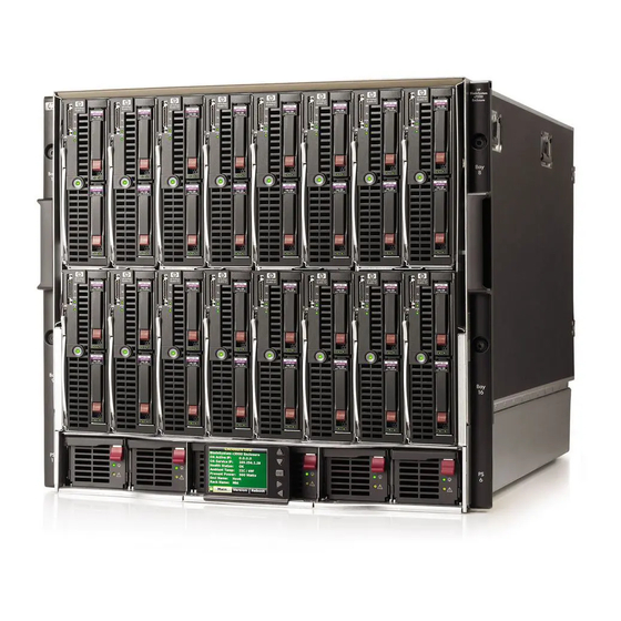
Component identification HP BladeSystem c7000 Enclosure components Enclosure front components Item Description Device bays* Air intake slot (Do not block.) Power supply bay 1 Power supply bay 2 Power supply bay 3 Power supply bay 4 Insight Display Power supply bay 5 Power supply bay 6 Air intake slot (Do not block.) -
Page 74: Device Bay Numbering
Device bay numbering Each enclosure requires interconnects to provide network access for data transfer. Interconnects reside in bays located on the rear of the enclosure. Be sure to review device bay numbering to determine which external network connections on the interconnects are active. IMPORTANT: When looking at the rear of the enclosure, front device bay numbering is reversed. -
Page 75: Power Supply Leds
Power supply LEDs Power LED 1 Fault LED 2 Condition (green) (amber) No AC power to the power supply Normal Power supply failure Power supply bay numbering Component identification 75... -
Page 76: Hp Bladesystem Insight Display
Insight Display overview The Insight Display enables the rack technician to configure the enclosure initially. It also provides information about the health and operation of the enclosure. See the HP BladeSystem Onboard Administrator User Guide for additional information. The Insight Display background color varies with the condition of the enclosure health: •... - Page 77 Accessing the Insight Display on the HP BladeSystem c7000 Enclosure The Insight Display is located on the front of the HP BladeSystem c7000 Enclosure. The Insight Display slides from side to side to allow access to enclosure components. HP BladeSystem Insight Display components...
-
Page 78: Enclosure Rear Components
Enclosure rear components Item Description Fan bay 1 Fan bay 2 Fan bay 3 Fan bay 4 Fan bay 5 Interconnect bay 2 Interconnect bay 4 Interconnect bay 6 Interconnect bay 8 Onboard Administrator bay 2 OA tray Power supply exhaust vent (do not block) Fan bay 10 Fan bay 9 Fan bay 8... - Page 79 7, 8 and then 5, 6 Mezzanine 3 For information on the location of LEDs and ports on individual interconnect modules, see the documentation that ships with the interconnect module. For more information, see the enclosure documentation on the HP website (http://www.hp.com/support). Component identification 79...
-
Page 80: Onboard Administrator Components
Onboard Administrator components Item Description Onboard Administrator bay 1 Onboard Administrator bay 2 (redundant, if used) Enclosure link-up port Enclosure link-down port Onboard Administrator LEDs and buttons Item Description Onboard Administrator UID LED Enclosure UID LED and UID button Onboard Administrator active LED Component identification 80... -
Page 81: Fan Bay Numbering
Item Description Onboard Administrator health LED Onboard Administrator reset button Fan bay numbering Fan LED LED color Fan status The fan is working. Solid green The fan has failed. Solid amber See the Insight Display screen. Flashing amber Component identification 81... -
Page 82: Hp Bladesystem C3000 Enclosure Components
HP BladeSystem c3000 Enclosure components Enclosure front components Item Description Device bays CD/DVD-ROM drive blank or CD/DVD-ROM drive (optional) Onboard Administrator tray (reserved for future use) Insight Display Onboard Administrator tray containing Onboard Administrator 1. Device bay numbering Each enclosure requires interconnects to provide network access for data transfer. Interconnects reside in bays located on the rear of the enclosure. - Page 83 Full-height device bay numbering Half-height device bay numbering Component identification 83...
- Page 84 HP BladeSystem Insight Display components Item Description Function Insight Display screen Displays Main Menu error messages and instructions Left arrow button Moves the menu or navigation bar selection left one position Right arrow button Moves the menu or navigation bar selection right one position...
- Page 85 Enclosure link-up port Enclosure link-down port Accessing the Insight Display on the HP BladeSystem c3000 Enclosure To access the Insight Display, push on the exposed end. Pull the Insight Display out of the chassis to lock it into place, and then tilt it up.
-
Page 86: Enclosure Rear Components
Rotate the Insight Display 90 degrees to view the display. Enclosure rear components Item Description KVM module bay Interconnect bay 1 Fan bays ("Fan bay numbering" on page 87) Interconnect bay 2 Enclosure link-down port Enclosure link-up port Onboard Administrator 1/iLO port Onboard Administrator 2/iLO port (reserved for future use) Component identification 86... - Page 87 Item Description Power supply bays ("Power supply bay numbering" on page 88) Interconnect bay 4 Interconnect bay 3 Fan bay numbering Fan LEDs LED color Fan status The fan is working. Solid green The fan has failed. Solid amber See the Insight Display screen. Flashing amber Component identification 87...
-
Page 88: Power Supply Bay Numbering
Power supply bay numbering Power supply LED Power LED Status No AC power to power supply units AC is present. Standby output is on, output is disabled. Green AC is present. Standby output is on, power supply DC output is on and Green Power supply failure (includes overvoltage and overtemperature) Component identification 88... - Page 89 Interconnect bay numbering To support network connections for specific signals, install the interconnect module in the appropriate bay. Server blade signal Interconnect bay Interconnect bay Notes number label — NICs 1, 2, 3, and 4 (embedded) Four port cards connect to bay 2 Mezzanine 1 Mezzanine 2 •...
-
Page 90: Software Tools And Solutions
Server blade diagnostic tools HP Insight Diagnostics HP Insight Diagnostics is a proactive server blade management tool, available in both offline and online versions, that provides diagnostics and troubleshooting capabilities to assist IT administrators who verify server blade installations, troubleshoot problems, and perform repair validation. -
Page 91: Array Diagnostic Utility
For more information, see the Management CD in the HP ProLiant Essentials Foundation Pack. Array Diagnostic Utility The HP Array Diagnostics Utility is a web-based application that creates a report of all HP storage controllers and disk drives. This report provides vital information to assist in identifying faults or conditions that may require attention. -
Page 92: Management Tools
You must install and use HP SIM to benefit from the Pre-Failure Warranty for processors, SAS and SATA hard drives, and memory modules. For additional information, refer to the Management CD in the HP ProLiant Essentials Foundation Pack or the HP SIM website (http://www.hp.com/go/hpsim). -
Page 93: Verifying Firmware Versions
Storage controllers Hard drives NICs • Verify the HP BladeSystem firmware by using the HP Systems Insight Manager (on page 92). • Verify the System Management Homepage on the Server Blade at the Software Information section • Verify the HP BladeSystem firmware by using the iLO 2 System Status Tab. -
Page 94: System Maintenance Tools
The VCA can be configured to point to a repository being managed by the VCRM, enabling easy version comparison and software updates. For more information about version control tools, refer to the HP Systems Insight Manager Help Guide and the Version Control User Guide on the HP Systems Insight Manager website (http://www.hp.com/go/hpsim). -
Page 95: Operating System Version Support
ROM upgrades required by each target server For more information, see the HP Smart Update Manager User Guide. The guide and the HP Smart Update Manager utility are available from the ProLiant Firmware Maintenance CD. This CD and others can be downloaded free of charge from the SmartStart download page on the HP website (http://www.hp.com/go/support). -
Page 96: Rom Update Utility
(http://www.hp.com/go/subscriberschoice). Change control and proactive notification HP offers Change Control and Proactive Notification to notify customers 30 to 60 days in advance of upcoming hardware and software changes on HP commercial products. For more information, refer to the HP website (http://www.hp.com/go/pcn). -
Page 97: Contacting Hp
HP's customer self-repair program offers you the fastest service under either warranty or contract. It enables HP to ship replacement parts directly to you so that you can replace them. Using this program, you can replace parts at your own convenience. -
Page 98: Operating System Information You Need
Number of processors and speed Number of DIMMs and their size and speed List of controllers and NICs List of connected peripheral devices List of any other optional HP or Compaq hardware Network configuration • Specific software information: Operating system information ("Operating system information you... -
Page 99: Linux Operating Systems
• A detailed description of the problem and any associated error messages Some of the previously listed logs might be available in the HPSreports (http://update.external.hp.com/HPS/HPSreports) that HP supports used to collect Windows® operating system logs. Linux operating systems Collect the following information: •... -
Page 100: Novell Netware Operating Systems
A list of each third-party software component installed, with the versions • A detailed description of the problem and any associated error messages Some of the previously listed tooling might be available in the tool called CFG2HTML as used by HP Support (ftp://iss:tools4AL@ftp.usa.hp.com). Novell NetWare operating systems Collect the following information: •... -
Page 101: Sun Solaris Operating Systems
• Which software group selected for installation: End User Support, Entire Distribution, Developer System Support, or Core System Support • If HP drivers are installed with a DU: DU number List of drivers in the DU diskette • The drive subsystem and file system information:... -
Page 102: Acronyms And Abbreviations
Command Line Interface DHCP Dynamic Host Configuration Protocol domain name system driver update EBIPA Enclosure Bay IP Addressing field replaceable unit HP SIM HP Systems Insight Manager input/output Integrated Lights-Out iLO 2 Integrated Lights-Out 2 Integrated Management Log Acronyms and abbreviations 102... - Page 103 Internet Protocol interrupt request LDAP Lightweight Directory Access Protocol Media Access Control network interface card NVRAM non-volatile memory Onboard Administrator power distribution unit product ID POST Power-On Self Test ProLiant Support Pack SNMP Simple Network Management Protocol Secure Shell unit identification Acronyms and abbreviations 103...
- Page 104 universal serial bus VCSU Virtual Connect Support Utility Acronyms and abbreviations 104...
-
Page 105: Index
73, 78, 82 errors, fan components, Onboard Administrator errors, Insight Display components, rear errors, installation configuration errors errors, location configuring the enclosure with HP BladeSystem Insight errors, power Display external KVM monitor connection problems Index 105... - Page 106 HP BladeSystem Insight Display, navigating 7, 77, LEDs 7, 73, 87, 88 LEDs, enclosure 73, 78 HP BladeSystem Insight Display, overview of LEDs, fan 81, 87 HP Insight Diagnostics LEDs, Onboard Administrator HP Insight Diagnostics survey functionality LEDs, power supply...
- Page 107 System Management Homepage Online ROM Flash Component Utility System Online ROM flash component utility operating systems 95, 98 system, keeping current overview, HP BladeSystem Insight Display Systems Insight Manager partner blade troubleshooting 41, 42 technical support partner blade troubleshooting, procedures...
- Page 108 troubleshooting, Onboard Administrator symptoms troubleshooting, partner blade symptoms troubleshooting, partner blades 41, 42 troubleshooting, power supply 30, 31 troubleshooting, remote troubleshooting, server blade 34, 37 troubleshooting, server blade symptoms UID LED 16, 80 updating the firmware upgrades compatibility matrix USB drive key using this guide utilities VCA (Version Control Agent)