Craftsman 921.16475 Owner's Manual
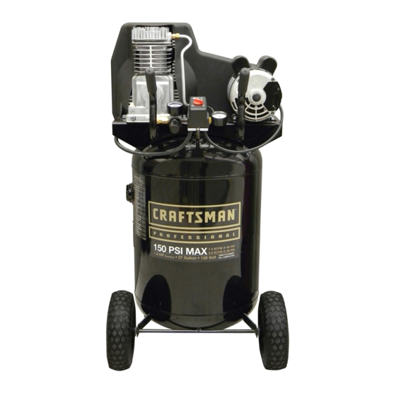
25/27 gallon oil lubricated, single stage, belt drive, electric
Hide thumbs
Also See for 921.16475:
- Owner's manual (41 pages) ,
- Owner's manual (18 pages) ,
- Owner's manual (17 pages)
Table of Contents
Advertisement
Available languages
Available languages
Owner's Manual
AIR COMPRESSOR
Oil Lubricated
Single Stage
Belt Drive, Electric
Model No. 921.16475 - 25 Gallon
Model No. 921.16474 - 27 Gallon
CAUTION:
Before using this product,
read this manual and follow
all its Safety Rules and
Operating Instructions.
Sears Brands Management Corporation, Hoffman Estates, IL 60179 U.S.A.
www.craftsman.com
5/6/2010
Part No. 200-2792
•
Safety Instructions
•
Installation & Operation
•
Maintenance & Storage
•
Troubleshooting Guide
•
Parts List
•
Español, p. 18
•
Français, p. 29
Advertisement
Chapters
Table of Contents

Related Manuals for Craftsman 921.16475


Summary of Contents for Craftsman 921.16475
-
Page 1: Air Compressor
Owner’s Manual AIR COMPRESSOR Oil Lubricated Single Stage Belt Drive, Electric Model No. 921.16475 - 25 Gallon Model No. 921.16474 - 27 Gallon CAUTION: • Safety Instructions Before using this product, • Installation & Operation read this manual and follow •... -
Page 2: Table Of Contents
Sears Brands Management Corporation, Hoffman Estates, IL 60179 U.S.A. SPECIFICATION CHART APPROXIMATE APPROXIMATE RUNNING TANK CAPACITY VOLTAGE/ CUT-IN CUT-OUT MODEL NO. H.P. GALLONS AMPS/PHASE PRESSURE PRESSURE 921.16474 Vert. 27 (102 liters) 115/15/1 (WLB1982713) (8,27 bar) (10,34 bar) 921.16475 Horiz. 25 (94,6 liters) 115/15/1 (WPB1982513) (8,27 bar) (10,34bar) 200-2792... -
Page 3: Safety Guidelines
SAFETY GUIDELINES The following information relates to protecting YOUR SAFETY and PREVENTING EQUIPMENT PROBLEMS. To help you recognize this information, we use the following symbols. Please read the manual and pay attention to these sections. DANGER: – A POTENTIAL HAZARD THAT WILL CAUSE SERIOUS INJURY OR LOSS OF LIFE. WARNING: –... -
Page 4: Glossary Of Terms
IMPORTANT SAFETY INSTRUCTIONS WARNING: RISK OF FIRE. Unattended operation of this compressor could result in personal injury or property damage. To reduce the risk of fire, do not allow the compressor to operate unattended. Always disconnect electrical power by turning the pressure switch to off and drain the tank daily or after each use. RISK TO BREATHING. -
Page 5: Overview
OVERVIEW BASIC AIR COMPRESSOR COMPONENTS The basic components of the air compressor are the electric motor, pump, pressure switch and tank (see Fig. 1). The electric motor (see A) powers the pump. The electric motor is equipped with an overload protector to help prevent possible motor burnout. -
Page 6: Compressor Controls
COMPRESSOR CONTROLS Pressure Switch (see A) Regulated Pressure Gauge (see F) This switch turns on the compressor. It is operated manually, This gauge measures the regulated line pressure. but when in the AUTO position, it allows the compressor to start up or shut down automatically, without warning, upon air demand. -
Page 7: Electrical Power Requirements
ELECTRICAL POWER REQUIREMENTS are not completely understood, or if in doubt as to whether the ELECTRICAL WIRING product is properly grounded. Do not modify the plug provided; if it will not fit the outlet, have the proper outlet installed by a Refer to the air compressor’s serial label for the unit’s voltage licensed electrician. -
Page 8: Operating Instructions
OPERATING INSTRUCTIONS Open the petcock (see E) to allow moisture to drain from BREAK-IN OF THE PUMP the tank. 1. Turn the pressure switch to the AUTO position (see C). Check the oil level in the pump (see “Checking the Oil” in the CAUTION: Escaping air and moisture can maintenance section). -
Page 9: Maintenance
MAINTENANCE compressor, and when the compressor is not in use. MAINTENANCE Do not use the unit with the shrouds or belt guard WARNING: removed. Serious injury could occur from contact To avoid personal injury, always shut off with moving parts. and unplug the compressor and relieve all air pressure from the system before performing any service on the air Proper belt tension and pulley alignment must be maintained... - Page 10 MAINTENANCE Shift the motor towards the pump to the point where the belt PULLEY ALIGNMENT can be easily removed and installed. NOTE: Once the motor pulley has been moved from its factory Remove and replace belt. NOTE: The belt must be centered set location, the grooves of the flywheel and pulley must over the grooves on the flywheel and motor pulley.
-
Page 11: Service Interval
MAINTENANCE Replace the transfer tube and tighten compression nuts. from the tank. Clean the filter element and filter housing; replace 10. Perform the “Break-in of the pump” procedure in the the element if necessary. Drain the oil from the pump crankcase Operating Instructions to make sure there are no leaks and and replace it with new oil. -
Page 12: Troubleshooting Chart
TROUBLESHOOTING Note: Troubleshooting problems may have similar causes and solutions. PROBLEM POSSIBLE CAUSE SOLUTION Excessive current draw Low voltage/motor overload Check that power supply is adequate and that compressor is on a trips circuit breaker or dedicated circuit. If using extension cord, try using without. If motor reset switch compressor is connected to a circuit protected by a fuse, use dual element time delay fuses (Buss Fusetron type “T”... -
Page 13: Parts Drawings And Parts Lists
PARTS DRAWING / ESQUEMA DE LAS PIEZAS / DESSIN DES PIÈCES Horizontal tank (25 Gal) Depósito horizontal Réservoir horizontal Vertical tank (27 Gal) Depósito vertical Réservoir vertical PARTS LIST / LISTA DE LAS PIEZAS / LISTE DE PIÈCES Item Part No. Artículo N.º... - Page 14 PARTS DRAWING / ESQUEMA DE LAS PIEZAS / DESSIN DES PIÈCES 200-2792...
- Page 15 PARTS LIST / LISTA DE LAS PIEZAS / LISTE DE PIÈCES Item Part No. Artículo Núm / P Cant Article No / P Qté Description Descripción Description 125-0151 Belt guard, outer Protector Garant Screw, #10-14 Tornillo 146-0016 Chaveta Clé 006-0009 Pulley Polea Poulie...
- Page 16 PARTS DRAWING / ESQUEMA DE LAS PIEZAS / DESSIN DES PIÈCES 130 Pump Assy Pump Specifications Weight–39 lbs. Oil Capacity (approx.)–18 oz. Sequence #’s 1, 2, 3, 4, 5, 6, 7 Min. RPM–700 & 8 Max, RPM–1200 Torque to 220–300 lbs-in Max.
- Page 17 PARTS LIST / LISTA DE LAS PIEZAS / LISTE DE PIÈCES 130 Pump Assy Item Part No. Description Descripción Description Artículo Núm / P Cant Article No / P Qté 059-0144 Screw, 5/16–18 x 2.50” lg Tornillo 054-0112 Ring set Juego de anillos Jeu d’anneaux 048-0065...
-
Page 18: Garantía
CUADRO DE ESPECIFICACIONES RUNNING PRESIÓN DE PRESIÓN DE H.P. CAPACIDAD DEL VOLTAJE ENCENDIDO APAGADO MODELO (CV) DEPÓSITO - LITROS AMP/FASE (APROXIMADA) (APROXIMADA) 921.16474 Vert. 102 Litros 115/15/1 (WLB1982713) (8,27 bar) (10,34 bar) 921.16475 Horiz. 94,6 litros 115/15/1 (WPB1982513) (8,27 bar) (10,34bar) 200-2792... -
Page 19: Pautas De Seguridad
PAUTAS DE SEGURIDAD La información que sigue se refiere a la protección de SU SEGURIDAD y la PREVENCIÓN DE PROBLEMAS DEL EQUIPO. Como ayuda para reconocer esta información, usamos los siguientes símbolos. Lea por favor el manual y preste atención a estas secciones. PELIGRO: - UN RIESGO POTENCIAL QUE CAUSARÁ... -
Page 20: Glosario De Términos
INSTRUCCIONES DE SEGURIDAD IMPORTANTES ADVERTENCIA: RIESGO DE •Nunca intente, por ningún motivo, ajustar la válvula de seguridad del depósito. Hacerlo anulará la garantía. La EXPLOSIÓN. válvula de seguridad ha sido preconfigurada en fábrica a la presión máxima que soporta esta unidad. Si se manipula la válvula de seguridad, existe el riesgo de que se produzcan lesiones personales o daños materiales. -
Page 21: Resumen General
RESUMEN GENERAL COMPONENTES BÁSICOS DEL COMPRESOR DE AIRE Los componentes básicos del compresor de aire son el motor eléctrico, la bomba, el interruptor de presión y el depósito (Fig. 1). El motor eléctrico (vea A) acciona la bomba. El motor eléctrico está... -
Page 22: Controles Del Compresor
CONTROLES DEL COMPRESOR Interruptor de presión (vea A) Gire el mando a la derecha para aumentar la presión, y a la Este interruptor enciende el compresor. Se opera izquierda para disminuirla. manualmente, pero cuando está en la posición ON, permite que Manómetro regulado (vea F) el compresor arranque o se pare automáticamente, sin aviso, Este manómetro mide presión de línea regulada. -
Page 23: Requisitos De Alimentación Eléctrica
REQUISITOS DE ALIMENTACION ELECTRICA Este producto está diseñado para utilizarse en un circuito de CABLEADO ELÉCTRICO 115 V (o en un circuito de 230 V si un electricista capacitado lo Consulte el rótulo del número de serie del compresor de aire modifica). -
Page 24: Instrucciones Operativas
INSTRUCCIONES OPERATIVAS de funcionamiento de la herramienta o del accesorio que PUESTA EN MARCHA INICIAL DE LA BOMBA esté usando. Coloque el conmutador de presión en la posición AUTO (vea PARADA Compruebe el nivel de aceite de la bomba (ver "Verificación Coloque el conmutador de presión presión en la posición del nivel de aceite"... -
Page 25: Mantenimiento
MANTENIMIENTO operaciones de mantenimiento en e compresor y cuando MANTENIMIENTO el compresor no esté en uso. No utilice la unidad sin las cubiertas o sin el protector de la correa, ya que podría ADVERTENCIA: Para evitar lesiones personales, sufrir lesiones por contacto con las piezas móviles. apague y desenchufe siempre el compresor y alivie toda la presión de aire del sistema antes de realizar cualquier Debe mantenerse la tensión correcta de la correa y la... - Page 26 MANTENIMIENTO CAMBIO DE LA CORREA DE TRANSMISIÓN RIESGO DE LESIONES. Esta unidad arranca RIESGO DE LESIONES. automáticamente. SIEMPRE apague el compresor, Esta unidad arranca quite el enchufe de la toma de corriente, y purgue automáticamente. SIEMPRE apague el compresor, toda la presión del sistema antes de realizar quite el enchufe de la toma de corriente, y purgue operaciones de mantenimiento en el al compresor y toda la presión del sistema antes de realizar...
-
Page 27: Intervalos De Servicio
MANTENIMIENTO depósito (sentido contrario a las agujas del reloj) utilizando REVISIÓN DE LA VÁLVULA DE ALIVIO una llave abierta de 7/8 pulg. Tire de la válvula de seguridad del depósito todos los días Con un lápiz o destornillador, empuje para asegurarse de que la válvula funciona adecuadamente, y con cuidado el disco de la válvula hacia para limpiar la válvula de cualquier obstrucción que pueda tener. -
Page 28: Cuadro De Detección De Fallos
CUADRO DE DETECCIÓN DE FALLOS Nota: Los problemas de detección de fallos pueden tener causas y soluciones similares. PROBLEMA CAUSA POSIBLE SOLUCION Consumo excesivo Voltaje bajo/sobrecarga del motor Verifique que el suministro de energía sea el adecuado y que el de corriente que compresor se encuentre conectado en un circuito dedicado. -
Page 29: Garantie
TABLEAU DES SPÉCIFICATIONS PRESSION PRESSION RUNNING CAPACITÉ DU TENSION/ APPROXIMATIVE APPROXIMATIVE MODÉLE H.P. RÉSERVOIR - LITRES AMPS/PHASE DE CONJONCTION DE DISJONCTION 921.16474 Vert. 102 Litres 115/15/1 (WLB1982713) (8,27 bar) (10,34 bar) 921.16475 Horiz. 94,6 Litres 115/15/1 (WPB1982513) (8,27 bar) (10,34bar) 200-2792... -
Page 30: Consignes De Sécurité
CONSIGNES DE SÉCURITÉ Les informations suivantes concernent VOTRE SÉCURITÉ et LA PROTECTION DU MATÉRIEL CONTRE LES PANNES. Pour vous aider à identifier la nature de ces informations, nous utilisons les symboles suivants. Veuillez lire le manuel et prêter attention à ces sections. -
Page 31: Glossaire Des Termes
DIRECTIVES DE SÉCURITÉ IMPORTANTES AVERTISSEMENT: RISQUE • Ne pas ajuster la soupape de sûreté du réservoir sous aucun prétexte. Ajuster la soupape de sûreté annule D’ÉCLATEMENT. toutes les garanties. La soupape de sûreté a été réglée en usine selon la pression limite de cet appareil. Des blessures corporelles et/ou des dommages à... -
Page 32: Vue D'ensemble
VUE D’ENSEMBLE ÉLÉMENTS DE BASE DU COMPRESSEUR D’AIR Les éléments de base du compresseur d'air sont le moteur électrique, la pompe, le manostat et le réservoir. Le moteur électrique (A) actionne la pompe. Il est équipé d'un protecteur de surcharge pour ne pas griller. Le protecteur de surcharge arrête le moteur dès qu'il surchauffe. -
Page 33: Commandes Du Compresseur
COMMANDES DU COMPRESSEUR Manostat (A) pour augmenter la pression et dans le sens inverse pour la Cet interrupteur met en marche le compresseur. Il est réduire. actionné manuellement, mais, s'il se trouve sur la position ON, le Manomètre de pression régulée (F) compresseur se met en marche ou s'arrête automatiquement, Ce manomètre mesure la pression de sortie régulée. -
Page 34: Spécifications De L'alimentation
SPÉCIFICATIONS DE L'ALIMENTATION ÉLECTRIQUE plates de la fiche. Le fil de terre est recouvert d'une CÂBLAGE ÉLECTIQUE gaine d'isolement verte avec ou sans rayures jaunes. Pour vous renseigner sur les normes d'intensité et de tension Ce produit est conçu pour être utilisé sur un circuit de 115 volts de l'appareil, référez-vous à... -
Page 35: Mode D'emploi
MODE D’EMPLOI RODAGE DE LA POMPE ARRÊT Placer le manocontacteur en position OFF (C). Placer le manocontacteur en position OFF (C). Débranchez le cordon d'alimentation. Vérifier le niveau d'huile de la pompe (voir " Vérifier Réduire la pression du réservoir au moyen du tuyau de l'huile "... -
Page 36: Entretien
ENTRETIEN ENTRETIEN AJUSTEMENT DE LA COURROIE D'ENTRAINEMENT REMARQUE : La tension de la courroie et l'alignement de AVERTISSEMENT: Pour éviter les risques de la poulie se font simultanément. Chaque procédure est décrite blessures, arrêtez et débranchez toujours le séparément par souci de clarté. compresseur et libérez toute la pression d'air dans le AVERTISSEMENT: circuit avant de procéder à... - Page 37 ENTRETIEN ALIGNEMENT DE LA POULIE REMPLACEMENT DE LA COURROIE D'ENTRAINEMENT REMARQUE : La tension de la courroie et l'alignement de WARNING: la poulie se font simultanément. Chaque procédure est décrite Cet appareil se met en séparément par souci de clarté. marche automatiquement.
-
Page 38: Entretien Périodique
ENTRETIEN Prendre note de l'orientation pour faciliter peinture, remplacez-le. Votre garantie sera annulée si l'appareil l'assemblage, dévisser le clapet de non- est directement exposé à des saletés et de la peinture. retour du réservoir (sens antihoraire) en VÉRIFICATION DE LA SOUPAPE DE DÉCHARGE utilisant une clé... -
Page 39: Dépannage
DÉPANNAGE Remarque : Les problémes de dépannage peuvent avoir des causes et des solutions similaires. PROBLÈME CAUSE POSSIBLE SOLUTION Le prélèvement excessif de Tension insuffisante/surcharge Vérifiez que l’alimentation est adéquate et que le compresseur est courant cause le du moteur branché...