
Related Manuals for Toshiba 52HMX94


Summary of Contents for Toshiba 52HMX94
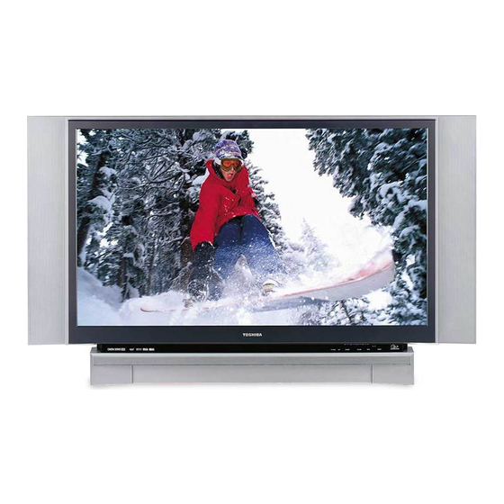
- Page 1 FILE NO. 020-200423 REVISION 2 SERVICE MANUAL Projection Television 52HMX94 62HMX94 Published in Japan, Jan. 2005 (YC) DOCUMENT CREATED IN JAPAN, Jan., 2005...
-
Page 2: Table Of Contents
TABLE OF CONTENTS CHAPTER 1 GENERAL ADJUSTMENTS SAFETY INSTRUCTIONS .............................. 3 SERVICE MODE ................................4 SPECIFIC INFORMATIONS CHAPTER 2 SETTING & ADJUSTING DATA ............................7 LAMP UNIT REPLACEMENT ............................8 LIGHT ENGINE REPLACEMANT..........................PARTS REPLACEMENT IN LIGHT ENGINE....................... EXPLODED VIEW ................................ 15 MECHANICAL DISASSEMBLY ............................ -
Page 3: Chapter 1 General Adjustments
CHAPTER 1 GENERAL ADJUSTMENTS SAFETY INSTRUCTIONS SAFETY PRECAUTION WARNING: Service should not be attempted by anyone unfamiliar with the necessary precautions on this receiver. The following are the necessary precautions to be observed before servicing this chassis. 1. An isolation transformer should be connected in the power line between the receiver and the AC line before any service is performed on the receiver. -
Page 4: Service Mode
SERVICE MODE 1. ENTERING SERVICE MODE 1) Press MUTE button twice 2) Press MUTE button 3) While pressing the MUTE button, on Remote Control. again and keep pressing. press MENU button on TV set. MUTE (Service mode display) 2. DISPLAYING THE ADJUSTMENT MENU 1) Press MENU button on TV. - Page 5 6. SELF DIAGNOSTIC FUNCTION 1) Press “9” button on Remote Control during display of adjustment menu in the service mode. The diagnosis will begin to check if interface among IC’s is executed properly. 2) During diagnosis, the following displays are shown. SELF CHECK NO.
- Page 6 7. LED indications The green and red LED lights on the TV control touchpad Control touchpad on TV front (on the lower right corner of the TV screen) indicate the TV's current status, as follows: Green ON = Control touchpad being pressed. TV/VIDEO EXIT CHANNEL...
-
Page 7: Chapter 2 Specific Informations
CHAPTER 2 SPECIFIC INFORMATIONS SETTING & ADJUSTING DATA SERVICE MODE ADJUSTING ITEMS AND DATA IN THE SERVICE MODE: Item Name of adjustment Preset Data RCUT R CUT OFF GCUT G CUTOFF BCUT B CUT OFF GDRV G DRIVE BDRV B DRIVE BRTC BRIGHT CENTER SCNT... -
Page 8: Lamp Unit Replacement
LAMP UNIT REPLACEMENT Cautions when replacing LAMP UNIT (SK02) The light source for this TV is a mercury lamp with internal atmospheric pressure that increases during use. The lamp has a limited service life that varies depending on user settings. If you use the lamp beyond its service life: you may notice a reduction in the colors and/or brightness of the pic- ture;... - Page 9 Turn off the TV and unplug the power cord. Grasp the lamp unit handle and gently pull the lamp unit straight out of the TV. Set the old lamp unit aside. STOP! Allow the lamp to cool for at least one (1) hour before replacing it.
- Page 10 Reattach the lamp unit door, making sure to insert the hook on the left side of the lamp unit door inside the opening in the TV cabinet. Replace the thumb screw and hand-tighten. Plug in the power cord and turn on the TV. After the initial warmup period (which may take up to 45 seconds for full picture brightness), the TV should operate nor- mally.
-
Page 11: Light Engine Replacemant
LIGHT ENGINE REPLACEMENT Cautions when replacing LIGHT ENGINE 1-2. Adjustment is made from service mode. The adjusting items consist of CWDL, CWDH and DMDB. LIGHT ENGINE UNIT: A271: PJ-TB25-52/62 (Including with SK02 to SK08) CWDL CWDH SK01: PJ-TB-25-52S/62S (Including with SK03 to SK08 except SK02) When CW delay number of the data bar code is 0450: LIGHT ENGINE is a heart of the TV and emits high heat. - Page 12 Conversion Table for Decimal and Hexadecimal Numbers CW delay CW delay CW delay CW delay CW delay CWDH CWDL CWDH CWDL CWDH CWDL CWDH CWDL CWDH CWDL number number number number number 0000 0370 0740 1110 1480 0005 0375 0745 1115 1485 0010...
-
Page 13: Parts Replacement In Light Engine
PARTS REPLACEMENT IN LIGHT ENGINE 2-3. Detach the ballast power unit by removing 4 substrate FAN Replacement (SK06 and SK07) stoppers that hold the ballast power unit. 1-1. For replacing FAN for cooling heatsink (SK07), remove 2 screws. For replacing FAN for cooling lamp (SK06), detach CAUTION FAN hood located on LIGHT ENGINE by removing 2 Precautions When Exchanging Ballast Power Units... - Page 14 23125919 FAN, D07F-12SS18 01B(EX) SK08 23144199 BREAKER, US-603UXTLQE-H US-603UXTLQE-H 4-3. Remove 2 screws holding Photo Detector substrate #1:[52HMX94] #2:[62HMX94] (SK04). Color wheel Photo Detector substrate (SK04) Caution When removing screws, do not damage the color wheel with drivers, etc. Even a small im- pact may damage the color wheel.
-
Page 15: Exploded View
EXPLODED VIEW W661 12 screws 4 screws Note ; A205 (Back Cover Assy) includes A204, W661 and W662 except A101. A204 K601 12 screws M4 ✕ 16 M4 ✕ 16 4 screws M4 ✕ 16 3 screws 3 screws A101 E045Z 2 screws W662... -
Page 16: Mechanical Disassembly
MECHANICAL DISASSEMBLY 1. Rear Cover Removal 2. Touchpad & Bezel Ass'y Removal 12 screws A201 A401 E045Z 2 screws 2 screws 4 screws 2 screws UV03 UC01 UA06 A227 1 screw 13 screws A333 A222 3. Mirror Removal 4. Speaker Removal A205 A204 4 screws... -
Page 17: Chassis Replacement Parts List
• The part number must be used when ordering parts, in order to assist in processing, be sure to include the Model number and Description. ∗ • The PC board assembly with mark is no longer available after the end of the production. Model : 52HMX94/62HMX94 Capacitors ..... CD Ceramic Disk : Plastic Film : Electrolytic Resistors .... - Page 18 Location Location Parts No. Description Parts No. Description C8240 24073038 ELECTROLYTIC, 16V 100UF M 3A CC17 24619100 ELECTROLYTIC, 16V 10UF M C8241 24503047 PLASTIC FILM, 63V 0.33UF J CC18 24092730 CERAMIC CHIP, 16V B 0.1UF K C8242 24073141 ELECTROLYTIC CE04P 10V 1000UF M 3A CC19 24092730 CERAMIC CHIP, 16V B 0.1UF K C8250...
- Page 19 Location Location Parts No. Description Parts No. Description CE86 24073133 ELECTROLYTIC CE04P 6.3V 3300UF M 3A CV73 24092730 CERAMIC CHIP, 16V B 0.1UF K CE87 24073141 ELECTROLYTIC CE04P 10V 1000UF M 3A CV74 24092730 CERAMIC CHIP, 16V B 0.1UF K CE88 24073155 ELECTROLYTIC, 16V 1000UF M 3A CV75...
- Page 20 Location Location Parts No. Description Parts No. Description R662 24011333 CHIP, 1/20W 33K OHM J R8904 24366472 CARBON FILM, 1/6W 4.7K OHM J R663 24011822 CHIP, 1/20W 8.2K OHM J R8905 24366681 CARBON FILM, 1/6W 680 OHM J R665 24011223 CHIP, 1/20W 22K OHM J R8908 24366104 CARBON FILM, 1/6W 100K OHM J R666...
- Page 21 Location Location Parts No. Description Parts No. Description RB504 24366104 CARBON FILM, 1/6W 100K OHM J RE45 24000356 METAL FILM, 1/4W 820 OHM F RB505 24366101 CARBON FILM, 1/6W 100 OHM J RE46 24000529 METAL FILM, 1/4W 6.8K OHM F RB506 24366390 CARBON FILM, 1/6W 39 OHM J RE48...
- Page 22 Location Location Parts No. Description Parts No. Description RV073 24011102 CHIP, 1/20W 1K OHM J L892 23248292 COIL, CHOKE, TLN3499GH RV08 24011101 CHIP, 1/20W 100 OHM J L893 23248213 COIL, CHOKE, TLN3481AH RV09 24011101 CHIP, 1/20W 100 OHM J L8930 23248292 COIL, CHOKE, TLN3499GH RV10 24011101 CHIP, 1/20W 100 OHM J...
- Page 23 Location Location Parts No. Description Parts No. Description Q847 23314965 TRANSISTOR, KTC3198 Y D602 23316231 DIODE, 1SS355 Q862 23000823 IC, PHOTO COUPLER, TLP421F(GR) D603 23316231 DIODE, 1SS355 Q881 23000701 IC, NJM431L D604 23316231 DIODE, 1SS355 Q8200 23085050 IC, SI-3120J(LF1101) D605 23316231 DIODE, 1SS355 Q8210 23000469 IC, PQ5EV3...
- Page 24 Location Location Parts No. Description Parts No. Description DE01 23316391 DIODE, D3SB60(4103) HX19A 23103327 CORE, FERRITE W33X6.5X12 TFE1023 DE10 23316672 DIODE, ZENER, MTZJ5.6B JR001 24000445 CHIP JUMPER, 1608TYPE DE12 23118859 DIODE, 1SS133 JR002 24000445 CHIP JUMPER, 1608TYPE DE13 23118859 DIODE, 1SS133 JR003 24000445 CHIP JUMPER, 1608TYPE DE14...
- Page 25 UC01 23762334 PC BOARD ASSY, MULTICARD 51H94 PU PD1821A 23405383 MIRROR, 62C4M3 1426/695*725*3 MIRROR62C4M3 UD02 #1 23148142 PC BOARD ASSY DIGITAL, 52HMX94 DSB-SHU153D 23148143 PC BOARD ASSY DIGITAL, 62HMX94 DSB-SHU153E UE01 23763977 PC BOARD ASSY, SUB POWER HM94 PU PD1820B...
-
Page 26: Pc Boards Top And Bottom View
BACK AV BOARD PD1939B (U103) BOTTOM (FOIL) SIDE PB507 PB60 PB503 PX18 PX19 CV73 RV70 RV70 RV76 RV90 RV76 10 9 DV01 RV74 RV38 R513 RV74 DV03 PJ61 RV93 Q519 RV009 QV71 DV05 R606 RV013 PJ60 R605 Q519 RV013 RV009 RV023 DV07 QB511... - Page 27 BACK AV BOARD PD1939B (U103) TOP (COMPONENT) SIDE PB60 PX18 QV01 PX19 CV01 PB503 PB507 CV01 PJ60 RV01 P900 RV03 CV03 CV03 P901 CB505 RV06 CV04 CV04 QB511 RV07 RV08 CV05 CV05 CV11 RV11 RB558 CV11 CV13 RV12 CV13 RV14 QB509 QB510 PJ63...
- Page 28 MAIN POWER BOARD PD1773B-1 (U802) BOTTOM (FOIL) SIDE P891 F8210 D883 R888 L890 1.5A 125V D866 R885 C883 R866 D865 C884 L861 B1-V-0 Q862 P892 R869 D883A L881 R887 Q881 C886 R886 Q8210 Q801A L892 D884 F881 DDcon 3.4V 500mA 125V C8215 D886 L882...
- Page 29 IF AUDIO AC IN BOARD PD1775C (U101) BOTTOM (FOIL) SIDE D614 P807B D894 R892 R693 D611 P106 D895 R152 BB20 BB10 D896 R155 D612 R155 R152 R154 D612 R612 Q612 D897 D101 T802 Q153 D615 R687 GJ151 R614 Q612 R614 CY102 R613 R611...
- Page 30 SUB POWER BOARD PD1820B (UE01) MULTI CARD BOARD PD1821A (UC01) IR BLASTER BOARD PD1289 (E045Z) BOTTOM (FOIL) SIDE BOTTOM (FOIL) SIDE BOTTOM (FOIL) SIDE CCP-3400 23547648 B1-V-0 DB51 RB51 DB51A LE54 RB63 LE60 LE57 DE76A DE76 CB60 CB52 CE86 RB60 DS-7405 CE50 CC02...
- Page 31 OPSS SCALER BOARD (52HMX94:SHU153D 62HMX94:SHU153E) (UD02) SEINE_PJTV (PD1941) BOTTOM (FOIL) SIDE L229 PJ901 D209 Q210 C2207 C1281 C202 C2203 Q209 C2206 PJ900 IC320 C353 C372 L306 L305 L310 L309 D307 IC221 L727 L726 L725 R323 C338 DP205 C381 L308 C749...
- Page 32 OPSS SCALER BOARD (52HMX94:SHU153D 62HMX94:SHU153E) (UD02) SEINE_PJTV (PD1941) TOP (COMPONENT) SIDE L229 PJ901 D209 Q210 C2207 C1281 C202 C2203 PJ900 PJ901 Q209 C1281 R208 R207 R206 R205 C2207 W213 W255 C2206 L229 PJ900 D209 W250 C243 R211 R318 IC221 C202...
- Page 33 OPSS SCALER BOARD (52HMX94:SHU153D 62HMX94:SHU153E) (UD02) DIGITAL (PD1940) TOP (COMPONENT) SIDE PJ13 IC603 PJ17 PJ11 L6009 PJ20 FL605 FL604 W3050 L3006 Q6007 L3007 C8003 C8009 C8008 FL603 Q6009 C6001 D8012 Q6012 Q6011 C6095 Q6010 R6145 C6011 R6010 IC506 RM310 IC505...
- Page 34 OPSS SCALER BOARD (52HMX94:SHU153D 62HMX94:SHU153E) (UD02) POD (PD1942) TOP (COMPONENT) SIDE RM629 RM630 RM627 RM628 L606 IC602 L614 IC603 L605 C602 L615 C601 L604 C603 R609 R613 C618 R605 R607 R606 DP606 C619 C617 DP608 R602 R604 DP607 R603 R608...
- Page 35 SCHEMATIC DIAGRAM MODEL : 52HMX94/62HMX94 WARNING : BEFORE SERVICING THIS CHASSIS, READ THE “SAFETY PRECAUTION” AND “PRODUCT SAFETY NOTICE” ON PAGE 3 OF THIS MANUAL. CAUTION: The international hazard symbols " " in the schematic diagram and the parts list designate components which have special characteristics important for safety and should be replaced only with types identical to those in the original circuit or specified in the parts list.
- Page 36 SCHEMATIC DIAGRAM STRUCTURE BACK_AV (1/6) [SHEET-1/6] ....1/125 (AUDIO_SELECT) [SHEET-2/6] ....2/125 (VIDEO_SELECT1) [SHEET-3/6] ....3/125 (VIDEO_SELECT2) [SHEET-4/6] ....4/125 (IR_BLASTER) [SHEET-5/6] ....5/125 (WRIGHT_CONNECTION) [SHEET-6/6] ....6/125 FAN_CONTROL ............................7/125 FRONT_AV ..............................8/125 FRONT_KEY (TOUCH_CONTROL_PANEL) ................9/125 IF_AUDIO (IF/AUDIO) [SHEET-1/4] ....
- Page 37 SEINE_PJTV (SEINE_CAPTURE_IN [SHEET-200] ....63/125 (CPLD-VIDEO_SW) [SHEET-202] ....64/125 (VIDEO_LPF_VBL) [SHEET-203] ....65/125 (VIDEO_LPF_VCD) [SHEET-204] ....66/125 (VIDEO_IN-NTSDECORDER1) [SHEET-205] ....67/125 (VIDEO_IN-NTSDECORDER2) [SHEET-206] ....68/125 (VIDEO_IN-MPEG_ENC1) [SHEET-208] ....69/125 (VIDEO_IN-MPEG_ENC2) [SHEET-209] ....70/125 (VIDEO_IN-MPEG_ENC3) [SHEET-210] ....71/125 (VIDEO_IN-MPEG_ENC4) [SHEET-211] ....72/125 (MPEG_AUDIO_PLL) [SHEET-212] ....
- Page 38 - 47 -...