Toshiba TOSVERT VF-FS1 Instruction Manual
Industrial inverter for 3-phase induction motors
Hide thumbs
Also See for TOSVERT VF-FS1:
- Instruction manual (252 pages) ,
- Function manual (38 pages) ,
- Instruction manual (72 pages)
Table of Contents
Advertisement
Quick Links
Industrial Inverter
For 3-phase induction motors
Instruction Manual
TOSVERT
3-phase 200V class 0.4
3-phase 400V class 0.4
1. Make sure that this instruction manual is delivered to the
end user of the inverter unit.
2. Read this manual before installing or operating the inverter
unit, and store it in a safe place for reference.
FS1
VF-
TM
30kW
75kW
NOTICE
E6581381
I
Safety
precautions
II II
Introduction
Contents
1
Read first
2
Connection
3
Operations
4
Basic VF-FS1
operations
5
Basic
parameters
6
Extended
parameters
7
Applied
operation
8
Monitoring the
operation status
9
Measures
to satisfy the
standards
10 10
Peripheral
devices
11 11
Table of
parameters
and data
12 12
Specifications
13 13
Before making
a service call
14 14
Inspection and
maintenance
15 15
Warranty
16 16
Disposal of the
inverter
2009 Ver. 118/119
Advertisement
Table of Contents

Related Manuals for Toshiba TOSVERT VF-FS1


Summary of Contents for Toshiba TOSVERT VF-FS1
-
Page 1: Industrial Inverter
E6581381 Safety precautions II II Introduction Contents Industrial Inverter Read first For 3-phase induction motors Connection Operations Instruction Manual Basic VF-FS1 operations Basic parameters TOSVERT Extended parameters Applied operation Monitoring the operation status Measures to satisfy the standards 10 10 3-phase 200V class 0.4 30kW Peripheral... -
Page 2: Safety Precautions
E6581381 Safety precautions The items described in these instructions and on the inverter itself are very important so that you can use the inverter safely, prevent injury to yourself and other people around you as well as to prevent damage to property in the area. -
Page 3: General Operation
E6581381 General Operation Warning See item • Never disassemble, modify or repair. This can result in electric shock, fire and injury. For repairs, call your sales distributor. Disassembly prohibited • Never remove the front cover when power is on or open door if enclosed in a cabinet. The unit contains many high voltage parts and contact with them will result in electric shock. - Page 4 Operation cannot be stopped immediately by the inverter alone, thus risking an accident or injury. • All options used must be those specified by Toshiba. 1.4.4 The use of any other option may result in an accident.
- Page 5 E6581381 Warning See item • Electrical installation work must be done by a qualified expert. Connection of input power by someone who does not have that expert knowledge may result in fire or electric shock. • Connect output terminals (motor side) correctly. If the phase sequence is incorrect, the motor will operate in reverse and that may result in injury.
-
Page 6: Maintenance And Inspection
E6581381 Caution See item • Observe all permissible operating ranges of motors and mechanical equipment. (Refer to the motor's instruction manual.) Not observing these ranges may result in injury. Prohibited When sequence for restart after a momentary failure is selected (inverter) Caution See item •... - Page 7 E6581381 Disposal Caution See item • If you throw away the inverter, have it done by a specialist in industry waste disposal(*). If you throw away the inverter by yourself, this can result in explosion of capacitor or produce noxious gases, resulting in injury. (*) Persons who specialize in the processing of waste and known as "industrial waste product collectors and transporters"...
-
Page 8: Industrial Inverter
3. Superior basic performance Automatic energy-saving Smooth operation : Reduced rotation ripple through the use of Toshiba's unique waveform formation. Built-in current surge suppression circuit : Can be safely connected even if power load is low. Maximum 200Hz high frequency output : Optimum for use with high speed motors such as those in lumber machinery and milling machines. -
Page 9: Table Of Contents
E6581381 Contents Safety precautions .................................1 Introduction ..................................7 1. Read first..................................A-1 Check product purchase ............................A-1 Contents of the product............................A-2 Names and functions ............................A-3 Notes on the application ............................A-13 2. Connection..................................B-1 Cautions on wiring .............................B-1 Standard connections ............................B-2 Description of terminals .............................B-5 3. - Page 10 E6581381 Terminal function selection ..........................F-6 Basic parameters 2............................F-15 Frequency priority selection ..........................F-16 Operation frequency............................F-24 DC braking................................. F-25 Auto-stop in case of lower-limit frequency continuous operation ..............F-26 Jump frequency-jumping resonant frequencies....................F-28 6.10 Bumpless operation............................F-29 6.11 PWM carrier frequency............................
- Page 11 E6581381 12. Specifications................................L-1 12.1 Models and their standard specifications......................L-1 12.2 Outside dimensions and mass ...........................L-4 13. Before making a service call - Trip information and remedies ..................M-1 13.1 Trip causes/warnings and remedies ........................M-1 13.2 Restoring the inverter from a trip ........................M-5 13.3 If the motor does not run while no trip message is displayed ................M-6 13.4...
-
Page 12: Read First
E6581381 1. Read first Check product purchase Before using the product you have purchased, check to make sure that it is exactly what you ordered. Caution Use an inverter that conforms to the specifications of power supply and three-phase induction motor being used. -
Page 13: Contents Of The Product
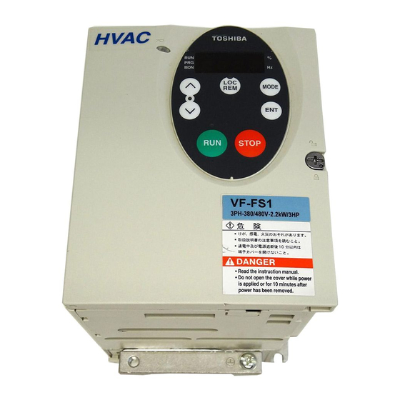
E6581381 Contents of the product Explanation of the name plate label. Type Form V F F S 1 - 4 0 0 7 P L E - W N - A 2 2 Applicable motor Default interface Special specification code Model name Input (AC) voltage Additional functions I... -
Page 14: Names And Functions
E6581381 Names and functions 1.3.1 Outside view [Operation panel]... - Page 15 E6581381 Unlock position mark The front panel is unlocked when the dot on the locking screw is on Charge lamp this (upper) side. Indicates that high voltage is still present within the inverter. Do not Front panel locking screw open the terminal board cover The inverter came with this while this is lit.
- Page 16 E6581381 ・Monitor display The LEDs on the operation panel display the following symbols indicate operations and parameters. LED(number) LED(alphabet) Example of the label 1.3.2 Power circuit and control circuit terminal boards In case of the lug connector, cover the lug connector with insulated tube, or use the insulated lug connector. 1) Power circuit terminal board In case of the lug connector, cover the lug connector with insulated tube, or use the insulated lug connector.
- Page 17 E6581381 VFFS1-2004 ∼ 2037PM VFFS1-4004 ∼ 4055PL Note: EMC plate is supplied as standard only WP model.
- Page 18 E6581381 VFFS1-2055, 2075PM -4075, 4110PL VFFS1-2110 ∼ 2185PM -4150 ∼ 4185PL Note: EMC plate is supplied as standard only WP model.
- Page 19 E6581381 VFFS1-2220PM -4220, 4300, 4370, 4450PL ( ⇒ See page A-10) Grounding capacitor disconnecting switch (4220, 4300PL only) ( ⇒ See page A-10) VFFS1-2300PM -4550, 4750PL Grounding capacitor disconnecting switch (400V only) ( ⇒ See page A-10) Each main circuit terminal has the structure shown in the figure below.
- Page 20 E6581381 2) Grounding capacitor disconnecting switch and taps Caution The grounding capacitor disconnecting tap is provided with a protection cover. To avoid shock hazards, always attach the cover after connecting or disconnecting the capacitor to or from the tap. Mandatory Every three-phase 400V model has a built-in high-attenuation noise filter, which is grounded through a capacitor.
- Page 21 E6581381 22kW or more: Switch To change the capacitance from Small to Large, push this switch. (Factory default position) To change the capacitance from Large to Small, pull up this switch. 3) Control circuit terminal board The control circuit terminal board is common to all equipment. M3 screw 0.5N•m 4.4 lb・in...
- Page 22 E6581381 1.3.3 How to open the front (terminal board) cover-18.5kW or less To wire the terminal board, remove the front lower cover in line with the steps given below. Turn the locking screw on the right side of the front panel 90° counterclockwise to align the dot on the screw with the unlock Pull the front panel toward you position mark (upper side).
- Page 23 E6581381 1.3.4 How to open the front (terminal board) cover-22kW or more To wire the main circuit terminal board for models 22kW or more, remomve the front cover. Remove the screw Maincircuit terminal board Control circuit terminal board Open the control circuit terminal board cover. * To open the cover, lift it with your finger placed at the part on the right side of the cover.
-
Page 24: Notes On The Application
E6581381 Notes on the application 1.4.1 Motors When the VF-FS1 and the motor are used in conjunction, pay attention to the following items. Caution Use an inverter that conforms to the specifications of power supply and three-phase induction motor being used. If the inverter being used does not conform to those specifications, not only will the three- phase induction motor not rotate correctly, but it may cause serious accidents through overheating and Mandatory fire. - Page 25 E6581381 Low loads and low inertia loads The motor may demonstrate instability such as abnormal vibrations or overcurrent trips at light loads of 5 % or under of the load percentage, or when the load's inertia moment is extremely small. If that happens reduce the carrier frequency.
- Page 26 E6581381 Braking motor When using a braking motor, if the braking circuit is directly connected to the inverters's output terminals, the brake cannot be released because of the lowered starting voltage. Therefore, when using a braking motor, connect the braking circuit to the inverter's power supply side, as shown in the figure below.
- Page 27 E6581381 Power factor correction capacitor Power factor correction capacitors cannot be installed on the output side of the inverter. When a motor is run that has a power factor correction capacitor attached to it, remove the capacitors. This can cause inverter malfunction trips and capacitor destruction.
-
Page 28: What To Do About The Leak Current
E6581381 Disposal If an inverter is no longer usable, dispose of it as industrial waste. 1.4.3 What to do about the leak current Caution Current may leak through the inverter's input/output wires because of insufficient electrostatic capacity on the motor with bad effects on peripheral equipment. - Page 29 E6581381 (2) Affects of leakage current across lines Thermal relays Inverter Power supply Leakage current path across wires Thermal relays The high frequency component of current leaking into electrostatic capacity between inverter out- put wires will increase the effective current values and make externally connected thermal relays operate improperly.
-
Page 30: Instruction Manual
E6581381 CT and ammeter If a CT and ammeter are connected externally to detect inverter output current, the leak current's high frequency component may destroy the ammeter. If the wires are more than 50 meters long, it will be easy for the high frequency component to pass through the externally connected CT and be superimposed on and burn the ammeter with models having motors of low rated current (several A(ampere) or less), especially the 400V class low capacity (5.5kW or less) models, because the leak current will increase in proportion to the motor's rated current. - Page 31 If the VF-FS1 Inverter is installed in a location that is subject to vibration, anti-vibration measures are required. Please consult with Toshiba about these measures. • If the VF-FS1 Inverter is installed near any of the equipment listed below, provide measures to insure against errors in operation.
- Page 32 Operation cannot be stopped immediately by the inverter alone, thus risking an accident or injury. • All options used must be those specified by Toshiba. The use of any other option may result in an accident.
- Page 33 E6581381 Calorific values of the inverter and the required ventilation About 5% of the rated power of the inverter will be lost as a result of conversion from AC to DC or from DC to AC. In order to suppress the rise in temperature inside the cabinet when this loss becomes heat loss, the interior of the cabinet must be ventilated and cooled.
- Page 34 E6581381 • Separate the input (power) and output (motor) wires of the main circuit. Do not place them in the same conduit, do not run them parallel, and do not bundle them. • Ground the inverter ground terminals ( • Install surge suppressor on any magnetic contactor and relay coils used around the inverter. •...
-
Page 35: Connection
E6581381 2. Connection Warning • Never disassemble, modify or repair. This can result in electric shock, fire and injury. For repairs, call your sales agency. Disassembly prohibited • Don't stick your fingers into openings such as cable wiring hole and cooling fan covers. This can result in electric shock or other injury. -
Page 36: Standard Connections
E6581381 Warning • Ground must be connected securely. If the ground is not securely connected, it could lead to electric shock or fire when a malfunction or current leak occurs. Be Grounded Caution • Do not attach devices with built-in capacitors (such as noise filters or surge absorber) to the output (motor side) terminal. - Page 37 E6581381 2.2.1 Standard connection diagram 1 This diagram shows a standard wiring of the main circuit.
- Page 38 E6581381 2.2.2 Standard connection diagram 2...
-
Page 39: Description Of Terminals
E6581381 Description of terminals 2.3.1 Power circuit terminals This diagram shows an example of wiring of the main circuit. Use options if necessary. Power supply and motor connections Connections with peripheral equipment Molded-case noise reduction Surge suppression circuit Magnetic Input AC filter filter breaker... -
Page 40: Control Circuit Terminals
E6581381 Power circuit Terminal symbol Terminal function Grounding terminal for connecting inverter. There are 3 terminals in total. 2 terminals in (PE) the terminal board, 1 terminal in the cooling fin. 200V class: three-phase 200 to 240V-50/60Hz R/L1,S/L2,T/L3 400V class: three-phase 380 to 480V-50/60Hz Connect to a (three-phase induction) motor. - Page 41 E6581381 Terminal Electrical Input/output Function Inverter internal circuits symbol specifications 10Vdc Output Analog power supply output (permissible load current: 10mA) Multifunction programmable analog input. Factory default setting: 0~10Vdc/0~60Hz (0~50Hz) frequency input. The function can be changed to 10Vdc 4~20mAdc (0~20mA) current input by (internal impedance: flipping the VIA (SW3) dip switch to the I position.
- Page 42 E6581381 Terminal Electrical Input/output Function Inverter internal circuits symbol specifications Multifunction programmable relay contact 250Vac-1A output. (cosφ=1) Detects the operation of the inverter's : at resistance load Output protection function. 30Vdc-0.5A Contact across FLA-FLC is closed and FLB- 250Vac-0.5A FLC is opened during protection function (cosφ=0.4) operation.
- Page 43 E6581381 SINK (Negative) logic/SOURCE (Positive) logic (When an external power supply is used) The PLC terminal is used to connect to an external power supply or to insulate a terminal from other input or output terminals. As for input terminals, turn the SW4 slide switch to the PLC position. <Examples of connections when an external power supply is used>...
- Page 44 E6581381 The figure on the right shows an example of the connection of input terminals VIA when there is used as contact input terminals. This example illustrates the connection when the inverter is used in sink (Negative) logic mode. In case source (Positive) logic mode, connect the resistor between VIA and CC.
-
Page 45: Operations
E6581381 3. Operations Warning • Do not touch inverter terminals when electrical power is going to the inverter even if the motor is stopped. Touching the inverter terminals while power is connected to it may result in electric shock. Prohibited •... -
Page 46: Simplified Operation Of The Vf-Fs1
E6581381 Simplified Operation of the VF-FS1 The procedures for setting operation frequency and the methods of operation can be selected from the following. : (1) Run and stop from the operation panel Start / Stop (2) Run and stop using external signals to the terminal board (3) Run and stop through RS485 communication : (1) Setting using the operation panel... - Page 47 E6581381 3.1.1 How to start and stop Example of a setting procedure Key operated LED display Operation Displays the operation frequency (operation stopped). (When standard monitor display selection = [Operation frequency]) Displays the first basic parameter [Wizard function ()]. ...
- Page 48 E6581381 3.1.2 How to set the frequency Example of a setting procedure Key operated LED display Operation Displays the operation frequency (operation stopped). (When standard monitor display selection = [Operation frequency]) Displays the first basic parameter [Wizard function ()]. MODE ...
-
Page 49: Frequency Setting
E6581381 (2) Setting the frequency using the operation panel (= or ) Frequency setting Setting the frequency using external potentiometer Potentiometer Setting frequency using the potentiometer (1k-10kΩ, 1/4W) ⇒ For more detailed information on adjustments, see section 6.5. : Setting frequency using potentiometer 60Hz Frequency... -
Page 50: How To Operate The Vf-Fs1
E6581381 How to operate the VF-FS1 Overview of how to operate the inverter with simple examples. Remote mode selection, Ex.1 Setting the operation frequency using the operation panel and running and stopping using the operation panel. Wiring PA/+ PC/- Motor MCCB R/L1 U/T1... - Page 51 E6581381 Remote mode selection, Ex.2 Operation frequency setting, running and stopping using external signals. Wiring PA/+ PC/- Motor MCCB R/L1 U/T1 S/L2 V/T2 Noise Power circuit W/T3 T/L3 filter Run forward signal Control circuit Run backward signal Common Voltage signal: 0∼10V, Current signal: 4∼20mA External potentiometer (Otherwise, input voltage signal (0~10V) between the terminals VIA-CC.) Parameter setting...
-
Page 52: Basic Vf-Fs1 Operations
E6581381 4. Basic VF-FS1 operations The VF-FS1 has the following three monitor modes. : The standard inverter mode. This mode is enabled when Standard monitor mode inverter power goes on. This mode is for monitoring the output frequency and setting the frequency designated value. -
Page 53: Flow Of Status Monitor Mode
E6581381 Flow of status monitor mode Flow of monitor as following... -
Page 54: How To Set Parameters
E6581381 How to set parameters The standard default parameters are programmed before the unit is shipped from the factory. Parameters can be divided into 5 major categories. Select the parameter to be changed or to be searched and retrieved. : The basic parameters that must be programmed Basic parameters before the first use. - Page 55 E6581381 4.2.1 How to set the basic parameters All of the basic parameters can be set by the same step procedures. [Steps in key entry for basic parameters] * Parameters were factory-set by default Switches to the setting monitor mode. before shipment.
-
Page 56: How To Set Extended Parameters
E6581381 4.2.2 How to set extended parameters The VF-FS1 has extended parameters to allow you to make full use of its functions. All extended parameters are expressed with and three digits. Basic parameters ∼ MODE Press the key or the key to Press the MODE key once and use the change the set value. - Page 57 E6581381 Example of parameter setting Steps in setting are as follows (Example of Auto-restart control selection from 0 to 1.) Key operated LED display Operation Displays the operation frequency (operation stopped). (When standard monitor display selection = [Operation . frequency]) The first basic parameter “”...
- Page 58 E6581381 Key operated LED display Operation Press key to select . Press the ENT key to enable the user parameter automatic edit function. Searches for parameters that are different in value from the standard default setting and displays those parameters. Press the ENT key or () key to change the parameter displayed.
- Page 59 E6581381 [Parameter setting] Title Function Adjustment range Default setting The wizard function refers to the Wizard function special function of calling up ten frequently used parameters. How to use the wizard function Key operated LED display Operation Displays the operation frequency (operation stopped). (When standard monitor display selection =...
- Page 60 E6581381 4.2.5 Searching for a history of changes, using the history function () History function (): Automatically searches for 5 latest parameters that are programmed with values different from the standard default setting and displays them in the . Parameter setting can also be changed within this group .
- Page 61 E6581381 4.2.6 Parameters that cannot be changed while running For safety reasons, the following parameters have been set up so that they cannot be reprogrammed while the inverter is running. Stop operation (“” or “” is displayed) before changing parameter settings. [Basic parameters] : Automatic acceleration/deceleration ...
- Page 62 E6581381 4.2.7 Returning all parameters to standard default setting Setting the standard default setting parameter =, all parameters can be returned to the those factory default settings. ⇒ For more details on the standard default setting parameter , see section 5.5. Notes on operation •...
-
Page 63: Basic Parameters
E6581381 5. Basic parameters Before you operate the inverter, the parameters that you must first program are the basic parameters. Setting acceleration/deceleration time :Automatic acceleration/deceleration :Acceleration time 1 :Deceleration time 1 • Function 1) For acceleration time 1 programs the time that it takes for the inverter output frequency to go from 0Hz to maximum frequency . - Page 64 E6581381 [Parameter setting] Title Function Adjustment range Default setting 0: Disabled (manual) Automatic acceleration/deceleration 1: Automatic 2: Automatic (only at acceleration) When automatically setting acceleration/deceleration time, always change the acceleration/deceleration time so that it conforms to the load. The acceleration/deceleration time changes constantly with load fluctuations.
- Page 65 E6581381 [Parameter setting] Title Function Adjustment range Default setting According to model Acceleration time 1 0.0-3200 sec. (⇒ See page K-14) According to model Deceleration time 1 0.0-3200 sec. (⇒ See page K-14) Note: When the acceleration/deceleration time is set at 0.0 seconds, the inverter speed increases or reduces speed within 0.05 seconds.
-
Page 66: Specifying An Operation Mode, Using Parameters
E6581381 Specifying an operation mode, using parameters : Parameter setting macro function • Function Automatically programs all parameters (parameters described below) related to the functions by selecting the inverter's operating method. The major functions can be programmed simply. [Parameter setting] Title Function Adjustment range... - Page 67 E6581381 Coast stop (=) Setting for coast stopping. In sink logic mode, closing the circuit between the R and CC terminals places the inverter in standby mode and opening the circuit places it in coast stop mode, because ST (standby signal) is assigned to the R terminal.
- Page 68 E6581381 In the case of reverse operation, the 3 wires operation is also possible as well as forward operation by assigning "R (reverse function)" to the "RES" terminal. Output frequency Operation Forward run frequency Note 4 : command When HD is OFF, any Operation attempt to turn on F or R is frequency...
-
Page 69: Selection Of Operation Mode
E6581381 Selection of operation mode Local mode and Remote mode Local mode : When Local mode selected by key, start and stop, and frequency setting are effective only by operation panel keys. The local lamp is lit while Local mode selected. Remote mode : Start and stop, and frequency setting follow the selection of (Command mode),or (Frequency setting mode). - Page 70 E6581381 : Command mode selection : Frequency setting mode selection 1 • Function Remote mode selection, these parameters are used to specify which input device (operation panel, terminal board, RS485 communication) takes priority in entering an operation stop command or a frequency setting command, VIA, VIB, operation panel, RS485 communication device, external contact up/down).
- Page 71 E6581381 <Frequency setting mode selection> Title Function Adjustment range Default setting 1: VIA 2: VIB Frequency setting mode selection 1 3: Operation panel 4: RS485 communication 5: UP/DOWN from external contact [Programmed value] A frequency command is set by means of a signal from an external input device : VIA input (VIA terminal: 0-10Vdc or 4-20mAdc).
-
Page 72: Meter Setting And Adjustment
E6581381 Meter setting and adjustment : Meter selection : Meter adjustment • Function The signal output from the FM terminal is an analog voltage signal. For the meter, use either a full-scale 0-1mAdc ammeter or full-scale 0-7.5Vdc (or 10Vdc)-1mA voltmeter. Switching to 0-20mAdc (4-20mAdc) output current can be made by turning the FM (SW2) slide switch to the I position. - Page 73 E6581381 Resolution All FM terminals have a maximum of 1/1000. Example of 4-20mA output adjustment ⇒ For details, see section 6.19.1. =1, =0 =1, =20 Output Output currrent currrent Internal calculated value Internal calculated value Note 1: When using the FM terminal for current output, be sure that the external load resistance is less than 750Ω. Note 2: Note that, if ...
- Page 74 E6581381 Example of how to adjustment the FM terminal frequency meter Use the meter's adjustment screw to pre-adjust zero-point. Key operated LED display Operation Displays the operation frequency. . (When standard monitor display selection is set to [Operation frequency]) ...
-
Page 75: Standard Default Setting
E6581381 Standard default setting : Default setting • Function Allows setting of all parameters to the standard default setting, etc. at one time. Note that , , , , , ∼ and will not be reset to their factory default settings. - Page 76 E6581381 Default setting ( = ) Setting to will return all parameters to the standard values that were programmed at the factory. ⇒ See section 4.2.7. When 3 is programmed, < will be displayed for a short time after setting and will then be erased and displayed the original indication ..
-
Page 77: Forward/Reverse Run Selection (Operation Panel Operation
E6581381 Forward/reverse run selection (Operation panel operation) : Forward/reverse run selection (Operation panel operation) • Function Program the direction of rotation of the motor when the running and stopping are made using the key and key on the operation panel. STOP Valid when ... -
Page 78: Maximum Frequency
E6581381 Maximum frequency : Maximum frequency • Function 1) Programs the range of frequencies output by the inverter (maximum output values). 2) This frequency is used as the reference for acceleration/deceleration time. Output frequency (Hz) When =80Hz ・This function determines the value in line with the ratings of the motor 80Hz and load. -
Page 79: Base Frequency
E6581381 [Parameter setting] Title Function Adjustment range Default setting 50.0 (WP type) Upper limit frequency 0.5 - (Hz) 60.0 (WN type) Lower limit frequency 0.0 - (Hz) Base frequency : Base frequency 1 : Base frequency voltage 1 •... -
Page 80: Selecting Control Mode
E6581381 5.10 Selecting control mode : V/F control mode selection • Function With VF-FS1, the V/F controls shown below can be selected. V/F constant Variable torque Automatic torque boost control Vector control Advanced energy saving PM motor control [Parameter setting] Title Function Adjustment range... - Page 81 E6581381 Warning: When setting the V/F control mode selection parameter () to any number between and , be sure to set at least the following parameters. (Base frequency): See the motor's nameplate. (Base frequency voltage): See the motor's nameplate. ...
- Page 82 Motor constant must be set If the motor you are using is a 4P Toshiba standard motor and if it has the same capacity as the inverter, there is basically no need to set the motor constant. In any other case, be sure to set the parameters , , ...
- Page 83 Motor constant must be set If the motor you are using is a 4P Toshiba standard motor and if it has the same capacity as the inverter, there is basically no need to set the motor constant. In any other case, be sure to set the parameters , , ...
- Page 84 E6581381 4) Use a general purpose squirrel-cage motor with a capacity that is the same as the inverter's rated capacity or one rank below. The minimum applicable motor capacity is 0.1kW. 5) Use a motor that has 2-8 P. 6) Always operate the motor in single operation (one inverter to one motor). Sensorless vector control cannot be used when one inverter is operated with more than one motor.
- Page 85 E6581381 Relationship between V/F control mode selection () and Motor constant parameter & : Valid, : Invalid Parameter (V/F control mode selection) Title Function Variable Automatic Vector Energy- constant torque torque boost control saving control Base frequency 1 ...
-
Page 86: Manual Torque Boost - Increasing Torque Boost At Low Speeds
E6581381 5.11 Manual torque boost - increasing torque boost at low speeds : Torque boost 1 • Function If torque is inadequate at low speeds, increase torque by raising the torque boost rate with this parameter. Base frequency voltage ... - Page 87 E6581381 [Parameter setting] Title Function Adjustment range Default setting Motor electronic thermal 10 – 100 (%) / (A) protection level 1 Setting Overload Overload value protection stall × Standard motor × × Electronic-thermal protection × characteristic selection × VF motor (special ×...
- Page 88 E6581381 Setting of electronic thermal protection characteristics selection Setting value Overload protection Overload stall × × × × : valid, × : invalid Setting of motor electronic thermal protection level 1 (Same as ) If the capacity of the motor is smaller than the capacity of the inverter, or the rated current of the motor is smaller than the rated current of the inverter, adjust the electronic thermal protection level 1 ...
- Page 89 E6581381 [Using a VF motor (motor for use with inverter)] Setting of electronic thermal protection characteristics selection Setting value Overload protection Overload stall × × × × : valid, × : invalid VF motors (motors designed for use with inverters) can be used in frequency ranges lower than those for standard motors, but their cooling efficiency decreases at frequencies below 6Hz.
-
Page 90: Preset-Speed Operation (Speeds In 7 Steps
E6581381 Inverter overload Time [sec] To protect the inverter, overload trip or overcurrent trip activate in 100% = inverter rated output current a short period of time when output current reaches 110% or higher. 0.25 Output current [%] 105% 110% 185% Inverter overload protection characteristics 4) Thermal memory selection... - Page 91 E6581381 Preset-speed frequency setting Set the speed (frequency) of the number of steps necessary. Title Funtion Adjustment range Default setting Preset-speed operation frequencies 1 15.0 (Hz) Preset-speed operation frequencies 2 (Hz) 20.0 Preset-speed operation frequencies 3 25.0 ...
- Page 92 E6581381 Using other speed commands with preset-speed command Command mode 0: Terminal board 1: Operation panel 2: Serial communication selection 1: VIA 1: VIA 1: VIA 3: Operation 4:Commun Frequency setting 2: VIB 3: Operation 4:Commun 2: VIB 3: Operation 4:Commun 2: VIB panel...
-
Page 93: Extended Parameters
E6581381 6. Extended parameters Extended parameters are provided for sophisticated operation, fine adjustment and other special purposes. Modify parameter settings as required. ⇒ See section 11, table of extended parameters. Input/output parameters 6.1.1 Low-speed signal : Low-speed signal output frequency •... - Page 94 E6581381 An example of the connection of the relay output terminals • Output terminal setting Output of the low-speed signal (ON signal) between the RY and RC terminals is the factory default setting of the output terminal selection parameter. This setting must be changed to invert the polarity of the signal.
- Page 95 E6581381 Output frequency [Hz] Designated frequency + Designated frequency Designated frequency − Time [s] Set frequency speed reach signal RY-RC FLA/FLC/FLB Set frquency spped reach signal: Inverted 6.1.3 Output of set frequency speed reach signal : Speed reach setting frequency ...
- Page 96 E6581381 If the detection band value + the set frequency is less than the designated frequency Output frequency [Hz] + - Time [s] Set frquency speed reach signal RY-RC terminals FLA-FLC-FLB terminals Set frequency speed reach signal: Inverted 6.1.4 Over set frequency attainment signal...
-
Page 97: Input Signal Selection
E6581381 Output frequency [Hz] + ― Time [s] Over set frequency attainment signal RY-RC FLA-FLC-FLB Over set frequency attainment signal: Inverted Input signal selection 6.2.1 Changing the functions of VIA terminal : VIA terminal function selection •... -
Page 98: Terminal Function Selection
E6581381 Terminal function selection 6.3.1 Keeping an input terminal function always active (ON) : Always-active function selection 1 : Always-active function selection 2 • Function This parameter specifies an input terminal function that is always to be kept active (ON). [Parameter setting] Title Function... - Page 99 E6581381 • Function Use the above parameters to send signals from an external programmable controller to various control input terminals to operate and/or set the inverter. The desired contact input terminal functions can be selected from 57 types (0 to 71). This gives system design flexibility.
- Page 100 E6581381 Connection method 1) A-contact input Inverter Sink setting A-contact switch Input terminal * This function is activated when the input terminal and CC (common) are short- circuited. Use this function to specify forward/reverse run or a preset-speed operation. 2) Connection with transistor output Programmable controller Inverter * Operation can be controlled by connecting the...
-
Page 101: Modifying Output Terminal Functions
E6581381 3) Sink (Negative) logic / Source (Positive) logic input Sink logic/source logic (input terminal logic) switching is possible. ⇒ For more details, see section 2.3.2. 6.3.3 Modifying output terminal functions : Output terminal selection 1A (RY-RC) : Output terminal selection 3 (FLA, FLB, FLC) •... - Page 102 E6581381 Assigning one function to an output terminal Terminal Title Function Adjustment range Default setting symbol 4 (Low-speed RY - RC Output terminal selection 1A 0-255 detection signal) ( ⇒ See page K-17) Output terminal selection 3 10(Failure FL) ...
- Page 103 E6581381 (1) A signal is sent out when the two functions assigned are activated simultaneously. Terminal Function Title Adjustment range Default setting symbol 4 (Low-speed 0 ~ 255 RY - RC Output terminal selection 1A detection signal) ( ⇒ See page K-17) RY - RC Output terminal selection 1B 255 (Always ON)
-
Page 104: Input Terminal Function
E6581381 (3) Holding the output of signals in ON status If the conditions for activating the functions assigned to output terminals RY-RC agree with and as a result the output of signals is put in ON status, the output of signals is held ON, even if the conditions change. (Output terminal holding function) Assign input terminal function 62 to a contact input terminal available. - Page 105 E6581381 6.3.6 Analog VIA / VIB detection : Analog VIA detection level : Analog VIA detection band : Analog VIB detection level : Analog VIB detection band • Function Output relay can be control by value of analog VIA / VIB. It is turned on with f160 + f161 or more for VIA(%), and it is turned off with f160- f161 or less for VIA(%).
- Page 106 E6581381 6.3.7 Comparing the frequency command values : Frequency command agreement detection range : Frequency setting mode selection 1 : Frequency setting mode selection 2 • Function If the frequency command value specified using (or ) almost agrees with the frequency command value from the VIA and VIB terminal with an accuracy of ±...
-
Page 107: Basic Parameters 2
E6581381 Basic parameters 2 6.4.1 Switching motor characteristics via terminal input : Base frequency 2 : Base frequency voltage 2 : Torque boost 2 : Motor electronic-thermal protection level 2 : Stall prevention level 2 •... -
Page 108: Frequency Priority Selection
E6581381 Setting of switching terminals The terminal for switching to motor 2 needs to be set, since this function is not assigned under the default setting. Assign this function to an idle terminal. The parameters to be switched depend on the particular identification number of the input terminal selection function. - Page 109 E6581381 [Parameter setting] Title Function Adjustment range Default setting 1: VIA 2: VIB 3: Operation panel Frequency setting mode selection 1 4: RS485 communication 5: UP/DOWN from external contact 0: ( Switchable to by the input terminal) ...
-
Page 110: Setting Frequency Command Characteristics
E6581381 6.5.2 Setting frequency command characteristics : VIA input point 1 setting : VIA input point 1 frequency : VIA input point 2 setting : VIA input point 2 frequency : VIB input point 1 setting ... - Page 111 E6581381 [Parameter setting] Title Function Adjustment range Default setting VIA input point 1 setting 0-100 (%) VIA input point 1 frequency 0.0-200.0 (Hz) VIA input point 2 setting 0-100 (%) 50.0 (WP type) VIA input point 2 frequency 0.0-200.0 (Hz) 60.0 (WN type) ...
- Page 112 E6581381 6.5.3 Setting of frequency with the input from an external contact : External contact input - UP response time : External contact input - UP frequency steps : External contact input - DOWN response time : External contact input - DOWN frequency steps ...
- Page 113 E6581381 <<Sample sequence diagram 1: Adjustment with continuous signals>> RUN command Incrementing (UP) signal Decrementing (DOWN) signal Set frequency clearing signal Upper limit frequency Gradient / Gradient / Lower limit frequency Frequency 0 Hz The dotted line denotes the output frequency obtained by combining the slowdown speed and the panel frequency adjustment speed.
- Page 114 E6581381 <<Sample sequence diagram 2: Adjustment with pulse signals>> If two signals are impressed simultaneously • If a clear single and an up or down signal are impressed simultaneously, priority will be given to the clear signal. • If up and down signals are impressed simultaneously, The frequency will change at the specified up or down rate.
-
Page 115: Fine Adjustment Of Frequency Setting Signal
E6581381 6.5.4 Fine adjustment of frequency setting signal : VIA input bias : VIA input gain : VIB input bias : VIB input gain • Function These parameters are used to fine adjust the relation between the frequency setting signal input through the analog input terminals VIA and VIB and the output frequency. -
Page 116: Operation Frequency
E6581381 Operation frequency 6.6.1 Starting frequency : Starting frequency setting • Function The frequency set with is put out as soon as operation is started. Use the parameter when a delay in response of starting torque according to the acceleration/deceleration time is probably affecting operation. -
Page 117: Dc Braking
E6581381 DC braking 6.7.1 DC braking : DC braking starting frequency : DC braking current : DC braking time • Function A large braking torque can be obtained by applying a direct current to the motor. These parameters set the direct current to be applied to the motor, the application time and the starting frequency. -
Page 118: Auto-Stop In Case Of Lower-Limit Frequency Continuous Operation
E6581381 Auto-stop in case of lower-limit frequency continuous operation 6.8.1 Auto-stop in case of lower-limit frequency continuous operation : Auto-stop in case of lower-limit frequency continuous operation : Hysteresis for LL stop operation : Restart deviation for LL stop operation ... - Page 119 E6581381 Output frequency [Hz] + f391 Time [s] Operation signal (F or R) Note: This function is enabled even at the start of operation and during switching between forward and reverse run. PID command value PID deflection Feedback value f392 = 0 is necessary.
-
Page 120: Jump Frequency-Jumping Resonant Frequencies
E6581381 Jump frequency - jumping resonant frequencies : Jump frequency 1 : Jumping width 1 : Jump frequency 2 : Jumping width 2 : Jump frequency 3 : Jumping width 3 • Function Resonance due to the natural frequency of the mechanical system can be avoided by jumping the resonant frequency during operation. -
Page 121: Bumpless Operation
E6581381 6.10 Bumpless operation : Bumpless operation selection • Function When switching from Remote mode to Local mode using key, the status of start and stop, and operating frequency at Remote mode are moved to Local mode. By contraries, when switching from Local mode to Remote mode, they are not moved to Remote mode. -
Page 122: Pwm Carrier Frequency
E6581381 6.11 PWM carrier frequency : PWM carrier frequency : Random mode : Carrier frequency control mode selection • Function 1) The parameter allows the tone of the magnetic noise from the motor to be changed by switching the PWM carrier frequency. - Page 123 E6581381 Reduction of rated current. [200V Class for IP20] 0.4-0.75kW 1.5kW 2.2kW Output current Output current Output current 100% 100% 100% Switching frequency (kHz) Switching frequency (kHz) Switching frequency (kHz) 3.7kW 5.5kW 7.5kW Output current Output current Output current 100% 100% 100% Switching frequency (kHz)
- Page 124 E6581381 [400V Class for IP20] 1.5kW 0.4-0.75kW 2.2kW Output current Output current Output current 100% 100% 100% Switching frequency (kHz) Switching frequency (kHz) Switching frequency (kHz) 5.5kW Output current 100% 3.7kW Output current Output current 7.5kW 100% 100% Switching frequency (kHz) Switching frequency (kHz) Switching frequency (kHz) 11kW...
- Page 125 E6581381 400V Class for IP20] 37kW 45kW 55kW Output current Output current Output current 100% 100% 100% Switching frequency (kHz) Switching frequency (kHz) Switching frequency (kHz) 75kW Output current 100% 40degC ambient 50degC ambient 60degC ambient Switching frequency (kHz) The currents in the above figure are used as the basis to make calculations for inverter overload trip ( ). If ...
-
Page 126: Trip-Less Intensification
E6581381 6.12 Trip-less intensification 6.12.1 Auto-restart (Restart of coasting motor) : Auto-restart control selection Caution • Stand clear of motors and mechanical equipment If the motor stops due to a momentary power failure, the equipment will start suddenly when power is restored. - Page 127 E6581381 2) Restarting motor during coasting (Motor speed search function) Motor speed F or R command ST command Setting to o r : This function operates after the ST terminal connection has been OFF first and then ON again. Note: The terminal function ST needs to be assigned to an input terminal, using the parameters ...
- Page 128 E6581381 6.12.2 Instantaneous power failure coast stop selection : Instantaneous power failure coast stop selection • Function Coast stop in the event of momentary power failure: If a momentary power failure occurs during operation, the inverter coast stops forcibly. When operation is stopped, the message “ ” is displayed (alternately) on the operation panel.
-
Page 129: Retry Function
E6581381 6.12.3 Retry function : Retry selection (Selecting the number of times) Caution • Do not go near the motor in alarm-stop status when the retry function is selected. The motor may suddenly restart, which could result in injury. •... - Page 130 E6581381 In the event of tripping caused by , the retry function works only once even though = . is activated, the retry function works according to the specified number of times. Protective operation detection relay signals (FLA, FLB, FLC terminal signals) are not sent during use of the retry function.
-
Page 131: Avoiding Overvoltage Tripping
E6581381 6.12.4 Avoiding overvoltage tripping : Overvoltage limit operation : Overvoltage stall protection level • Function These parameters are used to keep the output frequency constant or increase it to prevent overvoltage tripping in case the voltage in the DC section rises during deceleration or varying speed operation. - Page 132 E6581381 6.12.5 Output voltage adjustment/Supply voltage correction : Base frequency voltage 1 : Supply voltage correction (output voltage adjustment) • Function Base frequency voltage1 The parameter adjusts the voltage corresponding to the base frequency 1 so that no voltage exceeding the ...
-
Page 133: Canceling The Operation Command
E6581381 [0: Supply voltage uncorrected, output voltage limited] [1: Supply voltage corrected, output voltage limited] Input voltage Input voltage High High Output frequency Output frequency * The above applies when V/F control mode selection parameter is set to "0" or "1". * The output voltage can be prevented from exceeding the input voltage. - Page 134 E6581381 6.13 Droop control : Droop gain : Droop insensitive torque band • Function The motor is allowed to “slip” according to the load torque current. Using these parameters, the insensitive torque band and the gain can be adjusted. [Parameter setting] Title Function...
- Page 135 E6581381 The droop control function refers to the function of operating the power-running motor at operating frequency f (Hz) that is lower than command frequency f (Hz) by droop frequency ∆f (Hz) when the torque current is T (%). (See the above figure.) •...
-
Page 136: Conducting Pid Control
E6581381 6.14 Conducting PID control : PID control waiting time : PID control : Proportional gain : Integral gain : Differential gain : PID forward / reverse characteristic selection • Function Using feedback signals (4 to 20mA, 0 to 10V) from a detector, process control can be exercised, for example, to keep the airflow, amount of flow or pressure constant. - Page 137 E6581381 2) Types of PID control interfaces Process quantity input data (frequency) and feedback input data can be combined as follows for the PID control of the VF-FS1: Process quantity input data (frequency setting) Feedback input data Frequency setting mode selection PID control Setting method ...
- Page 138 E6581381 4) Adjusting the PID control gain level Adjust the PID control gain level according to the process quantities, the feedback signals and the object to be controlled. The following parameters are provided for gain adjustment: Parameter Setting range Default setting ...
- Page 139 E6581381 (D-gain adjustment parameter) This parameter adjusts the differential gain level during PID control. This gain increases the speed of response to a rapid change in deviation (difference between the frequency setting and the amount of feedback). Note that setting the gain more than necessary may cause great fluctuations in output frequency, and thus operation to become unstable.
-
Page 140: Setting Motor Constants
E6581381 6.15 Setting motor constants 6.15.1 Setting motor constants 1 : Auto-tuning : Slip frequency gain : Autmatic torque boost value : Motor rated current : Motor no-load current : Motor rated speed : Speed control response coefficient ... - Page 141 E6581381 [Selection 1: Setting vector control and auto-tuning independently] This method sets energy-saving,sensorless vector control, automatic torque boost, and auto-tuning independently. Specify the control mode selection parameter () and then set auto-tuning. Set the auto-tuning parameter to (Auto-tuning enabled) [Parameter setting] Title Function...
- Page 142 E6581381 [Selection 2: Setting vector control and manual tuning independently] If an "" tuning error is displayed during auto-tuning or when vector control characteristics are to be improved, independent motor constants can be set. Title Function Adjustment range Default setting Slip frequency gain 0-150 (% )...
- Page 143 E6581381 : Using this parameter along with , adjust the speed of response to the frequency command. : Using this parameter along with , adjust the speed of response to the frequency command. * How to make adjustments according to the moment of inertia of the load The moment of inertia of the load (including that of the motor shaft) was set at the factory on the assumption that it would be three times as large as that of the motor shaft.
- Page 144 : There is no need to adjust this parameter under normal conditions. (Do not change the setting, unless otherwise instructed by Toshiba technical staff) : Specify a larger value for to secure as high an output voltage as possible in a region (region where magnetic field is weak) above the base frequency.
-
Page 145: Acceleration/Deceleration Time 2
E6581381 6.16 Acceleration/deceleration time 2 6.16.1 Selecting an acceleration/deceleration pattern : Acceleration/deceleration 1 pattern : S-pattern lower-limit adjustment amount : S-pattern upper-limit adjustment amount • Function These parameters allow you to select an acceleration/deceleration pattern that suits the intended use. Title Function Adjustment range... - Page 146 E6581381 S-pattern acceleration/deceleration Select this pattern to obtain Output frequency [Hz] slow acceleration in a Maximum frequency demagnetizing region with a small motor acceleration Set frequency torque. This pattern is Base frequency suitable for high-speed spindle operation. Time [s] ...
- Page 147 E6581381 Title Function Adjustment range Default setting Depends on the capacity Acceleration time 2 0.0-3200 [s] ( ⇒ See page K-14) Depends on the capacity Deceleration time 2 0.0-3200 [s] ( ⇒ See page K-14) Selecting an acceleration/deceleration : Acc / dec 1 ...
- Page 148 E6581381 (1) Acceleration at the gradient corresponding (3) Deceleration at the gradient corresponding to acceleration time to deceleration time (2) Acceleration at the gradient corresponding (4) Deceleration at the gradient corresponding to acceleration time to deceleration time Switching using external terminals - Switching the acceleration/deceleration time via external terminals (1) Acceleration at the gradient corresponding...
-
Page 149: Protection Functions
E6581381 How to set parameters a) Operating method: Terminal input Set the operation control mode selection to . b) Use the RES terminal for switching. (Instead, other terminals may be used.) RES: Acceleration/deceleration switching signal Title Function Adjustment range Setting value 5 (the second Input terminal selection 3 (RES) - Page 150 E6581381 • Function This parameter allows selection of the appropriate electronic thermal protection characteristics according to the particular rating and characteristics of the motor. [Parameter setting] Title Function Adjustment range Default setting Motor electronic thermal protection 10-100 (%) / (A) level 1 Motor electronic thermal protection ...
- Page 151 E6581381 [Display during operation of the stall prevention] During an alarm status, (that is , when there is a current flow in excess of the stall prevention level), the output frequency changes. At the same time, to the left of this value, "" is displayed flashing on and off.
-
Page 152: Emergency Stop
E6581381 6.17.4 Emergency stop : Emergency stop : Emergency DC braking time • Function These parameters allow you to specify how to stop operation using an external control device when an external trip occurs. When operation is stopped, the trip and the FL relay also are activated . When setting ... -
Page 153: Output Phase Failure Detection
E6581381 6.17.5 Output phase failure detection : Output phase failure detection mode selection • Function This parameter detects inverter output Phase failure. If the Phase failure status persists for one second or more, the tripping function and the FL relay will be activated. At the same time, a trip information ... - Page 154 E6581381 6.17.6 Input phase failure detection : Input phase failure detection mode selection • Function This parameter detects inverter input Phase failure. If the abnormal voltage status of main circuit capacitor persists for few minutes or more, the tripping function and the FL relay will be activated. Therefore, input phase failures cannot always be detected.
- Page 155 E6581381 Title Function Adjustment range Default setting Small current detection current hysteresis 1-20 (%) 0: Alarm only Small current trip/alarm selection 1: Tripping Small current detection current 0-100 (%) / (A) Small current detection time 0-255 [s] ...
- Page 156 E6581381 Title Function Adjustment range Default setting 0: Each time (standard pulse) 1: Only one time after power is Detection of output short-circuit during turned on (standard pulse) start-up 2: Each time (short-time pulse) 3: Only one time after power is turned on (short-time pulse) 6.17.9 Over-torque trip ...
- Page 157 E6581381 <Example of operation> 1) Output terminal function: 12 (OT) Over-torque detection = (Alarm only) Over-torque signal output less than - Torque current (%) Time [sec] When = (tripping), the inverter will trip if over-torque lasts for the period of time set with .
-
Page 158: Cumulative Operation Time Alarm Setting
E6581381 6.17.10 Cumulative operation time alarm setting : Cumulative operation time alarm setting • Function This parameter allows you to set the inverter so that it will put out an alarm signal after a lapse of the cumulative operation time set with . "0.1"... -
Page 159: Undervoltage Trip
E6581381 6.17.12 Undervoltage trip : Undervoltage trip/alarm selection • Function This parameter is used for selecting the control mode when an undervoltage is detected. Trip information is displayed as "". =: The inverter is stopped. However, it is not tripped (Failure signal FL not activated). The inverter is stopped when the voltage does not exceed 60 % or less of its rating. - Page 160 E6581381 6.17.13 Trip at VIA low level input mode : Trip at VIA low level input mode : Action in the event of VI/II analogue input wire breakage : Fallback speed • Function The inverter will trip or alarm if the VIA value remains below the specified value for about 0.3 seconds.
- Page 161 E6581381 Output of part replacement alarm signal Assign the part replacement alarm function (function No. 44 or 45. ⇒ See page K-18) to an output terminal. An example of setting: To assign the function to the RY-RC terminal = Note 1: Using enter the annual average temperature around the inverter. Be careful not to enter the annual highest temperature...
- Page 162 E6581381 6.17.16 Evasion from Overvoltage and Imput phase failure : Power supply compensation filter : Inhibitor filter : Inhibitor gain : Power supply adjustment gain • Function When connecting input reactor or voltage regulator or the impedance of power supply is too big, the following phenomenon are happened.
-
Page 163: Forced Fire-Speed Control Function
E6581381 6.18 Forced fire-speed control function : Forced fire-speed control function : Forced fire-speed setting frequency • Function Forced fire-speed control is used when operating the motor at the specified frequency in case of an emergency. Two kind of operation are selectable by assignment of terminal board function. (1) Input terminal function 52 (FORCE) : Input signal is kept to hold once signal is ON. -
Page 164: Adjustment Parameters
E6581381 6.19 Adjustment parameters 6.19.1 Calibration of analog outputs : Inclination characteristic of analog output : Bias of analog output • Function Output signals from FM terminals are analog voltage signals. Their standard setting range is from 0 to 7.5Vdc. -
Page 165: Operation Panel Parameter
E6581381 6.20 Operation panel parameter 6.20.1 Prohibition of key operations and parameter settings : Prohibition of parameter change : Prohibition of frequency setting on the operation panel (FC) : Prohibition of panel local/remote operation (LOC/REM key) : Prohibition of panel operation (RUN/STOP keys) ... - Page 166 E6581381 6.20.2 Changing the unit to A / V :Current / voltage unit • Function These parameters are used to change the unit of monitor display. % ⇔ A (ampere) / V (volt) Example of setting During the operation of the VFFS1-2037PM (rated current: 17.5A) at the rated load (100% load), units are displayed as follows: 1) Display in percentage terms 2) Display in amperes/volts...
- Page 167 E6581381 6.20.3 Displaying the rotational speed of the motor or the line speed : Frequency free unit magnification : Frequency free unit conversion selection : Inclination characteristic of free unit display : Bias of free unit display •...
- Page 168 E6581381 Title Function Adjustment range Default setting 0.00: Free unit display disabled (display of Frequency free unit frequency) 0.00 magnification 0.01-200.0 f703 Frequency free unit 0: All frequencies display free unit conversion conversion selection 1: PID frequencies free unit conversion and fc range change(0.0 ~fh ) Inclination 0: Negative inclination (downward slope)
- Page 169 E6581381 An example of setting when is 80 and is 10.00 =1, =0.00 =1, =20.00 =0, =80.00 6.20.4 Changing the steps in which the value displayed changed : Free step 1 (pressing a panel key once) : Free step 2 (panel display) •...
- Page 170 E6581381 When is not 0.00, and is not 0 (disabled) Under normal conditions, the frequency command value from the operation panel increases in steps of 0.1 Hz each time you press the key. If is not 0.00, the frequency command value will increase by the value with ...
- Page 171 E6581381 Example of setting 2 When =1.00 (Hz), and =1: key, the frequency setting changes in steps of 1Hz: 0 → 1 → 2 → ... → 60 Each time you press the (Hz) and also the value displayed on the operation panel changes in steps of 1. Use these settings to hide decimal fractions and also the value displayed on the operation panel changes in steps of 1.
-
Page 172: Selection Of Operation Panel Stop Pattern
E6581381 6.20.6 Selection of operation panel stop pattern : Selection of operation panel stop pattern • Function This parameter are used to select a mode in which the motor started by pressing the key on the operation panel is stopped when the key is pressed. - Page 173 E6581381 [Parameter setting] Title Function Adjustment range Default setting Integral output power retention 0: Disabled selection 1: Enabled 0: 1 = 1 kWh Accoding to model Display unit selection for integral 1: 0.1 = 1 kWh ( ⇒ See page K-14) output power 2: 0.01 = 1 kWh 3: 0.001 = 1 kWh...
-
Page 174: Communication Function (Rs485
E6581381 6.21 Communication function (RS485) 6.21.1 Setting of common function : Communication rate : Operation at communication error by disconnection : Parity : Number of motor poles for communication : Inverter number : Block write data 1 ... - Page 175 0-100 (%) setting Communication command point 2 50.0 (WP type) 0.0-200.0 (Hz) frequency 60.0 (WN type) 0: Toshiba inverter protocol 1: ModbusRTU protocol Selection of communication 2: Metasys N2 protocol protocol 3: APOGEE FLN protocol 4: BAC-net protocol...
- Page 176 E6581381 Title Function Adjustment range Default setting 0:Inverter stop, communication command, frequency mode open (by , ) Operation at communication error 1:None (continued operation) by disconnection 2:Deceleration stop 3:Coast stop 4:Communication error ( trip) or Network error ( trip) 1: 2 poles 2: 4 poles 3: 6 poles...
- Page 177 E6581381 6.21.2 Using the RS485 Setting the communication functions Setting commands and frequencies by communications has priority over sending commands from the operation panel or the terminal board. Command/frequency setting by communications can therefore be enabled, irrespective of the setting in the command mode () or the frequency setting mode (). When inverters are connected to each others, however, in order for slave inverters to recognize frequency signals from the master inverter as frequency commands, the frequency setting mode selection 1 parameter () provided for each slave inverter needs to be set to 4 (serial communications).
- Page 178 E6581381 <Independent communication> Perform computer-inverter connection as follows to send operation frequency commands from the host computer to inverter No. 3: ~ ~ : Wiring Host computer :Data (host ? INV) :Response data (INV R host) FS1 No.00 FS1 No.01 FS1 No.02 FS1 No.03...
-
Page 179: Parameters For Options
0.00 Note 1: When using an PM motor, consult your Toshiba dealer, since the inverter is not compatible with all types of PM motors. Note 2: The inverter may fail to detect step-out in some cases, because it uses an electrical method to detect step-out. -
Page 180: Applied Operation
E6581381 7. Applied operation Applied operation can be performed by selecting the frequency mode and command mode setting. However in case the LOCAL mode is selected by key (lighting a LOC/REM lamp), frequency setting mode and command mode are fixed operation panel key setting mode. The following explanations are applied REMOTE mode only. - Page 181 E6581381 (3) Input voltage setting 1 (0 to 10 Vdc) (4) Input voltage setting 2 (0 to 10 Vdc) Voltage signal Voltage signal STOP STOP : : : : Use the parameters to for this setting. Use the parameters to ...
- Page 182 E6581381 (7) Preset-speed (8) Voltage/current switching 1 R (SS1) RES (SS2) RES (FCHG) Current signal VIA (SS3) Voltage signal STOP STOP : (Terminal board) : (Forced switching of FCHG) to : 1-7-speed run : (Allocation of FCHG) To select 7-speed run, use the terminals R, RES and VIA.
- Page 183 E6581381 (9) Voltage/current switching 2 (10) Switching between analog setting and preset speed setting R (SS1) RES (SS2) Voltage/current Current signal signal Voltage signal Voltage STOP STOP signal : (Automatic switching) : (VIA) or (VIB) : (Terminal board) : ...
-
Page 184: Setting The Operation Mode
E6581381 (13)Switching between communication and terminal control Communication command FA00h 14bit: 1 : or : (Allocation of SL/LC) Switched to terminal when a command is entered through SC and LC during operation by means of (SC/LC) communication STOP Connector for commucation Setting the operation mode Applied operation can be performed by selecting the operation mode. - Page 185 E6581381 Operation from an external input device Switching from communication to the terminal board RES (SC/LC) STOP STOP Connector for communication Connector for communication : (communication) : (Terminal board) : (Allocation of SC/LC) Remote control can be switched forcefully to terminal control from the external SC/LC by setting the remote command FA00h 15-bit at 1.
-
Page 186: Monitoring The Operation Status
E6581381 8. Monitoring the operation status Refer to section 4.1 about flow of monitor. Status monitor mode 8.1.1 Status monitor under normal conditions In this mode, you can monitor the operation status of the inverter. To display the operation status during normal operation: Press the key twice. - Page 187 E6581381 (Continued) Communic Item displayed Description operated display ation No. The ON/OFF status of each of the control signal input terminals (F, R, RES and VIA) is displayed in bits. ON: Note 4 Input terminal FE06 OFF: ...
- Page 188 E6581381 (Continued) Communic Item displayed Description operated display ation No. Note 6 ⇔ Past trip 1 FE10 Past trip 1 (displayed alternately) Note 6 ⇔ Past trip 2 FE11 Past trip 2 (displayed alternately) Note 6 ⇔ Past trip 3 FE12 Past trip 3 (displayed alternately)
-
Page 189: Display Of Detailed Information On A Past Trip
E6581381 8.1.2 Display of detailed information on a past trip Details on a past trip (of trips 1 to 4) can be displayed, as shown in the table below, by pressing the when the trip record is selected in the status monitor mode. Unlike the "Display of detailed trip information at the occurrence of a trip"... -
Page 190: Display Of Trip Information
E6581381 Display of trip information 8.2.1 Trip code display If the inverter trips, an error code is displayed to suggest the cause. Since trip records are retained, information on each trip can be displayed anytime in the status monitor mode. Display of trip information Failure Error code... - Page 191 E6581381 (Continued) Failure Error code Description code 0026 Overcurrent flowing in element during deceleration 0027 Overcurrent flowing in element during constant-speed operation 0054 Auto-tuning error 0029 Inverter type error 002E External thermal input 0032 VIA cable break ...
- Page 192 E6581381 (Continued) Communic Item displayed Description operated display ation No. The torque at the occurrence of a trip (%) is Torque FE18 displayed. The torque current (%/A) at the occurrence of a Torque current FE20 trip is displayed. The inverter load factor (%) at the occurrence of a Inverter load factor FE27...
- Page 193 E6581381 (Continued) Communic Item displayed Description operated display ation No. The integrated amount of power (kWh) supplied Integral output FE77 from the inverter is displayed. power (0.01=1kWh, 1.00=100kWh) The inverter rated current (A) at the occurrence of Rated current FE70 ...
- Page 194 E6581381 Note 4: The number of bars displayed varies depending on the setting of (analog input/logic input function selection). The bar representing VIA is displayed only when the logic input function is assigned to the VIA terminal, respectively. If = : The bar representing VIA is not displayed. If ...
-
Page 195: Measures To Satisfy The Standards
The CE mark must be put on every final product that includes an inverter(s) and a motor(s). The VF-FS1 series of inverters complies with the EMC directive if an EMI filter recommended by Toshiba is connected to it and wiring is carried out correctly. -
Page 196: Measures To Satisfy The Emc Directive
E6581381 Table 1 EMC standards Product Category Subcategory Test standard and level standards Radiation noise CISPR11(EN55011) Emission Transmission noise CISPR11(EN55011) Static discharge IEC61000-4-2 Radioactive radio-frequency IEC61000-4-3 magnetic contactor field IEC 61800-3 First transient burst IEC61000-4-4 Immunity Lightning surge IEC61000-4-5 Radio-frequency IEC61000-4-6 induction/transmission interference Voltage dip/Interruption of power... - Page 197 E6581381 Three-phase 400V class Combination of inverter and filter Transmission noise Transmission noise Transmission noise EN61800-3, 1st Environment, C2 EN61800-3, 1st Environment, C3 EN61800-3, 2nd Environment, C1 Length of Length of Length of Inverter motor motor motor Applicable filters Applicable filters Applicable filters connecting connecting...
- Page 198 9.1.3 About the low-voltage directive The low-voltage directive provides for the safety of machines and systems. All Toshiba inverters are CE- marked in accordance with the standard EN/IEC 61800-5-1 specified by the low-voltage directive, and can therefore be installed in machines or systems and imported without problem to European countries.
-
Page 199: Compliance With Ul Standard And Csa Standard
E6581381 9.1.4 Measures to satisfy the low-voltage directive When incorporating the inverter into a machine or system, it is necessary to take the following measures so that the inverter satisfies the low-voltage directive. Install the inverter in a cabinet and ground the inverter enclosure. When doing maintenance, be extremely careful not to put your fingers into the inverter through a wiring hole and touch a charged part, which may occur depending on the model and capacity of the inverter used. - Page 200 E6581381 9.2.3 Compliance with Peripheral devices Use the UL listed fuses at connecting to power supply. Short circuit test is performed under the condition of the power supply short-circuit currents in below. These interrupting capacities and fuse rating currents depend on the applicable motor capacities. Power supply short-circuit and maximum input voltage Input voltage Drive motor...
- Page 201 E6581381 AIC, Fuse and Wire sizes Capacity Maximum Out put AIC (A) Fuse class Input wire Voltage input wire sizes applicable Inverter model (Interrupting sizes of Earth class voltage of power motor capacity) current (A) power circuit circuit (kW) VFFS1-2004PM AIC 5000A J 3A max.
-
Page 202: Peripheral Devices
E6581381 10. Peripheral devices Warning • When using switchgear for the inverter, it must be installed in a cabinet. Failure to do so can lead to risk of electric shock and can result in death or serious injury. Mandatory • Connect earth cables securely. Failure to do so can lead to risk of electric shock or fire in case of a failure or short-circuit or electric leak. - Page 203 VFFS1-4550PL VFFS1-4750PL Note 1: Selections for use of the Toshiba 4-pole standard motor with power supply voltage of 200V/400V-50Hz. Note 2: Choose the MCCB according to the power supply capacity. For comply with UL and CSA standard, use the fuse certified by UL and CSA.
-
Page 204: Installation Of A Magnetic Contactor
E6581381 10.2 Installation of a magnetic contactor If using the inverter without installing a magnetic contactor (MC) in the primary circuit, use an MCCB (with a power cutoff device) to open the primary circuit when the inverter protective circuit is activated. Magnetic contactor in the primary circuit To detach the inverter from the power supply in any of the following cases, insert a magnetic contactor (primary-side magnetic contactor) between the inverter and the power supply. -
Page 205: Installation Of An Overload Relay
() and appropriate to the motor used should be installed between the inverter and the motor. • When using a motor with a current rating different to that of the corresponding Toshiba general-purpose motor • When operating a single motor with an output smaller than that of the applicable standard motor or more than one motor simultaneously. -
Page 206: Optional External Devices
E6581381 10.4 Optional external devices The following external devices are optionally available for the VF-FS1 series of inverters. Parameter writer Extension panel ® (10) Internal LonWorks communication circuit board ® (11) Internal Metasys N2 communication circuit board (12) Internal Siemens APOGEE FLN communication circuit board ®... -
Page 207: Table Of Parameters And Data
E6581381 11. Table of parameters and data 11.1 User parameters Minimum setting unit Default User Title Function Unit Adjustment range Reference Panel/Commun setting setting ication Operation frequency of operation 0.1/0.01 - panel When the value of f703 is 1, this range ia from o.o to the value of fh with free-unit. - Page 208 E6581381 Minimum Communication setting unit Default User Title Function Unit Adjustment range Reference Panel/Commun setting setting ication 0005 Meter selection 0: Output frequency 1: Output current 2: Set frequency 3: DC voltage 4: Output voltage command value 5: Input power 6: Output power 7: Torque 8: Torque current...
- Page 209 E6581381 Minimum Communication setting unit Default User Title Function Unit Adjustment range Reference Panel/Commun setting setting ication 0015 V/F control mode 0: V/F constant 5.10 selection 1: Variable torque 2: Automatic torque boost control 3: Vector control 4: Advanced energy-saving 5: - (Do not select) 6: PM motor control 0016...
-
Page 210: Extended Parameters
E6581381 11.3 Extended parameters • Input/output parameters 1 Minimum Communicatio setting unit Default User Title Function Unit Adjustment range Reference n No. Panel/Commun setting setting ication 0100 Low-speed signal 0.1/0.01 0.0- 6.1.1 output frequency 0101 Speed reach 0.1/0.01 0.0- 6.1.3 ... - Page 211 E6581381 • Frequency parameters Minimum setting unit Communication Default User Title Function Unit Adjustment range Reference Panel/Commun setting setting ication 0173 Motor electronic- 10-100 5.12 thermal protection 6.4.1 level 2 0185 Stall prevention 10-110 6.4.1 level 2 6.17.2 0200 Frequency priority 0: ...
- Page 212 E6581381 Minimum Communication setting unit Default User Title Function Unit Adjustment range Reference Panel/Commun setting setting ication 0266 External contact 0.1/0.1 0.0-10.0 6.5.3 input - DOWN response time 0267 External contact 0.1/0.01 0.0- input - DOWN frequency steps ...
- Page 213 E6581381 Minimum Communicatio setting unit Default User Title Function Unit Adjustment range Reference Panel/Commun setting setting ication 0307 Supply voltage 0: Supply voltage uncorrected, output 6.12.5 correction voltage limited (limitation of 1: Supply voltage corrected, output output voltage) voltage limited 2: Supply voltage uncorrected, output voltage unlimited 3: Supply voltage corrected, output...
- Page 214 E6581381 • Torque boost parameters 1 Minimum Communication setting unit Default User Title Function Unit Adjustment range Reference Panel/Commun setting setting ication 0400 Auto-tuning 5.10 0: Auto-tuning disabled 6.15.1 1: Application of individual settings of (after execution: 0) 2: Auto-tuning enabled (after execution: 0) 0401...
- Page 215 E6581381 Minimum Communication setting unit Default User Title Function Unit Adjustment range Reference Panel/Commun setting setting ication 5.10 0495 Maximum voltage 90-120 adjustment 6.15.2 coefficient 0496 Waveform switching 0.1/0. 1 0.1-14.0 14.0 adjustment coefficient *1 : Default values vary depending on the capacity. ⇒ See the table of page K-14. •...
- Page 216 E6581381 Minimum Communication setting unit Default User Title Function Unit Adjustment range Reference Panel/Commun setting setting ication 0609 Small current 1-20 6.17.7 detection current hysteresis 0610 Small current 0: Alarm only trip/alarm 1: Tripping selection 0611 Small current 0-100 ...
- Page 217 E6581381 • Output parameters Minimum Communication setting unit Default User Function Unit Title Adjustment range Reference Panel/Commun setting setting ication 0691 Inclination 0: Negative inclination (downward 6.19.1 characteristic of slope) analog output 1: Positive inclination (upward slope) 0692 Bias of analog 0-100 ...
-
Page 218: Communication Parameters
E6581381 Minimum Communication setting unit Default User Title Function Unit Adjustment range Reference Panel/Commun setting setting ication 0733 Prohibition of 0: Permitted panel operation 1: Prohibited (RUN/STOP keys) 0734 Prohibition of 0: Permitted 6.20.1 panel emergency 1: Prohibited stop operation 0735 Prohibition of... - Page 219 Title Function Unit Adjustment range Reference Panel/Commun setting setting ication 0829 Selection of 0: Toshiba inverter protocol 6.21 communication 1: ModbusRTU protocol protocol 2: Metasys N2 protocol 3: APOGEE FLN protocol 4: BAC-net protocol 0851 Operation at 0:Inverter stop, communication 6.21...
- Page 220 E6581381 • PM motor parameters Minimum Communication setting unit Default User Title Function Unit Adjustment range Reference Panel/Commun setting setting ication 0910 Step-out detection 10-150 6.23 current level 0911 Step-out detection 0.1/0.1 0.0: No detection time 0.1-25.0 0912 High-speed torque 0.01/0.01 0.00-650.0...
- Page 221 E6581381 Table of input terminal functions 1 Function Code Function Action No function is assigned Disabled Standby terminal ON: Ready for operation OFF: Coast stop (gate off) Forward run command ON: Forward run OFF: Slowdown stop Reverse run command ON: Reverse run OFF: Slowdown stop Acceleration/deceleration 2 pattern selection ON: Acceleration/deceleration 2 OFF: Acceleration/deceleration 1 or 3...
- Page 222 E6581381 Table of input terminal functions 2 Function Code Function Action Frequency UP/DOWN cancellation signal input OFF→ON: Resetting of UP/DOWN frequency by from external contacts means of external contacts CLR+RES Combination of frequency UP/DOWN cancellation ON: Simultaneous input from CLR and RES and reset by means of external contacts EXTN Inversion of trip stop command from external...
- Page 223 E6581381 Table of output terminal functions 1 Function Code Function Action Frequency lower limit ON: The output frequency is above the set value. OFF: The output frequency is equal to or less than the set value. Inversion of frequency lower limit Inversion of LL setting Frequency upper limit ON: Output frequency is equal to or higher than...
- Page 224 E6581381 Table of output terminal functions 2 Function Code Function Action PALN Inversion of pre-alarm Inversion of PAL setting Small-current detection ON: The output current is equal to or less than set value for set time. OFF: The output current is equal to or larger than ...
- Page 225 E6581381 Table of output terminal functions 3 Function Code Function Action PIDFN Inversion of signal in accordance of frequency Inversion of PIDF setting command (VIA) MOFF Undervoltage detection ON: Undervoltage detected OFF: Other than undervoltage MOFFN Inversion of undervoltage detection Inversion of MOFF Local/remote switching ON: Local mode...
-
Page 226: Specifications
E6581381 12. Specifications 12.1 Models and their standard specifications Standard specifications Item Specification Input voltage 3-phase 200V Applicable motor (kW) 0.75 18.5 Type VFFS1 Form 2004PM 2007PM 2015PM 2022PM 2037PM 2055PM 2075PM 2110PM 2150PM 2185PM 2220PM 2300PM Capacity (kVA) Note 1) 12.2 17.6 23.2... - Page 227 E6581381 Common specification Item Specification Control system Sinusoidal PWM control Rated output voltage Adjustable within the range of 50 to 660V by correcting the supply voltage (not adjustable above the input voltage) Output frequency range 0.5 to 200.0Hz, default setting: 0.5 to 80Hz, maximum frequency: 30 to 200Hz Minimum setting steps 0.1Hz: analog input (when the max.
- Page 228 E6581381 <Continued> Item Specification Protective function Stall prevention, current limitation, over-current, output short circuit, over-voltage, over-voltage limitation, undervoltage, ground fault, power supply phase failure, output phase failure, overload protection by electronic thermal function, armature over-current at start-up, load side over-current at start-up, over- torque, undercurrent, overheating, cumulative operation time, life alarm, emergency stop, various pre- alarms Electronic thermal...
-
Page 229: Outside Dimensions And Mass
E6581381 12.2 Outside dimensions and mass Outside dimensions and mass Applicable motor Dimensions (mm) Approx. weight Voltage class Inverter type Drawing (kW) (kg) VFFS1-2004PM 0.75 VFFS1-2007PM 121.5 VFFS1-2015PM VFFS1-2022PM VFFS1-2037PM VFFS1-2055PM 3-phase 200V VFFS1-2075PM VFFS1-2110PM 19.5 VFFS1-2150PM 18.5 VFFS1-2185PM VFFS1-2220PM 16.4 VFFS1-2300PM 38.7... - Page 230 E6581381 Outline drawing Fig.A Fig.B Fig.C Fig.D...
- Page 231 E6581381 Fig.E Fig.F Fig.G...
- Page 232 E6581381 Note 1: To make it easier to grasp the dimensions of each inverter, dimensions common to all inverters in these figures are shown with numeric values but not with symbols. Here are the meanings of the symbols used. W: Width H: Height D: Depth W1: Mounting dimension (horizontal)
-
Page 233: Before Making A Service Call - Trip Information And Remedies
When a problem arises, diagnose it in accordance with the following table. If it is found that replacement of parts is required or the problem cannot be solved by any remedy described in the table, contact your Toshiba dealer. [Trip information]... - Page 234 E6581381 (Continued) Error code Failure code Problem Possible causes Remedies 000A Overvoltage during • The imput voltage fluctuates abnormally. • Make a service call. acceleration (1) The capacity of power supply is high. (2) A power factor improvement capacitor is opened or closed.
- Page 235 E6581381 (Continued) Error code Failure code Problem Possible causes Remedies 002E External thermal • An external thermal trip is input. • Check the external thermal input. trip • PTC protection worked. • Check the PTC in the motor. 0011 Emergency stop •...
- Page 236 E6581381 [Alarm information] Each message in the table is displayed to give a warning but does not cause the inverter to trip. Error code Problem Possible causes Remedies • The ST-CC circuit is opened. • Close the ST-CC circuit. ST terminal OFF ...
-
Page 237: Restoring The Inverter From A Trip
E6581381 Note: When the ON/OFF function is selected for DC braking (DB), using the input terminal selection parameter, you can judge the inverter to be normal if “” disappears when opening the circuit between the terminal and [Prealarm display] Overcurrent alarm Same as ... -
Page 238: If The Motor Does Not Run While No Trip Message Is Displayed
E6581381 13.3 If the motor does not run while no trip message is displayed ... If the motor does not run while no trip message is displayed, follow these steps to track down the cause. YES: The motor does not run. NO : Is the 7-segment LED Check the power supply and the MCCB. -
Page 239: How To Determine The Causes Of Other Problems
E6581381 13.4 How to determine the causes of other problems The following table provides a listing of other problems, their possible causes and remedies. Problems Causes and remedies • The motor runs in the Invert the phases of the output terminals U, V and W. •... -
Page 240: Inspection And Maintenance
E6581381 14. Inspection and maintenance Warning • The equipment must be inspected every day. If the equipment is not inspected and maintained, errors and malfunctions may not be discovered which could lead to accidents. • Before inspection, perform the following steps. (1) Shut off all input power to the inverter. -
Page 241: Periodical Inspection
E6581381 Check points 1. Something unusual in the installation environment 2. Something unusual in the cooling system 3. Unusual vibration or noise 4. Overheating or discoloration 5. Unusual odor 6. Unusual motor vibration, noise or overheating 7. Adhesion or accumulation of foreign substances (conductive substances) Cautions about cleaning To clean the inverter, wipe dirt off only its surface with a soft cloth but do not try to remove dirt or stains from any other part. - Page 242 E6581381 5. If no power is supplied to the inverter for a long time, the performance of its capacity electrolytic capacitor declines. When leaving the inverter unused for a long time, supply it with electricity once every two years, for 5 hours or more each, to recover the performance of the capacity electrolytic capacitor.
- Page 243 Note: The operation time is helpful for roughly determining the time of replacement. For the replacement of parts, contact your nearest Toshiba inverter distributor. For safety’s sake, never replace any part on your own. (Parts replacement alarms can be known by monitor and alarm output, if it is set.
-
Page 244: Making A Call For Servicing
E6581381 14.3 Making a call for servicing For the Toshiba service network, refer to the back cover of this instruction manual. If defective conditions are encountered, please contact the Toshiba service section in charge via your Toshiba dealer. When making a call for servicing, please inform us of the contents of the rating label on the right panel of the inverter, the presence or absence of optional devices, etc., in addition to the details of the failure. -
Page 245: Warranty
Failure or damage caused by the use of the inverter for any purpose or application other than the intended one All expenses incurred by Toshiba for on-site services shall be charged to the customer, unless a service contract is signed beforehand between the customer and Toshiba, in which case the service contract has priority over this... -
Page 246: Disposal Of The Inverter
E6581381 16. Disposal of the inverter Caution • If you throw away the inverter, have it done by a specialist in industry waste disposal(*). If you throw away the inverter by yourself, this can result in explosion of capacitor or produce noxious gases, resulting in injury. - Page 247 Pudong New Area, Shanghai 200120, The People's Republic of China TEL: +86-(0)21-6841-5666 FAX: +86-(0)21-6841-1161 For further information, please contact your nearest Toshiba Liaison Representative or International Operations - Producer Goods. The data given in this manual are subject to change without notice. 2009-11...