Whirlpool WHER25 Installation And Operation Manual
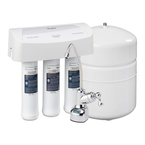
Reverse osmosis drinking water system
Hide thumbs
Also See for WHER25:
- User manual ,
- Operation manual (28 pages) ,
- Installation and operation manual (27 pages)
Table of Contents
Advertisement
Model WHER25
How to install, operate
and maintain your
Reverse Osmosis
Drinking Water System
Do not return unit to store
If you have any questions or concerns when
installing, operating or maintaining your reverse
osmosis system, call our toll free number:
1-866-986-3223
Monday- Friday, 8 AM - 7 PM EST or visit
www.whirlpoolwatertreatment.com
When you call, please be prepared to provide
the model, date code and serial number of your
product, found on the rating decal, located
inside the cover.
System tested and certified by NSF International
against NSF/ANSI Standards 42 & 58.
See performance data sheet for details.
Manufactured and warranted by
Ecodyne Water Systems
1890 Woodlane Drive
Woodbury, MN 55125
7322259 (Rev K 4/17/13)
Product No. 8576162B
Advertisement
Table of Contents

Related Manuals for Whirlpool WHER25


Summary of Contents for Whirlpool WHER25
- Page 1 Model WHER25 How to install, operate and maintain your Reverse Osmosis Drinking Water System Do not return unit to store If you have any questions or concerns when installing, operating or maintaining your reverse osmosis system, call our toll free number:...
-
Page 2: Table Of Contents
This warranty applies to consumer-owned installations only. ® / TM © 2013 Whirlpool. All rights reserved. Manufactured under license by Ecodyne Water Systems, Woodbury, Minnesota. -
Page 3: Specifications & Dimensions
Specifications & Dimensions Supply water pressure limits ..........40-100 psi (280-689 kPa) Supply water temperature limits . -
Page 4: Inspect Shipment
Inspect Shipment Your Reverse Osmosis Drinking Water System is Keep the small parts in the parts bag until you are shipped complete in one carton. Remove all items ready to install them. from your shipping carton. NOTE: Codes in the state of Massachusetts require Check all items against the packing list below. -
Page 5: Plan Your Installation
Plan Your Installation Read through the entire manual before beginning NOTE: For best system performance, the feed water your installation. Follow all steps exactly. Reading to the system should be softened or have hardness this manual will also help you get all the benefits less than 10 grains per gallon, with no iron. -
Page 6: Overview & Site Preparation
Overview and Site Preparation OVERVIEW PREPARE SITE FOR INSTALLATION 1. Before starting, close the hot and cold water shutoff Read through the entire manual before beginning your installation. valves (See Figure 6). There are seven steps to installing your Drinking Water 2. -
Page 7: Installation Instructions
Step A - Install Supply Water Fitting CHOOSE TYPE OF WATER FITTING TO INSTALL Check and comply with local plumbing codes as you plan, then install a cold feed (supply) water fitting. Refer to the Specifications page for supply water requirements. The fit- ting must provide a leak-tight connection to the RO 1/4"... -
Page 8: Step B - Install Reverse Osmosis Drain
Step B - Install RO Drain Under Sink INTRODUCTION Single trap Double Trap A suitable drain point is needed for the drain water from the Reverse Osmosis Filter. You have two options to choose from: Drain • Install the Drain Adapter included with your unit Adapter See Fig 7, Fig. - Page 9 Step B - Install RO Drain in Remote Location Outside Faucet (Hard Water) Outside Faucet BLUE Tubing (Hard Water) to Reverse Osmosis Faucet Soft, Cold Water Soft, Hot GREEN Tubing Soft water Water to Reverse to Reverse Osmosis System Shutoff Osmosis Valve System...
-
Page 10: Step C - Install Reverse Osmosis Filter Assembly
Step C - Install RO Filter Assembly INSTALL REVERSE OSMOSIS FILTER Hanger Washer (2) ASSEMBLY The Reverse Osmosis Filter Assembly is mounted on Screw (2) hanger washers. See Fig 12. The hanger washers allow you to lift the filter assembly from the washers without any hardware removal. - Page 11 Step E - Install RO Faucet SELECT LOCATION OF REVERSE OSMOSIS FAUCET MOUNTING HOLE You will need to select the location of the Reverse Osmosis Faucet. You have three options to choose from: • Use the existing sink top hole for the spray hose or soap dispenser (Must be 1-3/8”...
-
Page 12: Step E - Install Reverse Osmosis Faucet
Step E - Install RO Faucet (cont.) INSTALL REVERSE OSMOSIS FAUCET 1. Locate and organize your RO faucet install parts. Refer to Fig. 15. 2. Mount faucet base to sink hole until the faucet base is flat against the sink surface. The rubber gasket should be between the sink surface and the faucet base. -
Page 13: Cutting And Connecting The Tubes
Step F - Connect Tubes HOW TO CUT AND CONNECT THE TUBES Push-in Fitting Foam Plug Your Reverse Osmosis system includes push-in fittings for quick tubing connection. Review the following instructions before connecting the tubes in the next step. Failure to follow these instructions may lead to future leaks. -
Page 14: Step F - Connect Tubes
Step F - Connect Tubes (cont.) NOTE: Tubing lengths should allow for the removal of the assembly from the hanger washers for servicing. If tubing lengths are shortened for neater appearance, it may be necessary to keep the assembly on the hanger washers for service. -
Page 15: Step G - Sanitize, Pressure Test & Purge System
Step G - Sanitize, Test and Purge System SANITIZE THE SYSTEM Sanitizing is recommended immediately after installa- tion of the Reverse Osmosis system. It’s also recom- mended after servicing inner parts. It is important that the person installing or servicing the system have clean hands while handling inner parts of the system. -
Page 16: Pressure Test The System
Step G - Sanitize, Test and Purge System (cont.) PRESSURE TEST THE SYSTEM Reverse Osmosis NOTE: Complete the sanitizing procedures on the Kitchen Faucet Faucet preceding page before pressure testing. To pressure test the system, complete the following steps. 1. Open the water supply valve to the Reverse Osmosis system. -
Page 17: How Your Reverse Osmosis System Works
How Your RO Water System Works HOW YOUR REVERSE OSMOSIS SYSTEM Reverse Osmosis Faucet: The sink or countertop faucet has a hand operated knob to dispense drinking WORKS water. See Fig. 26. An air-gap is built into the faucet Introduction: Your Reverse Osmosis (RO) Drinking drain water connection to comply with plumbing Water System uses your household water pressure to codes. - Page 18 How Your RO Water System Works PRODUCT WATER FAUCET Air Gap PRODUCT WATER Gravity Drain DRAIN WATER Drain Flow AUTOMATIC Check Control SHUTOFF Valve WATER BLUE GREEN PRODUCT PREFILTER POSTFITLER WATER STORAGE YELLOW MEMBRANE FIG. 26 Reverse Osmosis Water Flow Schematic Water Flow Description 1.
-
Page 19: Maintenance
Maintenance PREFILTER / POSTFILTER MAINTENANCE Register for reminders to change filters NOTE: It is recommended to replace the battery, at www.whirlpoolwatertreatment.com prefilter and postfilter cartridges at least every 6 months of product water use. Replace more often if they begin to plug with sediment. The prefilter and postfilter are replaceable sediment cartridges with activated carbon in their composition. -
Page 20: Maintenance
Maintenance FLOW CONTROL Flow Control The flow control is required for proper operation of the Insert Reverse Osmosis system. See Fig. 28. The flow control, located inside the push-in elbow fitting on the drain port of Push-in Elbow Fitting the system housing, keeps water flowing through the mem- brane at the required rate. -
Page 21: Troubleshooting
Troubleshooting Problem: Chlorine taste and/or odor in the RO product water. Cause: The level of chlorine in your water supply Correction: If the water supply contains more than 2.0 ppm of chlorine, exceeds maximum limits, and has destroyed additional filtering of the water supply to the Reverse Osmosis the Reverse Osmosis membrane. -
Page 22: Exploded View & Parts List
Exploded View 1/4” red tubing 17 16 Questions? Call Toll Free 1-866-986-3223 Monday- Friday, 8 AM - 7 PM EST or visit www.whirlpoolwatertreatment.com When you call, please be prepared to provide the model, date code and serial number, found on the rating decal, located inside the cover. -
Page 23: Parts List
Parts List Part No. Description Part No. Description Mounting Hardware Kit WHEERF Pre & Post Filter Cartridge Ù – 7333129 (includes 2 ea. of Key Nos. 1 & 2) WHEERM RO Membrane Cartridge Ù Screw (2 req’d) 7205326 Storage Tank Hanger Washer (2 req’d) Tank Connector Kit –...