
Related Manuals for Husqvarna WH4817E, WH3615E


Summary of Contents for Husqvarna WH4817E, WH3615E
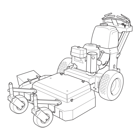
- Page 1 Operator's manual WH4817E/968999238 WH3615E/968999237 Please read the operator’s manual carefully and make sure you English understand the instructions before using the machine.
-
Page 3: Table Of Contents
OPERATOR’S MANUAL Contents Contents... 1 Introduction ... 3 Congratulations...3 General ...3 Driving and Transport on Public Roads ...3 Towing ...3 Operating ...3 Good Service ...4 Manufacturing Number ...4 Symbols and Decals ... 5 Safety Instructions... 7 General Use...7 Driving on Slopes...9 Children...10 Maintenance ...11 Transport...13... - Page 4 WARNING! Failure to follow cautious operating practices can result in serious injury to the operator or other persons. The owner must understand these instructions, and must allow only trained persons who understand these instructions to operate the mower. Each person operating the mower must be of sound mind and body and must not be under the influence of any mind altering substance.
-
Page 5: Introduction
Introduction Congratulations Thank you for purchasing a Husqvarna Walk-Behind Mower. This machine is built for the greatest efficiency and rapid mowing primarily of large areas. Controls in one place and a transmission regulated by steering controls contribute to the machine’s performance. -
Page 6: Good Service
Good Service Husqvarna’s products are sold all over the world and only in specialized retail stores with complete service. This ensures that you as a customer receive only the best support and service. Before the product is delivered, the machine has, for example, been inspected and adjusted by your retailer, see the certificate in the Service Journal in this operator’s manual. -
Page 7: Symbols And Decals
SYMBOLS AND DECALS Symbols and Decals These symbols are found on the machine and in the operator’s manual. Study them carefully so that you know what they mean. WARNING! Xxxxxxx xxxx xxxxxxxx xxx x Xxxxx xxxxxx xx. xx xxxxxxxx xxxxx xxx xx. Used in this publication to notify the reader of a risk of personal injury, particularly if the reader should neglect to follow instructions given in the manual. - Page 8 SYMBOLS AND DECALS Keep a safe distance from the machine. Moving sharp blades Read under cover. Operator´s Manual. Whole body exposure to thrown objects. English- Severing of fingers & toes. Rotating blades. Shut off engine & remove key before performing any maintenance or repair work.
-
Page 9: Safety Instructions
SAFETY INSTRUCTIONS Safety Instructions These instructions are for your safety. Read them carefully. WARNING! This symbol means that important safety instructions need to be emphasized. It concerns your safety. General Use • Read all instructions in this operator’s manual and on the machine before starting it. - Page 10 SAFETY INSTRUCTIONS • Shut down the blades when not mowing. • Be careful when turning around fixed objects, so that the blades do not hit them. Never drive over foreign objects. • Only use the machine in daylight or in other well-lit conditions.
-
Page 11: Driving On Slopes
SAFETY INSTRUCTIONS Driving on Slopes Driving on slopes is one of the operations where the risk is greatest that the driver will lose control or the machine will tip over, which can result in serious injury or death. All slopes require extra caution. If you cannot reverse up a slope or if you feel unsure, do not mow the slope. -
Page 12: Children
SAFETY INSTRUCTIONS Children • Serious accidents may occur if you fail to be on guard for children in the vicinity of the machine. Children are often attracted to the machine and mowing work. Never assume that children will stay put where you last saw them. -
Page 13: Maintenance
SAFETY INSTRUCTIONS Maintenance WARNING! The engine must not be started when the protective plate for the mower deck’s drive belt is removed. • Stop the engine. Prevent the engine from starting by removing the spark plug cables from the spark plugs or by removing the ignition key before making any adjustments or performing maintenance. - Page 14 • Safety decals should be replaced if they are missing or illegible. Decals can be purchased from your Husqvarna dealer. English- Use protective glasses at maintenance work. Never drive the machine in an enclosed space...
-
Page 15: Transport
(if any). If a spark arrester is used, it should be maintained in effective working order by the operator. A spark arrester for the muffler is available through your authorized Husqvarna dealer. IMPORTANT INFORMATION The parking brake is not sufficient to lock the machine in place during transport. -
Page 16: Controls
Controls This operator’s manual describes the Husqvarna Walk-Behind Mowers WH3615E and WH4817E. The machines are fitted with a Kawasaki four-stroke V-Twin engine, see Technical Data on page 56. Transmission from the engine is made via two IZT gears, one for each wheel. -
Page 17: Recoil Starter Grip
Pull the recoil starter grip slowly until you feel compression, then pull it briskly. Normally this engine will not backfire. If you get backfires, contact your Husqvarna dealer for service. 2. Ground Speed Lever Located in the center of the console. Controls the forward speed of the mower. -
Page 18: Motion Control Levers
3. Motion control levers The machine’s speed and direction are continuously variable using the two motion control levers. When both controls are in the neutral position, the machine stands still. The controls can be locked in neutral position by the Neutral bail By moving both controls an equal amount the machine moves in a straight line forward. -
Page 19: Operator Presence Lever
CONTROLS 5. Operator Presence Lever Located on the handle. As an additional safety feature, these mowers are equipped with an Operators Presence System. This is an electrical interlock safety system which is activated by depressing either one or both of the Operator Presence Levers at the handle grips. -
Page 20: Brake/Bypass Lever
7. Brake/Bypass Lever Located at the back of the rear deck. Used to apply park brake or bypass the IZT gears for free wheel (neutral) condition. The functions for the lever is: Drive, used when operating the machine. Parking, parking brake applied. Bypass, used when moving the machine by hand. -
Page 21: Neutral Bail
CONTROLS 9. Neutral Bail Keeps the unit from moving while idling. The neutral bail will lock the motion control levers in neutral position and must be activated when starting the engine. To engage the neutral bail, pull the Ground Speed Lever fully back and press up the bail into position, see illustration. -
Page 22: Hour Meter
CONTROLS 11. Hour Meter The hour meter displays the total operating time. It will flash CHG OIL (Change Oil) at 50 hour intervals. The flash duration is one hour before and one hour after the interval. The CHG OIL icon will come on and shut off automatically. -
Page 23: Refueling
13. Refueling The machine has one fuel tank. The tank volume is 5.3 gallons / 20 liters. The engine shall be run on a minimum of 87-octane unleaded gasoline (no oil mix). See Technical Data concerning methanol and ethanol fuels. WARNING! Gasoline is highly flammable. -
Page 24: Fuel Shut-Off Valve
14. Fuel Shut-off Valve The fuel shut-off valve is placed on the fuel line below the fuel tank. The valve has two positions; ON and OFF. The illustration shows the valve in the closed OFF position. IMPORTANT INFORMATION Close fuel valve at the end of each mowing job. -
Page 25: Operation
Operation WARNING! Be thoroughly familiar with all controls their function and how to operate them before operating the mower. Before Starting • Read the sections Safety Instructions, page 6, and Presentation, page 14, before starting the machine. • Perform the daily maintenance before starting (see “Maintenance Schedule”... -
Page 26: Starting The Engine
Starting the Engine WARNING! Never run the engine indoors, in enclosed or poorly ventilated spaces. Engine exhaust fumes contain poisonous carbon monoxide. Make sure that the blades are disengaged. Check that the neutral bail is locked. Set the fuel valve to the ON position. English- OPERATION Blades disengaged... - Page 27 Adjust choke (if needed) Do not use choke when the engine is warm. Turn ignition key to ON position. IMPORTANT INFORMATION Do not let recoil cord snap back by itself. This may damage the cord or the recoil starter assembly. Pull the recoil starter grip slowly until you feel compression, then pull it briskly.
-
Page 28: Driving Forward
Holding down at least one of the operator presence levers, engage blades and set RPM to maximum. Release the neutral bail. 10. Set the ground speed lever to the desired position. Driving forward Pull the ground speed lever fully back. Depress one operator presence lever. -
Page 29: Reversing
Reversing Depress one operator presence lever and pull the ground speed lever fully back. Unlock the motion control levers by pushing the neutral bail down out of the neutral slots. Slowly push both motion control levers towards the handle at the same time to begin a straight line backward motion. -
Page 30: Mowing Tips
Mowing Tips • Observe and mark rocks and other fixed objects in order to avoid collisions. • The cutting deck should be properly leveled for best mowing performance. The blades should be parallel to the ground or slightly tipped down in the front. -
Page 31: Stopping
• Avoid mowing wet lawns. The mowing result is poorer because the wheels sink into the soft lawn, clumps build, and the grass clippings fasten under the cowling. • Hose the mower deck with water after each use. Hose especially underneath. •... -
Page 32: Stopping The Engine
Stopping the Engine Allow the engine to idle a minute in order to attain normal operating temperature before stopping it, if it has been worked hard. Avoid idling the engine for longer periods, as there is a risk of the spark plugs fouling. Disengage the blades by depressing the blade switch. -
Page 33: Cutting Height Adjustment
Moving spacers between the upper side and the lower side of the blades according to "Cutting height table". For removing and installation of blades, contact your Husqvarna dealer. • Cutting deck height adjustment according to the following instruction. Before changing cutting heights make sure the blades are off, key switch is off, and remove spark plug wires. - Page 34 Tip the handles up or down until the correct position is achieved. See "Cutting height table", or reference the height decal located on the muffler side of the rear deck. Reinstall and tighten the outer three bolts on each side. A tapered punch may be needed to help align the holes.
-
Page 35: Moving By Hand
Moving by hand IMPORTANT INFORMATION not tow this machine, it may cause damage to the drive system. When pushing or pulling the mower, be sure to move brake/bypass lever to the bypass position. Brake/bypass lever is located on the back of the rear deck. -
Page 36: Maintenance
Maintenance Maintenance Schedule The following is a list of maintenance procedures that must be performed on the machine. For those points not described in this manual, visit an authorized service workshop. An annual service carried out by an authorized service workshop is recommended in order to maintain your machine in the best possible condition and to ensure safe operation. - Page 37 Maintenance Check/adjust the cutting height Check throttle and choke cables Clean the air cleaner’s pre-filter (foam) Clean the air cleaner’s filter cartridge (paper filter) Change the engine oil (every 200 hours) Replace the engine oil filter (every 200 hours) Clean/Replace the spark plugs Replace the fuel filter Clean the cooling fins Check the engine valve clearance...
-
Page 38: Ignition System
Ignition System The engine is equipped with an electronic ignition system. Only the spark plugs require maintenance. For recommended spark plugs, see Technical Data. Remove the ignition cable boot and clean around the spark plug. Remove the spark plugs with a spark plug socket wrench. -
Page 39: Checking The Safety System
Checking the Safety System The machine is equipped with a safety system that prevents starting or driving under the following conditions. The engine can only be started when: The blades are disengaged. The neutral bail must be in the locked position. -
Page 40: Checking And Adjusting The Choke Cable
Checking and Adjusting the Throttle Cable Check that the engine responds to throttle increases and that a good engine speed is attained at full throttle. If doubts arise, contact the service workshop. If adjustments are necessary, they can be made as follows for the lower cable: Loosen the clamping screw for the cable’s outer casing and move the throttle to the full throttle position. -
Page 41: Replacing The Air Filter
Replacing the Air Filter If the engine seems weak or runs unevenly, the air filter may be clogged. If run with a dirty air filter, the spark plugs can become fouled, disrupting operation. For this reason, it is important to replace the air filter regularly (see the heading Maintenance Schedule for the proper service interval). -
Page 42: Replacing The Fuel Filter
Replacing the Fuel Filter Replace the line-mounted fuel filter every 100 hours (once per season) or more regularly if it is clogged. Replace the filter as follows: Move the hose clamps away from the filter. Use flat-nosed pliers. Pull the filter loose from the hose ends. Push the new filter into the hose ends. -
Page 43: Checking The Parking Brake
Perform a stand still test and check that there is sufficent braking action. To adjust the handbrake, contact the Husqvarna service workshop. Checking the V-belts Deck belt Check every 100 hours of operation. Check for severe cracking and large nicks. -
Page 44: Checking The Blades
Checking the Blades In order to attain the best mowing effect, it is important that the blades are well sharpened and not damaged. Bent or cracked blades or blades with large nicks in should be replaced. Check the blade mounts. IMPORTANT INFORMATION The replacement or sharpening of blades should be carried out by an authorized... -
Page 45: Cleaning And Washing
Cleaning and Washing Regular cleaning and washing, especially under the mower deck, will increase the machine’s lifespan. Make it a habit to clean the machine directly after use, before the dirt sticks. Do not spray high pressure water directly on the top of deck spindles. Caster Wheels Check every 200 hours. -
Page 46: Blade Replacement
• Install and tighten blade bolt securely. Tightening torque 90 ft/lb (122 Nm). IMPORTANT INFORMATION Special blade bolt is heat treated. Replace with a Husqvarna bolt if required. Do NOT use lower grade hardware than specified. English- MAINTENANCE Blade Center hole... -
Page 47: Lubrication
Lubrication Lubrication Schedule 12/12 1/52 1/365 Lubrication schedule Lubricate with grease gun 12/12 Every year 1/52 Every week 1/365 Every day General Remove the ignition key to prevent unintentional movements during lubrication. When lubricating with an oil can, it should be filled with engine oil. When lubricating with grease, unless otherwise stated, with a high grade molybdenum disulfide grease or another chassis or ball bearing grease offering good corrosion protection should be used. -
Page 48: Lubricating The Cables
Lubricating the Cables If possible, lubricate both ends of the cables and move the controls to end stop positions when lubricating. Refit the rubber covers on the cables after lubrication. Cables with sheaths will bind if they are not lubricated regularly. If a cable binds, it can disrupt operation. If a cable binds, remove the cable and hang it vertically. - Page 49 4. Belt Adjuster, Mower Deck Remove the plate (four screws) and lubricate with a grease gun, one zerk, until grease is forced out. Use only good quality molybdenum disulphide grease. Grease from well-known brand names (petrochemical companies, etc.) usually maintains a good quality. IMPORTANT INFORMATION Be spartan and remove excess lubricant so that is does not come into contact with...
- Page 50 6. Changing the Oil Filter Drain the engine oil in accordance with the description under the heading Engine Oil/Change Engine Oil. Disassemble the oil filter. If necessary, use a filter remover. Wipe new, clean engine oil onto the seal of the new filter. Mount the filter by hand with + 3/4 turn.
- Page 51 Transmission Gears The gears are maintenance free. There is no need to check the level or change the oil. If a leak occurs, replace the unit or contact your Husqvarna dealer. LUBRICATION Remove the dipstick The dipstick markings Engine oils...
-
Page 52: Trouble Shooting Guide
TROUBLE SHOOTING GUIDE Trouble Shooting Guide Problem The engine will not start. The engine runs unevenly. The engine seems weak. English- Cause • The control for engaging the mower deck is in engaged position. • The motion control are not locked in the neutral position by the neutral bail. - Page 53 TROUBLE SHOOTING GUIDE The engine overheats. The machine moves slowly, unevenly, or not at all. Mower deck not engaging. Uneven mowing results. The machine vibrates. The machine moves when in neutral postion.•The motion control linkage out of adjustment. • Clogged air intake or cooling fins. •...
- Page 54 TROUBLE SHOOTING GUIDE The machine pulls left or right.•The tire pressure uneven. English- • The motion control linkage incorrectly adjusted. • Soft terrian. • Slope to steep. • The tracking not adjusted. • The bypass misadjusted on one side.
-
Page 55: Storage
Service When ordering spare parts, please specify the purchase year, model, type, and serial number. Always use genuine Husqvarna spare parts. An annual check-up at an authorized service workshop is a good way to ensure that your machine performs its best the following season. -
Page 56: Wiring Diagrams
Wiring diagrams English- WIRING DIAGRAM Left operator presence lever Electric clutch Neutral switch Right operator presence lever Ignition. #10 Screw type fork terminal Module connector Plated terminals. Clutch fuse Packard connector Hour meter 8011-696... - Page 57 WIRING DIAGRAMS Left operator presence switch Hour meter Electric clutch switch Neutral Right operator switch #10 screw type fork terminal Module connector Clutch Connector 8011-697 English-...
-
Page 58: Technical Data
Technical Data WH3615E Engine Manufacturer Kawasaki Type FH430V Power 15 hp / 12.5 kW Spark plugs / gap RCJ8Y/ .030” / 0.75 mm Oil capacity excl filter 1.6 qt / 1.5 liters Oil capacity incl filter 1.8 qt / 1.7 litres Engine oil SAE 10W30, 10W40 (See viscocity digram) -
Page 59: Torque Specifications
WH3615E Overall dimensions Weight 460 lbs / 209 kg Base maschine lenght 75” / 191 cm Base machine width 47” / 119 cm Base machine height 42” /106 cm Overall width, Chute up 37” / 94 cm Overall width, Chute down 47”... -
Page 60: Conformity Certificates
CONFORMITY CERTIFICATES Conformity Certificates USA requirements Labels are placed on the engine and/or in the engine compartment stating that the machine will fulfill the requirements. This is also applicable to special requirements for any of the states, (Californian emission rules etc.). Do not remove any of these labels. Certificates can also be supplied with the machine at delivery or written in the Engine manual. -
Page 61: Service Journal
Service Journal Action Delivery Service Mount the caster wheels. Adjust the tire pressure of all wheels to 1 bar (15 PSI). Check that the right amount of oil is in the engine. Adjust the position of the steering controls. Fill with fuel and open the fuel shut-off valve. Connect the exhaust fumes extractor. -
Page 62: 25-Hour Service
Action 25-Hour Service Check the fuel pump’s air filter. Check the tire pressures. Lubricate the belt adjuster, mower deck. Check/clean the engine’s cooling air intake. Clean the air cleaner’s pre-filter (foam). Inspect/Replace blades. English- SERVICE JOURNAL Date, mtr reading, stamp, sign... -
Page 63: 50-Hour Service
SERVICE JOURNAL Action 50-Hour Service Perform the 25-hour service. Clean/replace the air cleaner’s filter cartridge (paper filter) (shorter intervals for dusty operating conditions). Check/adjust the parking brake. Lubricate the front wheel bearings. Lubricate outer belt wheels. Lubricate throttle and choke cables. Date, mtr reading, stamp, sign English-... -
Page 64: 100-Hour Service
Action 100-Hour Service Perform the 25-hour service. Perform the 50-hour service. Change engine oil. Check whether the engine oil filter needs changing (every 200 hours). Clean/replace the spark plugs. Replace the fuel filter. Clean the cooling fins on the engine and transmission. Check V-belts pulleys etc. -
Page 65: 300-Hour Service
SERVICE JOURNAL Action 300-Hour Service Inspect the machine. Come to agreement with the customer as to which additional work is to be carried out. Perform the 25-hour service. Perform the 50-hour service. Perform the 100-hour service. Clean the combustion chamber and grind the valve seats. Check the engine valve clearance. -
Page 66: At Least Once Each Year
Action At Least Once Each Year Clean the engine’s cooling air intake (25 hours). Replace the air cleaner’s pre-filter (foam) (200 hours). Replace the air filter’s paper cartridge (200 hours). Change the engine oil (100 hours). Replace the engine oil filter (200 hours). Check/adjust the cutting height. - Page 68 110569R01 07/26/05...