D-Link xStack DES-3200 Series Installation Manual
Layer 2 managed fast ethernet switch
Hide thumbs
Also See for xStack DES-3200 Series:
- Reference manual (647 pages) ,
- Hardware installation manual (60 pages) ,
- Reference manual (303 pages)

Related Manuals for D-Link xStack DES-3200 Series


Summary of Contents for D-Link xStack DES-3200 Series
- Page 1 xStack® DES-3200 Series Layer 2 Managed Fast Ethernet Switch Hardware Installation Guide...
- Page 2 © 2012 D-Link Corporation. All rights reserved. Reproduction in any manner whatsoever without the written permission of D-Link Corporation is strictly forbidden. Trademarks used in this text: D-Link and the D-LINK logo are trademarks of D-Link Corporation; Microsoft and Windows are registered trademarks of Microsoft Corporation.
-
Page 3: Table Of Contents
xStack® DES-3200 Series Layer 2 Managed Fast Ethernet Switch Hardware Installation Guide Table of Contents Intended Readers ..............................iii Typographical Conventions..............................iii Notes, Notices, and Cautions..............................iii Safety Instructions ................................... iii Safety Cautions..................................iv General Precautions for Rack-Mountable Products ........................v Protecting Against Electrostatic Discharge ..........................v Chapter 1 Introduction ............................ -
Page 4: Intended Readers
xStack® DES-3200 Series Layer 2 Managed Fast Ethernet Switch Hardware Installation Guide Intended Readers Typographical Conventions Notes, Notices, and Cautions Safety Instructions Safety Cautions General Precautions for Rack-Mountable Products Protecting Against Electrostatic Discharge The DES-3200 Series Hardware Installation Guide contains detailed information about the hardware specifications of a Switch in this series. -
Page 5: Safety Cautions
xStack® DES-3200 Series Layer 2 Managed Fast Ethernet Switch Hardware Installation Guide Safety Cautions To reduce the risk of bodily injury, electrical shock, fire, or damage to the equipment, observe the following precautions. Observe and follow service markings. Do not service any product except as explained in your system documentation. Opening or removing covers that are marked with the triangular symbol with a lightning bolt may expose you to electrical shock. -
Page 6: General Precautions For Rack-Mountable Products
xStack® DES-3200 Series Layer 2 Managed Fast Ethernet Switch Hardware Installation Guide If the system has multiple sources of power, disconnect power from the system by unplugging all power cables from the power supplies. Move products with care; ensure that all casters and/or stabilizers are firmly connected to the system. Avoid sudden stops and uneven surfaces. -
Page 7: Chapter 1 Introduction
xStack® DES-3200 Series Layer 2 Ethernet Managed Switch Hardware Installation Guide Chapter 1 Introduction Switch Description Front Panel Description Rear Panel Description Side Panel Description Gigabit Combo Ports Switch Description The DES-3200 Series Hardware Installation Guide describes the hardware installation and specifications concerning the DES-3200 Series switches. -
Page 8: Front Panel Description
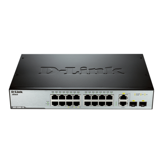
xStack® DES-3200 Series Layer 2 Ethernet Managed Switch Hardware Installation Guide 10/100/1000Mbps Copper / 100/1000Mbps SFP Ports, Two 10/100/1000Mbps Copper Ports, and One RJ-45 Console Port for out-of-band CLI configuration. DES-3200-28/ME Twenty-four 10/100Mbps Copper Ports, Two Combo 10/100/1000Mbps Copper / 100/1000Mbps SFP Ports, Two 100/1000Mbps SFP Ports, One RJ-45 Console Port for out-of-band CLI configuration, and One Alarm Connector Port. - Page 9 xStack® DES-3200 Series Layer 2 Ethernet Managed Switch Hardware Installation Guide Sixteen 10/100Mbps Copper Ports One Combo 10/100/1000Mbps Copper / 100/1000Mbps SFP port One 100/1000Mbps SFP Port One RJ-45 Console Port LEDs for Power, Console, Link/Act for port 1 to 16, and Link/Act/Speed for port 17 and 18 Figure 1-3.
- Page 10 xStack® DES-3200 Series Layer 2 Ethernet Managed Switch Hardware Installation Guide Figure 1-6. Front Panel of the DES-3200-26-DC The front panel of the DES-3200-28 switch consists out of the following: Twenty-four 10/100Mbps Copper Ports Two Combo 10/100/1000Mbps Copper / 100/1000Mbps SFP ports ...
- Page 11 xStack® DES-3200 Series Layer 2 Ethernet Managed Switch Hardware Installation Guide Figure 1-10. Front Panel of the DES-3200-28/ME The front panel of the DES-3200-52 switch consists out of the following: Forty-eight 10/100Mbps Copper Ports Two Combo 10/100/1000Mbps Copper / 100/1000Mbps SFP ports ...
-
Page 12: Led Indicators
xStack® DES-3200 Series Layer 2 Ethernet Managed Switch Hardware Installation Guide LED Indicators The Switch supports LED indicators for Power, Console, Fan, and Link/Act or Link/Act/Speed for each port. The following shows the LED indicators for the DES-3200 Series along with an explanation of each indicator. Figure 1-14. - Page 13 xStack® DES-3200 Series Layer 2 Ethernet Managed Switch Hardware Installation Guide Figure 1-17. LED Indicators on DES-3200-18-DC Figure 1-18. LED Indicators on DES-3200-26 Figure 1-19 LED Indicators on DES-3200-26-DC Figure 1-20. LED Indicators on DES-3200-28...
- Page 14 xStack® DES-3200 Series Layer 2 Ethernet Managed Switch Hardware Installation Guide Figure 1-21. LED Indicators on DES-3200-28F Figure 1-22. LED Indicators on DES-3200-28P Figure 1-23. LED Indicators on DES-3200-28/ME Figure 1-24. LED Indicators on DES-3200-52...
- Page 15 xStack® DES-3200 Series Layer 2 Ethernet Managed Switch Hardware Installation Guide Figure 1-25. LED Indicators on DES-3200-52-DC Figure 1-26. LED Indicators on DES-3200-52P Location LED Indicative Color Status Description Solid Light Power on. Power Green Light off Power off. Solid Light Console on.
- Page 16 xStack® DES-3200 Series Layer 2 Ethernet Managed Switch Hardware Installation Guide Solid Green When there is a secure 1000Mbps Ethernet connection (or link) at any of the ports. Blinking Green When there is reception or transmission (i.e. Activity—Act) of data occurring at a 1000Mbps Ethernet connected port.
-
Page 17: Rear Panel Description
xStack® DES-3200 Series Layer 2 Ethernet Managed Switch Hardware Installation Guide Rear Panel Description The rear panel of the Switch contains an AC or DC power connector. The AC power connector is a standard three- pronged connector that supports the power cord. Plug-in the female connector of the provided power cord into this socket, and the male side of the cord into a power outlet. - Page 18 xStack® DES-3200 Series Layer 2 Ethernet Managed Switch Hardware Installation Guide Figure 1-33. Rear panel view of the DES-3200-28 Figure 1-34. Rear panel view of the DES-3200-28F Figure 1-35. Rear panel view of the DES-3200-28P Figure 1-36. Rear panel view of the DES-3200-28/ME Figure 1-37.
-
Page 19: Side Panel Description
xStack® DES-3200 Series Layer 2 Ethernet Managed Switch Hardware Installation Guide Side Panel Description The left- and right-hand panels of the Switch have heat vents to dissipate heat. Do not block these openings, and leave at least 6 inches of space at the rear and sides of the Switch for proper ventilation. Be reminded that without proper heat dissipation and air circulation, system components might overheat, which could lead to system failure Figure 1-40. - Page 20 xStack® DES-3200 Series Layer 2 Ethernet Managed Switch Hardware Installation Guide Figure 1-43. Side panels of the DES-3200-18-DC Figure 1-44. Side panels of the DES-3200-26 Figure 1-45. Side panels of the DES-3200-26-DC Figure 1-46. Side panels of the DES-3200-28...
- Page 21 xStack® DES-3200 Series Layer 2 Ethernet Managed Switch Hardware Installation Guide Figure 1-47. Side panels of the DES-3200-28F Figure 1-48. Side panels of the DES-3200-28P Figure 1-49. Side panels of the DES-3200-28/ME Figure 1-50. Side panels of the DES-3200-52...
-
Page 22: Gigabit Combo Ports
xStack® DES-3200 Series Layer 2 Ethernet Managed Switch Hardware Installation Guide Figure 1-51. Side panels of the DES-3200-52-DC Figure 1-52. Side panels of the DES-3200-52P Gigabit Combo Ports The DES-3200 Series features either two or four Gigabit Ethernet Combo ports. These ports are 1000BASE-T copper ports (optional) and Small Form Factor Portable (SFP) ports (optional). - Page 23 xStack® DES-3200 Series Layer 2 Ethernet Managed Switch Hardware Installation Guide Figure 1- 27. Installing the SFP Module The Switch is equipped with SFP ports, which are to be used with fiber-optical transceiver cabling in order to uplink various other networking devices for a gigabit link that may span great distances. For a full list of supported SFP transceivers, for this switch series, refer to the Appendix A.
-
Page 24: Chapter 2 Installation
Quick Installation Guide This manual on CD, including a D-View trial version If any item is missing or damaged, please contact your local D-Link Reseller for replacement. Before You Connect to the Network The site where you install the Switch may greatly affect its performance. Please follow these guidelines for setting up the Switch. -
Page 25: Installing The Switch Without The Rack
xStack® DES-3200 Series Layer 2 Ethernet Managed Switch Hardware Installation Guide Installing the Switch without the Rack When installing the Switch on a desktop or shelf, the rubber feet included with the Switch should first be attached. Attach these cushioning feet on the bottom at each corner of the device. Allow enough ventilation space between the Switch and any other objects in the vicinity. -
Page 26: Mounting The Switch In A Standard 19" Rack
xStack® DES-3200 Series Layer 2 Ethernet Managed Switch Hardware Installation Guide Mounting the Switch in a Standard 19" Rack CAUTION: Installing systems in a rack without the front and side stabilizers installed could cause the rack to tip over, potentially resulting in bodily injury under certain circumstances. Therefore, always install the stabilizers before installing components in the rack. -
Page 27: Alarm Connector (Des_3200-28/Me Only)
xStack® DES-3200 Series Layer 2 Ethernet Managed Switch Hardware Installation Guide Figure 2-4. Close-up view of Power Receptacle 1. The DC power supply has a three-terminal wiring block consisting of a positive (+), a negative (-) and a safety ground terminal. 2. - Page 28 xStack® DES-3200 Series Layer 2 Ethernet Managed Switch Hardware Installation Guide Alarm Connector Port Contact Description Output. Normal Closed Pin. (42VAC or 60VDC) Output. Common Pin. (42VAC or 60VDC) Output. Normal Open Pin. (42VAC or 60VDC) Input 2. Input 2. Input 1.
-
Page 29: Chapter 3 Connecting The Switch
xStack® DES-3200 Series Layer 2 Ethernet Managed Switch Hardware Installation Guide Chapter 3 Connecting the Switch Switch to End Node Switch to Hub or Switch NOTE: All 10/100/1000Mbps NWay Ethernet ports can support both MDI-II and MDI-X connections. Switch to End Node End node is a generic name for edge networking devices that are connected to the Switch. -
Page 30: Switch To Hub Or Switch
xStack® DES-3200 Series Layer 2 Ethernet Managed Switch Hardware Installation Guide Switch to Hub or Switch These connections can be accomplished in a number of ways using a normal cable. A 10BASE-T hub or switch can be connected to the Switch via a twisted-pair Category 3, 4, 5 or 5e UTP/STP cable. -
Page 31: Chapter 4 Introduction To Switch Management
xStack® DES-3200 Series Layer 2 Ethernet Managed Switch Hardware Installation Guide Chapter 4 Introduction to Switch Management Management Options Web-based Management Interface SNMP-Based Management Connecting the Console Port First Time Connecting to the Switch Password Protection SNMP Settings IP Address Assignment Management Options This system may be managed out-of-band through the console port on the front panel or in-band using Telnet. -
Page 32: First Time Connecting To The Switch
DES-3200-28P Fast Ethernet Switch Command Line Interface Firmware: Build 4.04.003 Copyright(C) 2012 D-Link Corporation. All rights reserved. UserName: Figure 4-1. Initial screen after first connection First Time Connecting to the Switch The Switch supports user-based security that can allow you to prevent unauthorized users from accessing the Switch or changing its settings. -
Page 33: Password Protection
DES-3200 Series Layer 2 Ethernet Managed Switch Hardware Installation Guide DES-3200-28P Fast Ethernet Switch Command Line Interface Firmware: Build 4.04.003 Copyright(C) 2012 D-Link Corporation. All rights reserved. UserName: PassWord: DES-3200-28P:admin# Figure 4-2. Command Prompt NOTE: The first user automatically gets Administrator level privileges. It is recommended to create at least one Admin-level user account for the Switch. -
Page 34: Snmp Settings
xStack® DES-3200 Series Layer 2 Ethernet Managed Switch Hardware Installation Guide NOTICE: In case of lost passwords or password corruption, please refer to the section titled “Password Recovery Procedure” in Appendix B of the CLI Reference Guide” which will guide you through the steps necessary to resolve this issue. -
Page 35: Ip Address Assignment
xStack® DES-3200 Series Layer 2 Ethernet Managed Switch Hardware Installation Guide own proprietary enterprise MIB as an extended Management Information Base. Specifying the MIB Object Identifier may also retrieve the proprietary MIB. MIB values can be either read-only or read-write. IP Address Assignment Each Switch must be assigned its own IP Address, which is used for communication with an SNMP network manager or other TCP/IP application (for example BOOTP, TFTP). - Page 36 xStack® DES-3200 Series Layer 2 Ethernet Managed Switch Hardware Installation Guide Alternatively, you can enter config ipif System ipaddress xxx.xxx.xxx.xxx/z. Where the x's represent the IP address to be assigned to the IP interface named System and the z represents the corresponding number of subnets in CIDR notation.
-
Page 37: Chapter 5 Web-Based Switch Configuration
xStack® DES-3200 Series Layer 2 Ethernet Managed Switch Hardware Installation Guide Chapter 5 Web-based Switch Configuration Introduction Login to Web manager Web-Based User Interface Introduction All software functions of the Switch can be managed, configured and monitored via the embedded web-based (HTML) interface. -
Page 38: Web-Based User Interface
Function Area 1 Select the folder or window to be displayed. The folder icons can be opened to display the hyperlinked window buttons and subfolders contained within them. Click the D-Link logo to go to the D-Link website. Area 2 Presents a graphical near real-time image of the front panel of the Switch. -
Page 39: Web Pages
xStack® DES-3200 Series Layer 2 Ethernet Managed Switch Hardware Installation Guide Web Pages When you connect to the management mode of the Switch with a Web browser, a login window is displayed. Enter a user name and password to access the Switch's management mode. When connecting to the management mode of the Switch with a web browser, a login screen is displayed. -
Page 40: Appendix A - Technical Specifications
xStack® DES-3200 Series Layer 2 Ethernet Managed Switch Hardware Installation Guide Appendix A – Technical Specifications General Protocols IEEE 802.3 10BASE-T Ethernet IEEE 802.3u 100BASE-TX Fast Ethernet IEEE 802.3ab 1000BASE-T Gigabit Ethernet IEEE 802.3z 1000BASE-X (SFP “Mini GBIC”) IEEE 802.1D Spanning Tree IEEE 802.1w Rapid Spanning Tree Protocol IEEE 802.1s Multiple Spanning Tree Protocol IEEE 802.1Q VLAN... - Page 41 xStack® DES-3200 Series Layer 2 Ethernet Managed Switch Hardware Installation Guide DES-3200-18-DC - Sixteen 10/100Mbps Copper Ports, One 100/1000Mbps SFP Port, One Combo 10/100/1000Mbps Copper / 100/1000Mbps SFP Port. DES-3200-26 - Twenty-four 10/100Mbps Copper Ports, Two Combo 10/100/1000Mbps Copper / 100/1000Mbps SFP Ports. DES-3200-26-DC - Twenty-four 10/100Mbps Copper Ports, Two Combo 10/100/1000Mbps Copper / 100/1000Mbps SFP Ports.
- Page 42 xStack® DES-3200 Series Layer 2 Ethernet Managed Switch Hardware Installation Guide DES-3200-52: One fan DES-3200-52-DC: One fan DES-3200-52P: Four Fans The other switches in this series are Fanless. Operating Temperature -5 - 50°C Storage Temperature -40 - 70°C MTBF DES-3200-10: 738,787.9883 hours DES-3200-10-DC: 931,568.559 hours DES-3200-18: 670,243 hours DES-3200-18-DC: 825,160 hours...
- Page 43 xStack® DES-3200 Series Layer 2 Ethernet Managed Switch Hardware Installation Guide Performance Transmission Method Store-and-forward Packet Buffer 1.5MB per device Packet Filtering/ 14,881 pps (10M port) Forwarding Rate 148,810 pps (100M port) 1,488,100 pps (1Gbps port) MAC Address Learning Automatic update. Supports 16K MAC address Priority Queues 8 Priority Queues per port Forwarding Table Age...
- Page 44 xStack® DES-3200 Series Layer 2 Ethernet Managed Switch Hardware Installation Guide Blinking Amber When there is reception or transmission (i.e. Activity—Act) of data occurring at a 10/100Mbps Ethernet connected port. Light off No link. LED Per Solid Green Power feeding. 10/100Mbps Port in Green Blinking Green Error Condition...
- Page 45 xStack® DES-3200 Series Layer 2 Ethernet Managed Switch Hardware Installation Guide 100Mbps SFP Ports Compliant to the following standards: (DES-3200-28F Only) IEEE 802.3 compliance IEEE 802.3u compliance Support Full-Duplex operations IEEE 802.3x flow control support in full-duplex mode SFP (Mini GBIC) Support: DEM-210 (100BASE-FX, Single-mode, 15km) DEM-211 (100BASE-FX, Multi-mode, 2km) DEM-220T (TX-1550/RX-1310nm, Single-mode, 20km)
-
Page 46: Appendix B - Cables And Connectors
xStack® DES-3200 Series Layer 2 Ethernet Managed Switch Hardware Installation Guide Appendix B – Cables and Connectors Ethernet Cable When connecting the Switch to another switch, a bridge or hub, a normal cable is necessary. Please review these products for matching cable pin assignment. The following diagrams and tables show the standard RJ-45 receptacle/connector and their pin assignments. -
Page 47: Console Cable
xStack® DES-3200 Series Layer 2 Ethernet Managed Switch Hardware Installation Guide Console Cable When connecting the Switch a PC, a Console cable is necessary. The following diagrams and tables show the standard Console-to-DJ-45 receptacle/connector and their pin assignments. Figure B- 2. Console-to-RJ-45 Cable Console-RJ-45 Pin Assignments Console (DB9/RS232) RJ-45... -
Page 48: Appendix C - Module Specs And Cable Lengths
xStack® DES-3200 Series Layer 2 Ethernet Managed Switch Hardware Installation Guide Appendix C – Module Specs and Cable Lengths Use the following table to as a guide for the module specs and maximum cable lengths. Standard Media Type Maximum Distance 1000BASE-LX, Single-mode fiber module 10km 1000BASE-SX, Multi-mode fiber module... -
Page 49: Warranty & Technical Support
The customer must submit with the product as part of the claim a written description of the Hardware defect or Software nonconformance in sufficient detail to allow D-Link to confirm the same, along with proof of purchase of the product (such as a copy of the dated purchase invoice for the product) if the product is not registered. - Page 50 D-Link Corporation/D-Link Systems, Inc., as stipulated by the United States Copyright Act of 1976 and any amendments thereto. Contents are subject to change without prior notice. Copyright 2004 by D-Link Corporation/D-Link Systems, Inc.
-
Page 51: Product Registration
Product Registration Register your D-Link product online at http://support.dlink.com/register/ Product registration is entirely voluntary and failure to complete or return this form will not diminish your warranty rights. -
Page 52: Technical Support
You can find software updates and user documentation on the D- Link website. D-Link provides free technical support for customers within the United States and within Canada for the duration of the service period, and warranty confirmation service, during the warranty period on this product. - Page 53 Technical Support United Kingdom (Mon-Fri) Home Wireless/Broadband 0871 873 3000 (9.00am–06.00pm, Sat 10.00am-02.00pm) Managed, Smart, & Wireless Switches, or Firewalls 0871 873 0909 (09.00am – 05.30pm) (BT 10ppm, other carriers may vary.) Ireland (Mon-Fri) All Products 1890 886 899 (09.00am-06.00pm, Sat 10.00am-02.00pm) €0.05ppm peak, €0.045ppm off peak Times Internet http://dlink.com...
-
Page 54: Assistance Technique
Assistance technique Assistance technique D-Link sur internet : http://dlink.com Assistance technique D-Link par téléphone : 01 76 54 84 17 Du lundi au vendredi de 9h à 19h (hors jours fériés) Asistencia Técnica Asistencia Técnica Telefónica de D-Link: +34 902 30 45 45 0,067 €/min... - Page 55 Pomoc techniczna Telefoniczna pomoc techniczna firmy D-Link: 0 801 022 021 Pomoc techniczna firmy D-Link świadczona przez Internet: http://dlink.com Technická podpora Web: http://dlink.com E-mail: support@dlink.cz Telefon ČR: +420 211 151 640 nebo SK: +421 (0)692 147 110 Telefonická podpora je v provozu: PO - PÁ od 09:00 do 17:00 Volání...
- Page 56 Internetin kautta : http://dlink.com Arkisin klo. 09:00 - 18: 00 Numerosta : 0200-555 57 Teknisk Support D-Link Teknisk Support via Internet: http://dlink.com D-Link Teknisk Support via telefon: 0770-33 00 35 Vardagar 08:00 - 17:00 Assistência Técnica Assistência Técnica da D-Link na Internet: http://dlink.com e-mail: soporte@dlink.es...
- Page 57 D-Link - ovo spletno stran www.dlink.eu http://dlink.com Suport tehnic Vă mulţumim pentru alegerea produselor D-Link. Pentru mai multe informaţii, suport şi manuale ale produselor vă rugăm să vizitaţi site-ul D-Link www.dlink.eu http://dlink.com...
- Page 58 Technical Support You can find software updates and user documentation on the D-Link website. Tech Support for customers in Australia: D-Link Middle East - Dubai, U.A.E. Tel: 1300-766-868 Plot No. S31102, 24/7 Technical Support Jebel Ali Free Zone South, Web: http://www.dlink.com.au P.O.Box 18224, Dubai, U.A.E.
- Page 59 Technical Support You can find software updates and user documentation on the D-Link website. Tech Support for customers in Iran Israel המגשימים רח Unit 5, 5th Floor, No. 20, 17th Alley , Bokharest ת " פ קרית מטלון St. , Argentine Sq. , 49348 .
- Page 60 Техническая поддержка Обновления программного обеспечения и документация доступны на Интернет-сайте D-Link. D-Link предоставляет бесплатную поддержку для клиентов в течение гарантийного срока. Клиенты могут обратиться в группу технической поддержки D-Link по телефону или через Интернет. Техническая поддержка D-Link: 8-800-700-5465 Техническая поддержка через Интернет: http://www.dlink.ru...
- Page 61 SOPORTE TÉCNICO Usted puede encontrar actualizaciones de softwares o firmwares y documentación para usuarios a través de nuestro sitio www.dlinkla.com SOPORTE TÉCNICO PARA USUARIOS EN LATINO AMERICA Soporte técnico a través de los siguientes teléfonos de D-Link PAIS NUMERO Argentina...
- Page 62 Suporte Técnico Caso tenha dúvidas na instalação do produto, entre em contato com o Suporte Técnico D-Link. Acesse o site: www.dlink.com.br/suporte...
- Page 63 D-Link 友訊科技 台灣分公司 技術支援資訊 如果您還有任何本使用手冊無法協助您解決的產品相關問題,台灣 地區用戶可以透過我們的網站、電子郵件或電話等方式與D-Link台灣 地區技術支援工程師聯絡。 D-Link 免付費技術諮詢專線 0800-002-615 服務時間:週一至週五,早上9:00到晚上9:00 (不含周六、日及國定假日) 網 站:http://www.dlink.com.tw 電子郵件:dssqa_service@dlink.com.tw 如果您是台灣地區以外的用戶,請參考D-Link網站全球各地 分公司的聯絡資訊以取得相關支援服務。 產品保固期限、台灣區維修據點查詢,請參考以下網頁說明: http://www.dlink.com.tw 產品維修: 使用者可直接送至全省聯強直營維修站或請洽您的原購買經銷商。...
- Page 64 Dukungan Teknis Update perangkat lunak dan dokumentasi pengguna dapat diperoleh pada situs web D-Link. Dukungan Teknis untuk pelanggan: Dukungan Teknis D-Link melalui telepon: Tel: +62-21-5731610 Dukungan Teknis D-Link melalui Internet: Email : support@dlink.co.id Website : http://support.dlink.co.id...
- Page 65 Technical Support この度は弊社製品をお買い上げいただき、誠にありがとうご ざいます。 下記弊社 Web サイトからユーザ登録及び新製品登録を 行っていただき、ダウンロードサービスにて サポート情報、ファームウェア、ユーザマニュアルを ダウンロードすることができます。 ディーリンクジャパン Web サイト URL:http://www.dlink-jp.com...
- Page 66 技术支持 办公地址:北京市东城区北三环东路 36 号 环球贸易中心 B 座 26F 02-05 室 邮编: 100013 技术支持中心电话:400-629-6688 / 800-829-6688 技术支持中心传真:(028) 87300889 各地维修中心地址请登陆官方网站查询 网址:http://www.dlink.com.cn 800电话工作时间:工作日9:00-19:00;节假日9:00-18:00.
-
Page 67: Registration Card
8. What category best describes your company? Aerospace Engineering Education Finance Hospital Legal Insurance/Real Estate Manufacturing Retail/Chain store/Wholesale Government Transportation/Utilities/Communication System house/company Other________________________________ 9. Would you recommend your D-Link product to a friend? Don't know yet 10.Your comments on this product? __________________________________________________________________________________________ __________________________________________________________________________________________...