Table of Contents
Advertisement
Advertisement
Table of Contents

Related Manuals for Husqvarna 12524SB


Summary of Contents for Husqvarna 12524SB
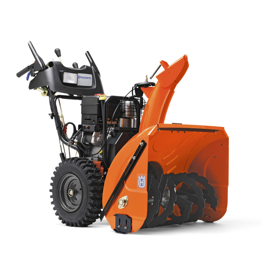
- Page 1 12524SB 12524SB Operator's Manual / 96193004600 / 2009-06...
- Page 2 Safe Operation Practices for Walk-Behind Snow Throwers This snow thrower is capable of amputating hands and feet and throwing objects. Failure to observe the following safety instructions could result in serious injury. Look for this symbol to point out im- por tant safety precautions.
-
Page 3: Table Of Contents
6. When cleaning, repairing or inspecting the snow thrower, stop the engine and make certain the collector/impel- ler and all moving parts have stopped. Disconnect the spark plug wire and keep the wire away from the plug to prevent someone from accidentally starting the engine. -
Page 4: Assembly / Pre-Operation
PARTS PACKED SEPARATELY IN CARTON (1) DISCHARGE CHUTE ROTATOR HEAD MOUNTING (1) WASHER 3/8 (19131316) (6) SHEAR BOLTS 1/4-20 x 1-3/4 ASSEMBLY / PRE-OPERATION Read these instructions and this manual in its entirety before you attempt to assemble or operate your new snow thrower. - Page 5 ASSEMBLY / PRE-OPERATION HOW TO SET UP YOUR SNOW THROWER TOOL BOX (See Fig. 10) A toolbox is provided on your snow thrower. The toolbox is located on top of the belt cover. Store the extra shear bolts, nuts and multi-wrench provided in parts bag in the toolbox. NOTE: The multi-wrench may be used for assembly of the chute rotator head to snow thrower and making ad just ments to the skid plates.
- Page 6 ASSEMBLY / PRE-OPERATION INSTALL AUGER CONTROL ROD (See Figs. 5 and 6) The auger control rod has the short loop on the end of the spring as shown. 1. Slide rubber sleeve up rod and hook end of spring into control arm with loop opening up as shown.
-
Page 7: Operation
OPERATION KNOW YOUR SNOW THROWER READ THIS OWNER'S MANUAL AND ALL SAFETY RULES BEFORE OPERATING YOUR SNOW THROWER. Compare the illustrations with your snow thrower to familiarize yourself with the location of various controls and adjustments. Save this manual for future reference. These symbols may appear on your snow thrower or in literature supplied with the product. - Page 8 MUF FLER GAS O LINE FILLER CAP CHOKE CON- TROL SAFETY IGNITION ON / OFF SWITCH PRIM ER FUEL SHUT-OFF VALVE RECOIL (AUXILIARY) STARTER HANDLE NOTE: ITEMS ABOVE ARE SHOWN IN THEIR TYPICAL LOCATION ON THE ENGINE. ACTUAL LOCATION MAY VARY WITH THE ENGINE ON YOUR UNIT.
- Page 9 The operation of any snow thrower can result in foreign objects thrown into the eyes, which can result in severe eye damage. Always wear safety glasses or eye shields while operating your snow thrower or performing any ad just - ments or repairs.
- Page 10 TO THROW SNOW (See Fig. 13) The auger rotation is controlled by the auger control lever located on the right side handle. • Squeeze auger control lever to handle to engage the auger and throw snow. • Release the auger control lever to stop throwing snow. AUGER CONTROL LEVER...
-
Page 11: Before Starting The Engine
• If snow thrower must be operated over gravel surface, use extra caution and be sure skid plates are adjusted to lowest (highest scraper clear ance) position. 1. Shut off engine and wait for all moving parts to stop. 2. Adjust skid plates by loosening the hex nuts, then mov- ing skid plate to desired position. -
Page 12: Snow Throwing Tips
Allow the engine to warm up for a few minutes. Engine will not develop full power until it has reached normal operat- ing temperature. WARM START - ELECTRIC STARTER Follow the steps above, keeping the choke control in the “OFF” position. COLD START - RECOIL STARTER 1. -
Page 13: Maintenance
GENERAL REC OM MEN DA TIONS The warranty on this snow thrower does not cover items that have been sub ject ed to operator abuse or negligence. To receive full value from the warranty, operator must maintain snow thrower as in struct ed in this manual. Some ad just ments will need to be made periodically to properly maintain your snow thrower. - Page 14 V-BELTS Check V-belts for deterioration and wear after every 50 hours of operation and replace if necessary. The belts are not ad just able. Replace belts if they begin to slip from wear. (See “TO REMOVE BELT COVER” in the Service and Adjustments section of this manual).
-
Page 15: Service And Adjustments
SERVICE AND ADJUSTMENTS WARNING: To avoid serious injury, before performing any service or ad just ments: 1. Be sure the on/off switch is in the OFF position. 2. Remove safety ignition key. 3. Make sure the augers and all mov ing parts have completely stopped. -
Page 16: To Replace Belts
SERVICE AND ADJUSTMENTS TO REPLACE BELTS (See Fig. 20) The auger and traction drive belts are not adjustable. If the belts are damaged or begin to slip from wear, they should be replaced. It is recommended that the belt(s) be replaced by a Sears service center/department. - Page 17 SERVICE AND ADJUSTMENTS TO REMOVE WHEELS (See Fig. 21) • Remove the klik pin and remove wheel from axle. IMPORTANT: When installing wheel, be sure to use the in- nermost hole in axle and the wheel hub hole. To dis en gage drive system from the wheels (for pushing or trans port ing the snow thrower), remove klik pin from wheel hub and insert pin into the outermost hole in axle only.
-
Page 18: Storage
Immediately prepare your snow thrower for storage at the end of the season or if the unit will not be used for 30 days or more. WARNING: Never store the snow thrower with gaso line in the tank in side a build ing where fumes may reach an open flame, spark or pilot light as on a fur nace, water heater, clothes dryer or... -
Page 19: Troubleshooting
TROUBLESHOOTING See appropriate section in manual unless directed to an authorized service center/department. PROBLEM CAUSE Does not start 1. Fuel shut-off valve (if so equipped) in OFF position. 2. Safety ignition key is not inserted. 3. Out of fuel. 4. ON/OFF switch is OFF. 5. - Page 20 532 42 85-35 06.17.09 CL Printed in the U.S.A.