Kenwood TK-860G Service Manual
Uhf fm transceiver
Hide thumbs
Also See for TK-860G:
- Service manual (67 pages) ,
- Service manual supplement (36 pages) ,
- Instruction manual (77 pages)
Table of Contents
Advertisement
UHF FM TRANSCEIVER
TK-860G/862G
SERVICE MANUAL
REVISED
TK-860G (K)
TK-862G (K)
Please use this manual in place of the service manual (preliminary version), B51-8498-00.
We have added the information on the circuit description, specifications, and K3 version specifications to the service
manual (preliminary version), B51-8498-00.
Microphone
(T91-0597-15)
Cabinet (Upper)
(A01-2165-13)
Panel assy
(A62-0642-03)
Microphone
(T91-0597-15)
Cabinet (Upper)
(A01-2165-13)
Panel assy
(A62-0731-03)
© 2000-1 PRINTED IN JAPAN
B51-8498-10 ( N ) 1268
Key top
(K29-5343-02)
Key top
(K29-5344-02)
Advertisement
Table of Contents

Related Manuals for Kenwood TK-860G


Summary of Contents for Kenwood TK-860G
- Page 1 UHF FM TRANSCEIVER TK-860G/862G SERVICE MANUAL REVISED © 2000-1 PRINTED IN JAPAN B51-8498-10 ( N ) 1268 TK-860G (K) Microphone (T91-0597-15) Cabinet (Upper) (A01-2165-13) Panel assy (A62-0642-03) Key top (K29-5343-02) TK-862G (K) Microphone (T91-0597-15) Cabinet (Upper) (A01-2165-13) Panel assy (A62-0731-03)
-
Page 2: Table Of Contents
PERSONNEL SAFETY PC BOARD VIEWS The following precautions are recommended for person- DISPLAY UNIT (X54-3270-10) : TK-860G ..54 nel safety : • DO NOT transmit if someone is within two feet (0.6 DISPLAY UNIT (X54-3280-10) : TK-862G ..55 meter) of the antenna. -
Page 3: General
Your KENWOOD dealer can help you select an antenna sys- tem that will best serve your particular needs. 3-2. Testing 5-2. -
Page 4: System Set-Up
Are you using the external speaker? External speaker (Option) See page 20. See page 21. KCT-19 KCT-18 Are you using ignition sense cable? Accessory connector cable Ignition sense cable (Option) (Option) : You can install either KCT-19 or KCT-20 to the Delivery TK-860G/862G transceiver... -
Page 5: Operating Features
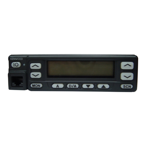
Insert the microphone plug into this connector. Displays the selected channel MON, A, D/A, , and SCN keys (TK-860G) MON, , , and A keys (TK-862G) number. These are PF (Programmable Function) keys. Press each key to activate its auxiliary function. - Page 6 TK-860G/862G OPERATING FEATURES 1-5. Rear panel 2. Operation Features The TK-860G/862G is a UHF FM radio designed to oper- ate in conventional format. The programmable features are summarized. Power input connector 3. Transceiver Controls and Indicators 3-1. Front Panel Controls...
- Page 7 TK-860G/862G OPERATING FEATURES • Display character (TK-860G only) • Public address This key switches the LCD display between the group Public address amplifies the microphone audio, and out- and channel number and the group and channel name. puts it through a PA speaker. PA is activated by pressing this key.
- Page 8 TK-860G/862G OPERATING FEATURES SCAN start condition 3) Selected channel The transceiver reverts to the channel before scanning or One or more non-priority channels must be added to all the channel that you changed during scan. channels that can be scanned. The transceiver must be in 4) Last called channel normal receive mode (PTT off).
-
Page 9: Audible User Feedback Tones
OST (Operator Selectable Tone) Dead Beat Disable (TK-860G K market models only) If the D.B.D. code matches, a predetermined action will The transceiver is capable to have "OST" function and 16 occur. Whether option signalling is activated or not, when tone pair (QT/DQT). -
Page 10: Realignment
= Pre alert tone sounding time). You can select yes or Self programming mode [A]+Power ON (Two seconds) no for the optional feature's warning tone. 3. For the Panel Test Mode (TK-860G only) Setting method refer to ADJUSTMENT. 3-1. For the Panel Tunning Mode Setting method refer to ADJUSTMENT. - Page 11 • The data stored in the personal computer must match 6-3. Programming model type when it is written into the flash memory. • Change the TK-860G/862G to PC mode, then attach the 1. Start up the programming software (KPG-56D), select interface cable.
-
Page 12: Clone Mode
The operation is as follows (the transmit radio is the master and the receive radio is the slave). 1. Turn the master TK-860G power ON with the [ ] key Cloning cable held down. The TK-860G displays "CLONE". - Page 13 DQT 000~777 DQT000I* Note : (Inverse) DQT777I* If the radio type of TK-860G was temporally set to "Por- (1 step mode) table" for the cloning purposes, "UNPROG" is displayed (at User mode) when the TK-860G is turned on. DQT 023~754 DQT023I_ In this case, please set the radio type back to "Mobile"...
- Page 14 TK-860G/862G REALIGNMENT No. Function Choices Display Remarks No. Function Choices Display Remarks PWR_H___ ←Default Step STP__250 Display when an item High power frequency 2.5kHz~1MHz STP_1000 is selected or when a power Low power PWR_L___ step is changed 10 Wide/ Wide WIDE____ (about 0.5 seconds)
- Page 15 Remarks Option signalling [D/A]/[ ] Function key [MON] Data clear [MON] Not function MON__OFF [D/A]/[ ] [MON] (TK-860G Volume down MON___1_ Busy channel lockout [D/A]/[ ] only) Volume up MON___2_ [MON] Beat shift yes/no Talk around MON___3_ [D/A]/[ ] [MON]...
- Page 16 KEY3__24 TK-862G cannot be selected ←Default [D/A] No function KEY2_OFF Group up KEY3__25 TK-862G cannot be selected ←Default (TK-860G) Volume down KEY2__1_ No function KEY4_OFF Volume up KEY2__2_ (TK-860G) Volume down KEY4__1_ (TK-862G) Talk around KEY2__3_ Volume up KEY4__2_ Auxiliary...
- Page 17 TK-860G/862G REALIGNMENT No. Function Choices Display Remarks No. Function Choices Display Remarks Public address SCN___12 Public address CUP___12 Horn alert SCN___14 Horn alert CUP___14 Selectable QT SCN___15 M destination only Selectable QT CUP___15 M destination only 2-tone encode SCN___16 TK-862G cannot be selected...
- Page 18 TK-860G/862G REALIGNMENT No. Function Choices Display Remarks No. Function Choices Display Remarks Key lock VUP___10 15 Minimum 0~31/1 step MVOL_12_ Public address VUP___12 volume Horn alert VUP___14 16 Off hook Enable H_D__ENA ←Default Selectable QT VUP___15 M destination only decode Disable...
- Page 19 Others PTM__ENA ←Default 47 Panel Enable test/ Not used for TK-862G 11. Memory Reset Mode (TK-860G only) panel Disable PTM__DIS You can clear all settings you made in self programming tuning mode, or you can return to the original display.
-
Page 20: Installation
TK-860G/862G INSTALLATION 1-2. KCT-19 Accessory Port Function 1. Accessory Connection Cable Name Function Note (KCT-19 : Option) (A) (B,C,D,E) The KCT-19 is an accessory connection cable for con- Serial control data input necting external equipment. The connector has 15 pins and Data channel control/ the necessary signal lines are selected for use. - Page 21 TK-860G/862G INSTALLATION 2. Accessory Terminal (TX-RX Unit) 3. Ignition Sense Cable (KCT-18 : Option) 2-1. External Connector Accessory Terminal Method The KCT-18 is an optional cable for enabling the ignition function. The ignition function lets you turn the power to the...
- Page 22 5. Fitting the Control Panel Upside Down on/off Disable Disable ← Power cannot The TK-860G/862G control panel can be fitted upside down, so the transceiver can be mounted with its internal be turned on speaker (in the upper half of the case) facing down in your...
- Page 23 TK-860G/862G INSTALLATION 2. Fold the flat cable ( ) in the opposite direction ( 6. External Speaker 3. Rotate the control section ( ) 180 degrees ( 6-1. KES-3 : Option 4. Insert the flat cable into the control section connector, The KES-3 is an external speaker for the 3.5-mm-diam-...
-
Page 24: Circuit Description
TK-860G/862G CIRCUIT DESCRIPTION IF Amplifier Frequency Configuration The first IF signal is amplified by Q13, and the enters IC5 The receiver utilizes double conversion. The first IF is (FM processing IC). The signal is heterodyned again with a 49.95MHz and the second IF is 450kHz. The first local oscil- second local oscillator signal within IC5 to create a 450kHz lator signal is supplied from the PLL circuit. - Page 25 (J1) output. Fig. 6) CONTORL UNIT IC508 IC507 IC13 The TK-860G/862G has VCO in a Sub-unit (A1) housed in AUDIO a solid shielded case and connected to the TX-RX unit AF PA PROCE. CONV. through CN101.
- Page 26 TK-860G/862G CIRCUIT DESCRIPTION PLL/VCO IC3 : PLL IC Q103 TX VCO RF AMP 5kHz/6.25kHz Q106 BUFF D102,104 Phase Charge Q101 comparator pump DATA RX VCO Q102, 104,105 T/R SW 5kHz/6.25kHz D101,103 16.8MHz Fig. 6 PLL circuit Unlock Circuit Transmitter System...
- Page 27 5) Controls the PLL (IC3). Key Matrix Circuit 6) Controls the D/A converter (IC6) and adjusts the volume, The TK-860G/862G front panel has function keys. Each modulation and transmission power. of them is connected to a cross point of a matrix of the KIN0 to KOUT2 ports of the microprocessor.
- Page 28 TK-860G/862G CIRCUIT DESCRIPTION Encode D/A Converter The QT and DQT signals are output from TO of the CPU The D/A converter (IC6) is used to adjust TONE and MO (IC502) and summed with the external pin DI line by the...
-
Page 29: Semiconductor Data
TK-860G/862G SEMICONDUCTOR DATA Microprocessor : 30622M4102GP (TX-RX Unit IC502) Terminal function Pin No. Name Function Pin No. Name Function EMGT External MIC control. Mobile MIC : H Pull up. DTMF DTMF/2TONE/BEEP output. – 2TONE decode pulse input. HOLD Not used. - Page 30 TK-860G/862G SEMICONDUCTOR DATA Shift Register : BU4094BCFV LCD Driver : LC75833W Terminal function (TX-RX unit IC510) (Display Unit IC801 : TK-862G only) Pin No. Port Name Function Block diagram Wide/Narrow SW. Narrow : H MUTE MIC mute (M models only). Mute : H MIC/LCD backlight control.
-
Page 31: Description Of Components
D503 Reverse current KOUT 2 prevention D504 Reverse current KOUT 0 TX-RX Unit (X57-5960-XX) prevention -10 : TK-860G K,M -11 : TK-862G K -14 : TK-860G K3 D505 Reverse current KOUT 1 Ref. No. Use/Function Operation/Condition prevention Surge absorption D506... - Page 32 TK-860G/862G DESCRIPTION OF COMPONENTS Ref. No. Use/Function Operation/Condition Ref. No. Use/Function Operation/Condition DC switch Active while PS voltage is more DC amplifier PC/TV control than 20V Shift/Store register HNC, 8RC, 8TC, SPMUTE, RX, PA/LI, AUX5, AUX6 RF amplifier DC switch...
-
Page 33: Parts List
TK-860G/862G PARTS LIST CAPACITORS CC 45 TH 1H 220 J • Capacitor value Color* CC45 010 = 1pF 0 = 22pF 100 = 10pF 1 = Type … ceramic, electrolytic, etc. 4 = Voltage rating Multiplier 101 = 100pF 2 = Shape … round, square, ect. -
Page 34: Display Unit (X54-3270-10) : Tk-860G
Les articles non mentionnes dans le Parts No. ne sont pas fournis. Y : AAFES (Europe) X: Australia M: Other Areas Teile ohne Parts No. werden nicht geliefert. TK-860G/862G DISPLAY UNIT (X54-3270-10) : TK-860G, DISPLAY UNIT (X54-3280-10) : TK-862G Desti- Desti- Ref. No. Address Parts No. - Page 35 Description parts nation parts nation CK73GB1H471K CHIP C 470PF TX-RX UNIT (X57-5960-XX) CC73GCH1H020B CHIP C 2.0PF -10 : TK-860G K,M -11 : TK-862G K -14 : TK-860G K3 CK73GB1H471K CHIP C 470PF D509-514 B30-2050-05 C92-0555-05 CHIP-TAN 0.047UF 35WV D521 B30-2151-05...
- Page 36 TK-860G/862G PARTS LIST TX-RX UNIT (X57-5960-XX) Desti- Desti- Ref. No. Address Parts No. Description Ref. No. Address Parts No. Description parts nation parts nation C155 CC73GCH1H060D CHIP C 6.0PF C227 C93-0558-05 CHIP C 8.0PF C156 CK73GB1H471K CHIP C 470PF C227...
- Page 37 TK-860G/862G PARTS LIST TX-RX UNIT (X57-5960-XX) Desti- Desti- Ref. No. Address Parts No. Description Ref. No. Address Parts No. Description parts nation parts nation C554 CK73GB1H122K CHIP C 1200PF E40-3247-05 PIN ASSY C555 C92-0566-05 CHIP-TAN 10UF 6.3WV E40-3246-05 PIN ASSY...
- Page 38 TK-860G/862G PARTS LIST TX-RX UNIT (X57-5960-XX) Desti- Desti- Ref. No. Address Parts No. Description Ref. No. Address Parts No. Description parts nation parts nation CP539 R90-0724-05 MULTI-COMP 1K X4 R92-1252-05 CHIP R 0 OHM R92-1252-05 CHIP R 0 OHM RK73GB1J223J...
- Page 39 TK-860G/862G PARTS LIST TX-RX UNIT (X57-5960-XX) Desti- Desti- Ref. No. Address Parts No. Description Ref. No. Address Parts No. Description parts nation parts nation R145,146 RK73GB1J473J CHIP R 1/16W R509,510 R92-1252-05 CHIP R 0 OHM R147 RK73GB1J683J CHIP R 1/16W...
- Page 40 TK-860G/862G PARTS LIST TX-RX UNIT (X57-5960-XX) Desti- Desti- Ref. No. Address Parts No. Description Ref. No. Address Parts No. Description parts nation parts nation R578 RN73GH1J682D CHIP R 6.8K 1/16W MA4PH633 DIODE R579 RK73GB1J223J CHIP R 1/16W 1SV280 VARIABLE CAPACITANCE DIODE...
- Page 41 TK-860G/862G PARTS LIST TX-RX UNIT (X57-5960-XX) PLL/VCO (X58-4670-XX) Desti- Desti- Ref. No. Address Parts No. Description Ref. No. Address Parts No. Description parts nation parts nation DTC114EKA DIGITAL TRANSISTOR TC106 C05-0384-05 CERAMIC TRIMMER CAP (10P/8) DTA114EKA DIGITAL TRANSISTOR TC109 C05-0384-05...
- Page 42 TK-860G/862G EXPLODED VIEW (TK-860G) Parts with the exploded numbers larger than 700 are not supplied.
- Page 43 TK-860G/862G EXPLODED VIEW (TK-862G) Parts with the exploded numbers larger than 700 are not supplied.
- Page 44 TK-860G/862G PACKING 45 Microphone 13 DC cord (T91-0597-15) : K,K3 33 Protection bag (E30-3339-05) (H25-0720-04) 19 Fuse (10A) (F51-0016-05) x 2 5 Cap (B09-0235-05) 38 Bracket (J29-0627-23) 32 Inner packing case (H12-1391-03) 36 Holder (J19-1584-05) 42 Screw set (N99-0395-05) 31 Polystyrene foamed fixture (R)
- Page 45 TK-860G/862G ADJUSTMENT • Signalling Test Mode (TK-860G Only) Signalling No. Test Mode Operating Features None None This transceiver has a test mode. To enter test mode, None 100Hz square press [SCN] key and turn power on. Hold [SCN] key un- QT 67.0Hz...
- Page 46 TK-860G/862G ADJUSTMENT Tuning Mode Display Function name FREQ_ _XX Frequency adj. HPOW_XXX H.POW_XXX H.P.OW_XXX H.P.O.W_XXX H.P.O.W._XXX H.P.O.W._.XXX RF high power Hi power (L) Hi power (L') Hi power (C) Hi power (H') Hi power (H) [D/A] [D/A] [D/A] [D/A] [D/A] LPOW_XXX L.POW_XXX...
- Page 47 TK-860G/862G ADJUSTMENT Test Equipment Required for Alignment Test Equipment Major Specifications 1. Standard Signal Generator Frequency Range 400 to 520MHz (SSG) Modulation Frequency modulation and external modulation Output –127dBm/0.1µV to greater than –7dBm/100mV 2. Power Meter Input Impedance 50Ω Operation Frequency...
-
Page 48: Pll/Vco (X58-4670-Xx)
TK-860G/862G ADJUSTMENT Adjustment Location Adjustment Point Switch (TK-860G) Volume Channel Power up/down Display up/down TX-RX UNIT (A/2) MIC jack Programmable function keys TC106 Note PLL/VCO • Flash memory RSSI TC109 The firmware program (User mode, Test mode, Tuning IC5 9pin mode, etc.) and the data programmed by the FPU (KPG-56D) - Page 49 TK-860G/862G ADJUSTMENT Common Section Since the TK-862G cannot be tuned from the panel, the FPU (KPG-56D) should be used for adjustment. Measurement Adjustment Item Condition Specifications/Remarks Test- Unit Terminal Unit Parts Method equipment ± 0.1V 1. PLL lock 1) Set test mode TX-RX CV TC106 7.5V K,M...
- Page 50 TK-860G/862G ADJUSTMENT Measurement Adjustment Item Condition Specifications/Remarks Test- Unit Terminal Unit Parts Method equipment 3. Squelch 3 1) Set test mode Rear Front CH / Adjust to the • Wide Select “SQL3” in tuning mode. panel panel squelch threshold “S.QL3”...
- Page 51 TK-860G/862G ADJUSTMENT Measurement Adjustment Item Condition Specifications/Remarks Test- Unit Terminal Unit Parts Method equipment 6. QT check 1) Set test mode Rear CH : CH1 - Sig4 panel SSG MOD AF VTVM INT : 3kHz (Wide), 1.5kHz (Narrow) Distortion (EXT.SP) EXT : 151.4Hz...
- Page 52 TK-860G/862G ADJUSTMENT Measurement Adjustment Item Condition Specifications/Remarks Test- Unit Terminal Unit Parts Method equipment ± 0.5W 3) “L.P.O.W” Power mete Rear Front CH / 5.0W PTT : ON panel panel Adjust [ *** ] 4) “L.P.O.W.” PTT : ON Adjust [ *** ] 5) “L.P.O.W._.”...
- Page 53 TK-860G/862G ADJUSTMENT Measurement Adjustment Item Condition Specifications/Remarks Test- Unit Terminal Unit Parts Method equipment ± 3kHz± 0.2kHz (Wide) 8. MIC 1) Set test mode Power meter Rear Check ± 1.5kHz± 0.05kHz (Narrow) seisitivity CH : CH1 - Sig1 Deviation panel...
- Page 54 TK-860G/862G TK-860G/862G PC BOARD VIEWS DISPLAY UNIT (X54-3270-10) : TK-860G DISPLAY UNIT (X54-3270-10) : TK-860G Component side view Foil side view C806 C806 C807 C807 R808 R808 R809 R809 CN801 CN801 C801 C801 R801 R801 C802 C802 C805 C803 C805...
- Page 55 TK-860G/862G PC BOARD VIEWS DISPLAY UNIT (X54-3280-10) : TK-862G DISPLAY UNIT (X54-3280-10) : TK-862G PLL/VCO (X58-4670-XX) -12 : K,M -14 : K3 Component side view Component side view Foil side view J72-0676-02 C115 C119 L109 CN101 L103 C104 L112 (ST) 6...
- Page 56 TK-860G/862G PC BOARD VIEW TX-RX UNIT (X57-5960-XX) (A/2) Component side view -10 : TK-860G K,M -11 : TK-862G K -14 : TK-860G K3 Ref. No. Address Ref. No. Address Ref. No. Address Ref. No. Address IC13 IC400 Component side IC400...
- Page 57 Ref. No. Address Ref. No. Address Ref. No. Address Ref. No. Address Ref. No. Address Ref. No. Address -10 : TK-860G K,M -11 : TK-862G K -14 : TK-860G K3 D16 11N Q18 13N D18 12Q IC10 Component side IC400...
-
Page 58: Tx-Rx Unit (X57-5960-Xx) (A/2)
Ref. No. Address Ref. No. Address Ref. No. Address Ref. No. Address Ref. No. Address Ref. No. Address -10 : TK-860G K,M -11 : TK-862G K -14 : TK-860G K3 IC13 Component side view + Foil side IC14 IC15 Q10 13M... - Page 59 TK-860G/862G PC BOARD VIEWS TX-RX UNIT (X57-5960-XX) (B/2) -10 : TK-860G K,M -11 : TK-862G K -14 : TK-860G K3 Component side view D512 J72-0678-02 B/2 D511 R566 C543 R567 R559 R560 L501 C501 C542 R618 R561 IC510 R619 IC507...
- Page 60 TK-860G/862G PC BOARD VIEW TX-RX UNIT (X57-5960-XX) (B/2) -10 : TK-860G K,M -11 : TK-862G K -14 : TK-860G K3 Component side view + Foil side J72-0678-02 B/2 D512 D511 R550 R501 R548 C533 R553 C534 R566 R559 C543 L501...
- Page 61 TK-860G SCHEMATIC DIAGRAM Note : Components marked with a dot (·) are parts of patterun 1.
-
Page 62: Schematic Diagram
TK-862G SCHEMATIC DIAGRAM Note : Components marked with a dot (·) are parts of patterun 1. -
Page 63: Block Diagram
TK-860G/862G TK-860G/862G TK-860G/862G BLOCK DIAGRAM... -
Page 64: Level Diagram
TK-860G/862G TK-860G/862G LEVEL DIAGRAM Receiver Section Center Frequency 49.95MHz 450kHz Audio Frequency To make measurements in the RF section, connect the RF level meter. In the RF section, use a 0.01µF coupling capacitor. (The display shows the SSG input value required to obtain 12dB SINAD.) -
Page 65: Terminal Function
TK-860G/862G TERMINAL FUNCTION CN1 (TX-RX Unit) CN3 (TX-RX Unit) Pin No. Name Function Pin No. Name Function DC 8V output. Horn alert/call output. DC 5V output. Ground. AUX5 SMRD : Reset output. *1 Switched B+, DC 13.6V output, Maximum 1A. -
Page 66: Specifications
K3 : 400 to 430MHz Number of Channels ......TK-862G : Maximum 8 channels TK-860G : Maximum 128 channels Number of Groups ......TK-860G : Maximum 128 groups Channel Spacing ......... Wide : 25kHz Narrow : 12.5kHz PLL Channel Stepping ......5, 6.25kHz Operating Voltage ....... - Page 67 Mechelsesteenweg 418 B-1930 Zaventem, Belgium KENWOOD ELECTRONICS FRANCE S.A. 13, Boulevard Ney, 75018 Paris, France KENWOOD ELECTRONICS U.K. LIMITED KENWOOD House, Dwight Road, Watford, Herts., WD1 8EB United Kingdom KENWOOD ELECTRONICS EUROPE B.V. Amsterdamseweg 37, 1422 AC Uithoorn, The Netherlands KENWOOD ELECTRONICS ITALIA S.p.A.