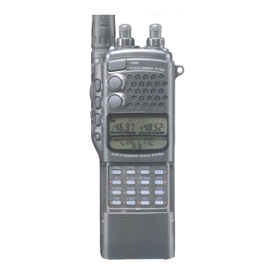
Kenwood TH-78A Instruction Manual
144/440mhz fm handheld dual bander
Hide thumbs
Also See for TH-78A:
- Service manual (114 pages) ,
- Instruction manual (72 pages) ,
- Instructions (4 pages)
Table of Contents
Advertisement
Quick Links
Advertisement
Table of Contents

Related Manuals for Kenwood TH-78A


Summary of Contents for Kenwood TH-78A
- Page 1 KENWOOD TH-78A 144/440MHz FM Handheld Dual Bander Instruction Manual...
-
Page 2: Table Of Contents
KENWOOD TH-78A 144/440 MHz Dual Bander INSTRUCTION MANUAL CONTENTS CONTROLS OVERVIEW ..........................THE BATTERY PACK 1 NiCd Battery Pack (PB-13) ......................... 2 Recharging ..............................3 Installing The Battery Pack ......................... 4 Battery Voltage Level ..........................5 Battery Operating Time .......................... - Page 3 9 CALL/VFO Scan ............................10 CALL/Memory Scan ............................ 11 VFO/Memory/CALL Scan ........................... 12 The Alert function ............................REPEATER OPERATION 1 Transmitter Offsets ............................. 2 Selecting the Offset Direction ........................3 Automatic Offset Selection ......................... 4 Manual Offset Selection ..........................5 The REVerse Function ..........................6 Tone Selection ............................
- Page 4 11 MHz Mode ..............................12 Channelized Frequency Display ........................POWER SAVER FEATURES 1 The Battery Saver Mode ..........................2 Automatic Power Off (APO) ......................... CLOCK FUNCTION 1 Timer Setting ............................... 2 Timer Function ............................DUPLEX OPERATION ..........................POWER ON MESSAGE AND FUNCTION 1 Power On Message ............................
-
Page 5: Controls Overview
CONTROLS OVERVIEW Page 5... -
Page 6: The Battery Pack
THE BATTERY PACK NiCd Battery Pack (PB-13) You must charge the battery pack before you can use it. It has not been charged at the factory in order to provide you with the greatest number of charge/discharge cycles. It takes several charge/discharge cycles before the battery pack will operate for its maximum period. -
Page 7: Battery Operating Time
Manganese or Alkaline batteries Fully charge Fully discharged Approximate battery condition Battery Operating Time (hours) 144 MHz 430/440 MHz Batteries Alkaline Manganese PB-13 PB-17 PB-18 • 6 seconds transmit, 6 seconds receive, 48 seconds reception with no signal recommended. AF output 0.2W/8 ohms. •... -
Page 8: Tuning Control And Volume Control
Tuning Control and Volume Control This transceiver assigns two volume and tuning control functions to the two controls on the top of the radio. Before proceeding to the next step, master these functions. The default setting is as follows: Functions as the Functions as the volume control for tuning control of... - Page 9 Separate VOLUME control function Press the F key then press the E.CHG key. Functions as the Functions as the volume control for volume control of the VHF band. The UHF band. The inside knob of the LEFT control functions as the VOLUME control for the VHF band, and the inside knob of the RIGHT control functions as the VOLUME control for the UHF band.
-
Page 10: Selecting Frequency
VHF band. UHF band. 1) Rotate the SQL control fully counter clockwise. 2) Rotate the VOL control clockwise until a signal or noise is heard coming from the speaker. 3) Rotate the SQL clockwise until the noice just disappears and the BUSY indicator turns off. This point is known as the Squelch Threshold point. -
Page 11: Step Size Selection
5) The transceiver actually changes frequency only after the 1 kHz digit is entered. The 1 kHz digit is not displayed if it is a zero. If you do not enter the 1 kHz digit, the 1 kHz indicator flashes and the transceiver defaults to the previous operating frequency. -
Page 12: Programmable Vfo Tuning Limits
10!20!12.5!25!10 UHF BAND 3) Press any key except the POWER, LAMP, and MONI keys. The displayed step size is set, and the normal frequency display returns. Changes in the Displayed Frequency As you change from one step size to another, the displayed frequency also changes, as illustrated in the accompanying charts. -
Page 13: Basic Receiving Functions
3) Select the desired upper tuning limit. For example, you might want to select the 145 MHz band and dial up 145.100 MHz. 4) Press and hold the M key for longer than one second, then press the 2 key. This selects the upper frequency limit for the programmable VFO. -
Page 14: Changing Transmitter Output Power
Changing Transmitter Output Power Press the F key, then the D/LOW key to select three different transmitter power output levels. Repeat this function to step through the power level selections. The actual transmitter output power for this unit depends upon the power supply used. -
Page 15: Using The Memory
The time-out-timer function cannot be turned on or off. USING THE MEMORY Microprocessor Memory Backup All memory channel data is backed up in EEPROM. It is not lost unless you reset the memory. All other data that you set is retained by a secondary lithium battery that will provide memory backup for about 20 days if you remove the battery pack or external DC power. -
Page 16: Memory Contents
Memory Contents Each memory channel can store information as shown in the chart below. X = Can be stored in memory Normal Split Channel Channel RF frequency TX frequency Tone (CCSS) frequency Tone (CTCSS) status Frequency step Shift statue, REV on/off DTSS code, DTSS status Entering Memory Data Entering memory data is a simple operation requiring just a few keystrokes to store all the data you require. -
Page 17: Entering The Call Channel Frequencies
3) Use the keypad to select any desired memory channel number (0-49). For example, use a two digit number, such as 02 for channel 2, or 15 for cannel 15, to enter data in memory. 4) Press the MR key. 5) The memory channel number will turn off, indicating that the receiver data has been properly stored. -
Page 18: Recalling Memory Channels
Recalling Memory Channels Press the MR key. You can change the memory channel by the following two methods. Using the Tuning Control Rotate the tuning control clockwise or counterclockwise to select the desired Memory Channel. Using the numeric keypad Select any desired memory channel number (0-49). For example, use a two digit number, such as 02 for channel 2, or 15 for cannel 15. -
Page 19: Scanning
3) Press the M key, then press the f key to enter the message setting mode. APO 11 4) Enter your message with the keypad. See the list on page 37 for the key combinations for each letter. 5) If you enter the wrong message, press the VFO key to start over step 4. 6) Press the MR key at the end. -
Page 20: Scan Operation Cancel
In combined CTCSS and DTSS modes, scanning stops when the proper CTCSS tone is received. Squelch will open only if the DTSS signal matches when the scan stops. The transceiver is delivered from the factory in the Time Operated Scan mode. Scan operation cancel Operation band: Press any key except the MONI, LAMP, BAND, MHz, E.CHG, or MSG. -
Page 21: Scanning Memory Channels
Scanning Memory Channels Note The transceiver scans only those memory channels that have data entered and are not locked out. Scanning does not start unless two channels or more have data entered 1) Adjust the SQL control to the threshold point. 2) Press the MR key. -
Page 22: Mhz Scan
For example, you can program so that the transceiver scans a range from 144.50 to 145.80 in the VHF band. Use the following procedure to specify the desired scan limit. 1) Press the band key to select the desired Band. 2) Select the desired upper scan limit. -
Page 23: Vfo/Memory Scan
VFO / Memory Scan This function lets you alternately scan the VFO frequency shown on the display and the last-used memory channel. 1) Adjust the SQL control to the threshold point. 2) Press the F key, then press the MR key. 3) The VFO frequency and the last used memory channel are scanned alternately. -
Page 24: Repeater Operation
- to simplex where no indicator shows. In the European version (UHF band), - change to - -. Automatic Offset Selection The TH-78A is programmed according to the standard ARRL (American Radio Relay League) Band Plan for repeater offset direction. You can override this programming by using the SHIFT key as described in the preceding paragraph. -
Page 25: Tone Selection
For example, repeater A uses 146.000 as an input frequency, and 146.600 as an output frequency. Repeater B might use 146.600 as an input frequency, and 146.000 as an output frequency. It would be quite inconvenient to have to reprogram the transceiver each time you want to use these repeaters. Press the F key, then press the SHIFT/REV key. -
Page 26: Autopatch Operations
Tone Function Operation Press the TONE key. A "T" indicator appears on the display, and the transmitter sends the desired tone when you press the PTT switch. Autopatch Operations (U.S.A. versions only) Some repeaters offer a service called autopatch. This feature allows you to dial a telephone number from your transceiver and carry on a telephone conversation. -
Page 27: Dtmf Memory
3) Release the 2 key. You are now able to enter numbers without pressing and holding the PTT switch. Repeat 1 and 3 to cancel the delay time. DTMF Memory You can store 10 DTMF telephone numbers up to a maximum of 15 digits long in memory. Storing DTMF Codes 1) Press the M key, then press the MHz key to select the DTMF code entry mode. -
Page 28: Operation As A Repeater
3) The DTMF code appears on the display. Note Transmission continues until the whole code string is recalled, even if the PTT switch is released. You cannot stop DTMF code transmission once it is initiated. OPERATION AS A REPEATER This transceiver is capable of operating as a repeater. The transceiver listens on both bands simultaneously. As soon as a signal is received on one band, the other shifts from receive to transmit and re-transmits the incoming signal. -
Page 29: The Dual Tone Squelch System (Dtss)
The desired band will now operate in the Tone Squelch mode. That is, squelch will not open until the selected tone is received as a portion of the incoming signal. If you want to set the CTCSS function to another band, repeat steps 1 and 2. Note In duplex operation, if CTCSS is activated in the Sub and Main bands it is not active during transmission. -
Page 30: Using Dtss With A Repeater
5) To transmit, press the PTT switch. The DTSS code is sent for about 0.5 second. Note Voice output is muted during code output. We recommend that you turn off the battery saver function when you use DTSS. 6) Press the F key, then press the 2 key to cancel the DTSS function. Note Although you can select the CTCSS function simultaneously in both band, an incoming DTSS... -
Page 31: Paging Code Memory
Unlike DTSS, the calling station code displays on the transceiver so the receiving party can identify the calling station. If called with an individual code, the individual caller code displays. When called with a group code, the group code displays. Paging Operation Overview Set your station code Tune to frequency of the other station... - Page 32 3) Rotate the tuning control to select A (your individual code channel). 4) Enter your individual code (000 to 999) using the numeric keys. 5) Your station ID is set in memory A. 6) Select 1 to 6 with the tuning control. 7) Enter the next Paging Code Memory you wish to program as described in step 4.
-
Page 33: Sending Pages (Calling)
Sending Pages (Calling) 1) Turn to the predetermined frequency. 2) Press the F key then press the 1 key to enter the Paging mode. The Paging function of the other transceiver must also be on. 3) Press and hold the F key for longer than one second, then press the 1 key to enter the code setting mode. 4) Use the tuning control to select the memory channel where the local station code is stored Calling All Group Members Select the group code memory channel to call all members of a group. -
Page 34: Receiving Pages (Wait)
4) You can cancel Paging once you have established contact. Local station code 444 and your station ID code ill are transmitted. The DTMF sounds as the codes are transmitted. Receiving Pages (Wait) 1) Tune to the predetermined frequency. 2) Press the F key then press the 1 key to enter the Paging mode. Receiving a Page with an Individual Code 1) When the proper code is received, your squelch will open and you will hear an alert tone sequence coming from the speaker. -
Page 35: Canceling Signal Squelch
3) Press the PTT switch to respond to the calling party. Note An E indicator appears on the display if the local station cannot be recognized. Note You can communicate more efficiently if you cancel Paging after contacting the local station. Canceling Signal Squelch Squelch will not open when operating in the paging mode when the paging codes do not match. -
Page 36: Message Transmission And Reception
MESSAGE TRANSMISSION AND RECEPTION This function lets you transmit your message to the other party or display a message from the other party on your transceiver using the DTMF (Dual Tone Multi Frequency) signal and alphanumeric display. You can use the numerics 0 to 9 and letters A to Z. The message that can be transmitted and received at one time can be up to six characters long. -
Page 37: Message Memory Check
Relationship between input characters and keys (Note: "+" means press two keys in sequence [within 2 seconds]) Input Input Input Input characters operation characters operation characters operation characters operation 1 + A (F) 1 + B (M) (space) 1 + C (f 2 + A (F) 2 + B (M) 2 + C (f... -
Page 38: Receive Message Memory
2) The MESSAGE display lights, and you can now receive a message. When a message is received, it is displayed, and the MESSAGE indicator flashes. • DTSS mode • Paging mode Press any key Receive Message Memory This transceiver has 10 incoming message memory channels, in which received messages are stored. If you press the MESSAGE key in the message mode, the last stored message is displayed. -
Page 39: The Tone Alert System
Press and hold the M key for longer than one second, then press the MESSAGE key. Note This operation does not clear the transmit message memory that you set. ENHANCED RECEIVED FUNCTIONS The Tone Alert System The Tone Alert function provides an audible alarm to indicate when someone is transmitting on the frequency you are monitoring. -
Page 40: Monitor
Monitor Even if the squelch or CTCSS, DTSS, or PAGING is ON, you can monitor the channel by pressing the MONI key. Beep Off The transceiver produces beeps when you push the front panel keys. If you want to disable this function, press and hold the 6 key and press the POWER switch. -
Page 41: Switching Speaker Output When A Speaker-Microphone Is Connected
3) Connect your earphone to the External Speaker jack. 4) Set the volume to a comfortable level. Note If you perform this operation, the internal speaker volume is also reduced. If you stop using the earphone, repeat step 1 to return to the original volume settings. -
Page 42: 10. Single Band Operation
• To simultaneously receive two VHF band signals 1) Press the BAND key to select the UHF band. 2) Press the f key. The UHF band display also shows the second VHF band frequency. • To simultaneously receive two UHF band signals 1) Press the BAND key to select the VHF band. -
Page 43: Power Saver Features
1) Turn the POWER switch off 2) Press and hold down the 3 key, then press the POWER switch. Channel numbers are displayed on both bands. 3) The channel number can be changes with the tuning control. 4) To return to normal frequency display, preform steps 1 & 2 again. POWER SAVER FEATURES 1) The Battery Saver Mode This transceiver provides a battery saver mode to conserve on battery power. -
Page 44: Clock Function
CLOCK FUNCTION If you press the F key, then the 7 key in receive mode, the clock is displayed on the Sub band display. The time is displayed on a 24-hour basis. If you press the F key, then the 7 key again, the clock is canceled, and the normal frequency display returns. -
Page 45: Duplex Operation
With the Tuning control, set the "Hour" display to the time you want the transceiver to turn off. Press the M key. With the Tuning control, set the "Minute" display to the time you want the transceiver to turn off. Press the F key. -
Page 46: Power On Message And Function
In this mode, the microphone sensitivity and receive audio are reduced automatically to prevent howling. The transmitter output power is also automatically set to the position. You can select the desired transmitter output power by pressing the F key, then pressing the D/LOW key. To cancel this function, repeat the procedure for setting the function. - Page 47 DTMF2S Setting DTMF signal transmission delay time (2 seconds) Earphone mode MSG M1 Store receive messages in up to 10 memory channels. MSG MX If more than 10 messages are received, the oldest messages are replaced with the new ones. MSGCLR Message transmission memory clear OPG OFF...
-
Page 48: Troubleshooting
TROUBLESHOOTING He following problems are generally caused by improper transceiver operation or connection, not by defective components. If you experience any of these problem, check the causes and corrective actions before requesting service. Symptom Probably Cause Corrective Action Indicators do not light and no 1. -
Page 49: Installing The Ctcss Unit (Tsu-7)
1. Installing the CTCSS Unit (TSU-7) Slide the battery release button to unlock, then pull out the battery case. Unscrew the four screws on the rear (Fig. 1). The screw nearest the antenna is a short one. Put your finger into the battery holder, and release the claw of the rear case. (Fig. 2) Position the set with its front facing forward. -
Page 50: Memory Expansion Unit (Me-1)
2. Memory Expansion Unit (ME-1) Slide the battery release button to unlock, then pull out the battery case. Unscrew the four screws on the rear (Fig. 1). The screw nearest the antenna is a short one. Put your finger into the battery holder, and release the claw of the rear case. (Fig. 2) Position the set with its front facing forward. -
Page 51: Programming The Smc-33 Remote Control Speaker Microphone
To reset the function of the transceiver leys. Connect the SMC-33 to the MIC jack on top of the transceiver. Press and hold Microphone key 1 (or 2 or 3) and turn the power on. The programmable function (PF) indicator appears for 10 seconds. -
Page 52: Using Other Microphones
Using Other Microphones If not using the Kenwood SMC-33 microphone (made for this radio), we recommend using an electret type microphone. The input impedance is 2K ohms and the DC voltage on the microphone terminal is approximately 4 volts (Max. 3.5mA). Do not use a dynamic microphone.