Table of Contents
Advertisement
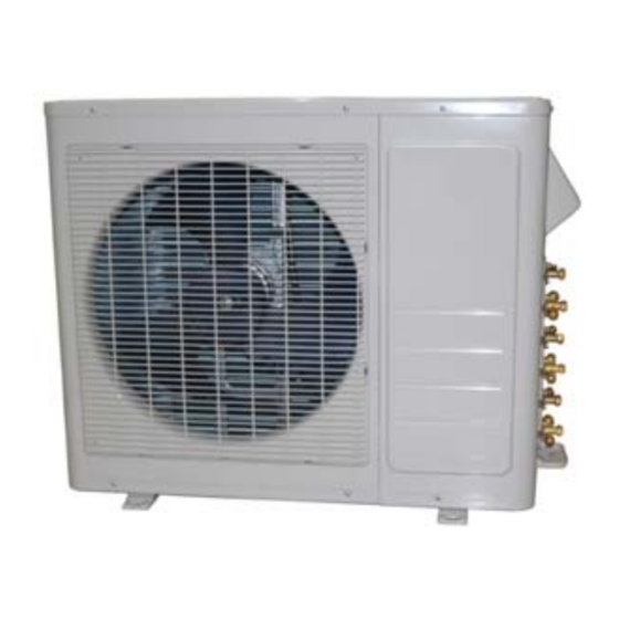
CONDENSING UNITS
Revision B: ODMI‐C1‐1310
Model Numbers:
YN018GMFI16M2D (Dual)
YN027GMFI16M3D (Trio)
Table of Contents
1.
2.
3.
4.
5.
6.
7.
8.
Wiring Diagrams And Electrical Trouble Shooting
9.
WARNING
Installation MUST conform with local building codes or, in the absence of local
codes, with the National Electrical Code NFPA70/ANSI C1-1993 or current edition
and Canadian Electrical Code Part1 CSA C.22.1.
The information contained in the manual is intended for use by a qualified service
technician familiar with safety procedures and equipped with the proper tools and
test instruments
Installation or repairs made by unqualified persons can result in hazards to you
and others.
Failure to carefully read and follow all instructions in this manual can result in
equipment malfunction, property damage, personal injury and/or death.
YN-M SERIES MULTI SPLIT SYSTEM
MULTI CIRCUIT OUTDOOR UNITS
(2, 3 AND 4 ZONES) SERVICE MANUAL
2014 AND NEWER MODELS (50130070 AND
NEWER Serials)
YN030GMFI16M3D (Trio)
Yn036Gmfi16M4D (Quad)
Parker Davis HVAC International, Inc.
2260 NW 102nd Place, Doral, FL 33172
Ph: (305) 513-4488 info@pd-hvac.com
Advertisement
Table of Contents
Troubleshooting

Related Manuals for Pioneer YN018GMFI16M2D


Summary of Contents for Pioneer YN018GMFI16M2D
- Page 1 NEWER Serials) CONDENSING UNITS Parker Davis HVAC International, Inc. 2260 NW 102nd Place, Doral, FL 33172 Revision B: ODMI‐C1‐1310 Ph: (305) 513-4488 info@pd-hvac.com Model Numbers: YN018GMFI16M2D (Dual) YN030GMFI16M3D (Trio) YN027GMFI16M3D (Trio) YN036GMFI16M4D (Quad) Table of Contents Product Specifications Indoor Unit Combination Suggested Indoor Unit Model Numbers...
-
Page 2: Table Of Contents
9.4 Diagnosis and Solution ............................... 38 9.5 Trouble Criterion Of Main Parts............................82 Disassembly Instructions ..............................93 Model: YN018GMFI16M2D (Dual Split) .......................... 93 Model: YN027GMFI16M3D (Triple Split) ........................100 Model: YN030GMFI16M3D (Triple Split) ........................107 Model: YN036GMFI16M4D (Quad Split) ........................115... -
Page 3: Product Specifications
Product Specifications Model YN018GMFI16M2D YN027GMFI16M3D YN030GMFI16M3D YN036GMFI16M4D Power supply Ph-V-Hz 230V~ 60Hz, 1Ph 230V~ 60Hz, 1Ph 230V~ 60Hz, 1Ph 230V~ 60Hz, 1Ph MINIMUM CIRCUIT AMPACITY 11.0 18.0 18.0 27.0 MAX.FUSE 15.0 30.0 30.0 40.0 ---- Starting current ---- ---- ----- Model... -
Page 4: Indoor Unit Combination
1. Indoor Unit Combination Multi DC Nominal Suggested Multi DC Nominal Suggested Limit Limit Outdoor Unit capacity Combination Outdoor Unit capacity Combination DUAL ZONE 5.2kW None (18K Nominal) 9+12 12+12(*) 9+12 9+18 12+12 Multi DC Nominal Suggested Limit Outdoor Unit capacity Combination 12+18... -
Page 5: Suggested Indoor Unit Model Numbers
2. Suggested Indoor Unit Model Numbers SUGGESTED INDOOR UNIT WB009GMFI16MLD WB012GMFI16MLD CB012GLFI16MLD RB012GMFI16MLD UB012GMFI16MLD FB012CMFI16MLD SUGGESTED INDOOR UNIT WB009GMFI16MLD WB012GMFI16MLD CB012GLFI16MLD RB012GMFI16MLD UB012GMFI16MLD FB012CMFI16MLD WB018GMFI16MLD CB018GLFI16MLD RB018GMFI16MLD UB018GMFI16MLD SUGGESTED INDOOR UNIT WB009GMFI16MLD WB012GMFI16MLD CB012GLFI16MLD RB012GMFI16MLD UB012GMFI16MLD FB012CMFI16MLD WB018GMFI16MLD CB018GLFI16MLD RB018GMFI16MLD UB018GMFI16MLD SUGGESTED INDOOR UNIT WB009GMFI16MLD... - Page 6 3. Dimensions Of the Outdoor Units: Dimension mm (In.) Model YN018GMFI16M2D 845 (33.3) 320 (12.6) 700 (27.6) 908 (35.7) 560 (22) 335 (13.2) YN027GMFI16M3D YN030GMFI16M3D 900 (35.4) 315 (12.4) 860 (33.9) 980 (38.6) 590 (23.2) 333 (13.1) YN036GMFI16M4D 990 (39) 345 (13.6)
-
Page 7: Refrigerant Cycle Diagram
4. Refrigerant Cycle Diagram 5.1Refrigeration circuit drawing of inverter dual zone (2 zones) INDOOR OUTDOOR EXV A CAPILIARY A LIQUID VALVE A CHECK VALVE EXV B CAPILIARY B LIQUID VALVE B Condenser temp. sensor CAPILIARY TUBE HEAT HEAT EXCHANGE T4 Ambient T1 Room EXCHANGE (EVAPORATOR) -
Page 8: Installation Details
5. Installation Details ● When refrigerant pipe diameter is different 6.1 Wrench torque sheet for installation from that of outdoor unit union (for 12K and 18K indoor units), additional brass adapter Additional tightening Outside diameter Torque torque union (supplied) needs to be used on outdoor unit union to change the size. - Page 9 1. Evacuation using a vacuum pump 2. Air purging by refrigerant Procedure: 1). Confirm that both the 2-way and 3-way 1. Completely tighten the flare nuts of the indoor service valves are set to the closed and outdoor units, confirm that both the 2-way position.
-
Page 10: Adding The Refrigerant After Running The System For Many Years
3. Adding refrigerant if the pipe length 6.5 Adding the refrigerant after running exceeds length for factory pre-charge pipe the system for many years length value. (Recommended only if the refrigerant being added does not exceed 10% of the total refrigerant amount. Otherwise, remove the remaining refrigerant entirely and recharge fully). -
Page 11: Re-Installation While The Indoor Unit Need To Be Repaired
6.6 Re-installation while the indoor unit 2. Air purging by the refrigerant needs to be repaired 1. Collecting the refrigerant into the outdoor unit. Procedure: 1). Confirm that both the 2-way and 3-way valve cores are set to fully closed position. Procedure 2). -
Page 12: Re-Installation While The Outdoor Unit Need To Be Repaired
at the bottom of the cylinder. If the refrigerant is R410A, set the cylinder upside down to ensure 6.7 Re-installation while the outdoor unit liquid charge. needs to be repaired 2). Purge the air from the charging hose. 1. Evacuating the entire system Open the valve at the bottom of the cylinder and press the check valve on the charge set to purge the air (be careful of the liquid refrigerant). -
Page 13: Electronic Function
6. Electronic Function 7.3.4 Inverter module Protection. ----Inverter module protection has protection 7.1 Abbreviation functions against current, voltage and T1: Indoor ambient temperature temperature. If these protections are triggered, the corresponding code will display on indoor unit T2: Coil temperature of indoor heat exchanger's LED and A/C will stop. - Page 14 Heating mode: RET_OIL_TIME2_ADD and then resume back to former frequency. Current Current limit Frequency limit 2.During the oil return process, the EXV will stay frequency(Hz) value(A) at 300p setting while the indoor units will keep the HEAT_F16 IHEATLMT12 Decrease the frequency to HEAT_F4 and run at HEAT_F4 for current running mode.
-
Page 15: Control And Functions
7.4 Control and Functions According to the final capacity request to confirm the operating frequency, as per the 7.4.1 Capacity Request Calculation following table. Total capacity Request=Σ(Norm code × HP) /10× … COOL modify rate+ correction Frequency (Hz) L_F1 L_F1 L_F2 …... - Page 16 Plus all the indoor capacity requests together, When T2> T2_ExitT4LowFre_ADD-2 and T4>-6, then modify it by T4 the highest frequency can’t exceed F17 When there is only one indoor unit When T2> T2_ExitT4LowFre_ADD-4 and T4>-8, the highest frequency can’t exceed F18 Outdoor temperature (T4) When T2>...
-
Page 17: Outdoor Fan Control
1 minute High When low ambient cooling is valid: 7.4.3.2 Heating mode For YN027GMFI16M3D: High low ambient cooling For YN018GMFI16M2D, YN030GMFI16M3D and For YN018GMFI16M2D, YN030GMFI16M3D and YN036GMFI16M4D: YN036GMFI16M4D: DC_FAN_SSLOW_SPD_ADD 21℃ DC_FAN_HI_SPD_ADD 28℃ 19℃ 26℃... - Page 18 7.4.4 Electronic Expansion Valve (EXV) 7.4.4.2 Heating mode Control The initial open angle of EXV is 250P, adjustment 1.EXV will be fully closed when the power is first range is 100-350p.. When the unit starts to work turned on. Then EXV will stay at standby with for 3minutes, the outdoor will receive indoor units' 350P open and will open to target angle after (of capacity demand) T2 information and...
-
Page 19: Wiring Diagrams
7. Wiring Diagrams 8.1 Wiring diagram of DUAL Circuit outdoor unit YN018GMFI16M2D... - Page 20 PCB board of YN018GMFI16M2D...
- Page 21 IPM board of YN018GMFI16M2D...
- Page 22 8.2 Wiring diagram of Triple Circuit outdoor unit YN027GMFI16M3D YN030GMF16M3D...
- Page 23 PCB board of YN030GMFI16M3D...
- Page 24 IPM board of YN030GMFI16M3D...
- Page 25 PCB board of YN027GMFI16M3D...
- Page 26 IPM board of YN027GMFI16M3D...
- Page 27 8.3 Wiring diagram of Quadruple (4) zone outdoor unit YN036GMFI16M4D...
- Page 28 PCB board of YN036GMFI16M4D...
- Page 29 IPM board of YN036GMFI16M4D...
- Page 30 PFC board of YN036GMFI16M4D...
-
Page 31: Troubleshooting
8. Troubleshooting 9.1Safety Because there are capacitors on the PCBs and relative circuitry in outdoor units, even after shutting down the power supply, electrical power remain charged in those capacitors. Do not forget to discharge the electrical power remaining in the capacitors before servicing. The value of resistance used for discharging the power should be about 1500 ohms to 2000 ohms Electrolytic Capacitors (HIGH VOLTAGE! CAUTION!) - Page 32 8.2 Indoor Unit Error Display WB series Wall Mount Indoor Units: ODU Error code Display Failure Indoor EEPROM malfunction —— Communication malfunction between indoor and outdoor units E2 Zero-crossing signal error —— Indoor fan speed has been out of control —— Open circuit or short circuit of outdoor temperature sensor or outdoor EEPROM malfunction E0,E4 ...
- Page 33 For CB Series Ceiling Cassette, RB Series Ceiling Concealed (Ducted) and UB Series Floor- Ceiling (Flex Mount) Indoor Units: ODU Error Operatio Display Timer De-frost Alarm Failure code Open or short circuit of T1 temperature sensor —— ★ Open or short circuit of T2 temperature sensor ——...
- Page 34 9.3 Outdoor Unit Display 9.3.1 Outdoor unit error code function There is a system check switch on the outdoor PCB. Push the switch SW1 to check the status of unit when the unit is running. The digital display will display the codes based on the following procedures, after pushing the SW1 each time.
- Page 35 A Indoor unit capacity demand code B Indoor unit capacity demand code Norm code*HP C Indoor unit capacity demand code (9K:1HP,12K:1.2HP,18K:1.5HP) D Indoor unit capacity demand code E Indoor unit capacity demand code Outdoor unit amendatory capacity demand code Forced cooling:7 The frequency corresponding to the total indoor units amendatory capacity demand The frequency after the frequency limit...
- Page 36 Average value of T2 (Sum T2 value of all indoor units)/( number of indoor units in good connection) Outdoor unit fan motor state Off:0, High speed:1, Med speed:2, Low speed:3 Breeze:4, Super breeze:5 The last error or protection code 00 means no malfunction and protection 9.3.2 Outdoor unit’s digital display digits: There is a digital display on outdoor PCB.
- Page 37 9.3.3 Outdoor unit error display IDU Display LED STATUS Error Error (Others) (Wall Mt.) E5 E6 Outdoor EEPROM malfunction E1 E2 Communication malfunction between indoor and outdoor units —— —— Communication malfunction between IPM board and outdoor main board E5 E6 ...
-
Page 38: Diagnosis And Solution
9.4 Diagnosis and Solution 9.4.1 Indoor unit trouble shooting 9.4.1.1 Indoor EEPROM malfunction diagnosis and solution. Malfunction decision PCB main chip does not receive feedback from EEPROM chip conditions ● Installation mistake ● PCB faulty Trouble shooting: Supposed causes EEPROM: a read‐only memory whose contents can be erased and reprogrammed using a pulsed voltage. For the location of EEPROM chip, please refer to the below photos. ... - Page 39 Trouble shooting: Indoor / outdoor units communication error Start: Power off , then Power on the A/C by the Breaker. (reconnect the power wire). Is it still displaying the error code? Check wiring on the outdoor and indoor terminal follow the wiring diagram. Is all Reconnect the wiring connecting correctly? Reconnect the wiring Measure Vs, is it moving alternately between positive value Is all the wiring between Turn on all indoor unit by remote and negative value? (Vs is the terminal and Indoor PCB controller. Is all indoor unit display voltage between S and L2). Refer connect ok? PIC 1 Change the Indoor PCB Turn off the all indoor units. Is IPM power LED or operating LED lamp change IPM On? Refer PIC2 Power on by remote controller, I Is it still displaying the error code after 3 minutes? ” Is the reactor connecting Is main board“ Reconnect the wiring lamp on? Refer PIC 3. well?...
- Page 40 Pic 1:Use a multimeter to test the DC voltage between L2 port and S port of outdoor unit. The red pin of multimeter connects with L2 port while the black pin is for S port. When AC is normal running, the voltage will move alternately between positive value and negative value.
- Page 41 PIC3 :Main board LED when power on and unit standby. PIC 4: Check point button, press 1 time for check how many indoor units are connected.( YN027GMFI16M3D) Check point button, press 18 times for check how many indoor units are connected.(for Others) 9.4.1.3 zero-crossing signal error diagnosis and solution. Malfunction decision When PCB does not receive zero crossing signal feedback for conditions 4 minutes or the zero crossing signal time interval is abnormal. Supposed causes ●...
- Page 42 9.4.1.4 Indoor fan speed has been out of control diagnosis and solution. Malfunction decision When indoor fan speed stays too low (300RPM) for certain time, the unit conditions will stop and the LED will display the failure. Supposed causes ● Wiring mistake ●...
- Page 43 Index 1: 1.Indoor AC fan motor Measure the resistance value of each winding by using the tester. For the definite value of the resistance, refer to 9.5 Trouble Criterion Of Main Parts 2. Indoor DC fan motor (control chip is inside fan motor) Measure the resistance value of each winding by using the tester.
- Page 44 Index2: 1: Indoor AC fan motor Power on and set the unit running in fan mode at high fan speed. After running for 15 seconds, measure the voltage of pin1 and pin2. If the value of the voltage is less than 100V (208~240V power supply) or 50V (115V power supply), the PCB must have problems and need to be replaced.
- Page 45 DC motor voltage input and output For Cassette, Ducted, Floor-Ceiling (except console): Color Signal Voltage Vs/Vm 192V~380V Black White 13.5-16.5V Yellow 0~6.5V Blue For console: Color Signal Voltage 310V White Blue Yellow 0-7.5V Black 9.4.1.5 open or short circuit of temperature sensor diagnosis and solution. Malfunction decision If the sampling voltage is lower than 0.06V or higher than conditions...
-
Page 47: Trouble Shooting
9.4.1.6 IPM module or IGBT over-strong current protection diagnosis and solution. Malfunction decision When the voltage signal that IPM send to compressor drive conditions chip is abnormal, the display LED will show “P6” and AC will turn off. Supposed causes ●... - Page 48 9.4.1.7 Over voltage or too low voltage protection diagnosis and solution.
- Page 49 9.4.1.8 Temperature protection of compressor top diagnosis and solution. If the sampling voltage is not 5V, the LED will display the Malfunction decision conditions failure. Supposed causes ● Wiring mistake ● Over load protector faulty ● System block ● Outdoor PCB faulty Temperature protection of compressor top Whether compressor...
- Page 50 Full-Water malfunction (For cassette/A5 duct) 9.4.1.10 diagnosis and solution Malfunction decision If the sampling voltage is not 5V, the LED will display the conditions failure. Supposed causes ● Wiring mistake ● Water-level switch faulty ● Water pump faulty ● Indoor PCB faulty...
- Page 51 9.4.1.11 Mode conflict. Error Code Malfunction decision The indoor units cannot work cooling mode and heating at same time. conditions Heating mode has a priority. Unit action ● Suppose Indoor unit A working in cooling mode or fan mode, and indoor unit B is set to heating mode, then A will change to off and B will work in heating mode.
- Page 52 9.4.2 Outdoor unit trouble shooting 9.4.2.1 E0(Outdoor EEPROM malfunction) error diagnosis and solution Error Code Malfunction decision PCB main chip does not receive feedback from EEPROM chip conditions Supposed causes ● Installation mistake ● PCB faulty Trouble shooting: EEPROM: a read-only memory whose contents can be erased and reprogrammed using a pulsed voltage. For the location of EEPROM chip, please refer to the below photos.
- Page 53 9.4.2.2 E2(Communication malfunction between indoor and outdoor units error diagnosis and solution. Error Code Malfunction decision Indoor unit does not receive the feedback from outdoor unit conditions during 120 seconds or outdoor unit does not receive the feedback from any one indoor unit during 180 seconds. Supposed causes ●...
- Page 54 Pic 1:Use a multimeter to test the DC voltage between L2 port and S port of outdoor unit. The red pin of multimeter connects with L2 port while the black pin is for S port. When AC is normal running, the voltage will move alternately between positive value and negative value.
- Page 55 Pic 2: :IPM (For quad-zone) Power, Self‐Check Operating PIC3 :Main board LED when power on and unit standby. PIC 4: Check point button, press 1 time for check how many indoor units are connected. ...
- Page 56 9.4.2.3 E3(Communication malfunction between IPM board and outdoor main board) error diagnosis and . Error Code Malfunction decision PCB main chip does not receive feedback from IPM module conditions during 60 seconds. Supposed causes ● Wiring mistake ● PCB faulty Trouble shooting:...
- Page 57 Remark: Use a multimeter to test the DC voltage between black pin and white pin of signal wire The normal value should be around 5V. Use a multimeter to test the DC voltage between black pin and red pin of signal wire. The normal value should be around 12V.
- Page 58 9.4.2.4E4(open or short circuit of outdoor temperature sensor) diagnosis and solution F1/F2/F3/F4/F5 (open or short circuit of indoor coil temperature sensor) diagnosis and solution. Error Code E4/F1/F2/F3/F4/F5 Malfunction decision If the sampling voltage is lower than 0.06V or higher than conditions 4.94V, the LED will display the failure.
- Page 59 9.4.2.5 E5 (Voltage protection) error diagnosis and solution. Error Code Malfunction decision An abnormal voltage rise or drop is detected by checking the conditions specified voltage detection circuit. Supposed causes ● Power supply problems. ● System leakage or block ● PCB faulty Trouble shooting:...
- Page 60 IPM (for dual/tri- zone) IPM (for quad- zone) P-N (for dual/tri-zone)
- Page 61 P-N (for quad-zone)
- Page 62 bridge rectifier (for dual/tri-zone) bridge rectifier (for quad-zone)
- Page 63 Remark: Measure the DC voltage between + and - port. The normal value should be 190V~250V.
- Page 64 9.4.2.6 E6(PFC module protection) error diagnosis and solution. (Only for YN036GMFI16M4D) Error Code Malfunction decision When the voltage signal that PFC sends to main control board conditions is abnormal, the display LED will show “E6” and AC will turn off. Supposed causes ●...
- Page 65 Inductance Two ports of the inductance...
- Page 67 9.4.2.7 E8 (Outdoor fan speed has been out of control) diagnosis and solution (Only for DC fan motor models). Error Code Malfunction decision When outdoor fan speed keeps too low (300RPM) or too high (2400RPM) conditions for certain time, the unit will stop and the LED will display the failure. Supposed causes ●...
- Page 68 Index 1: 1. DC fan motor(control chip is inside fan motor) Measure the resistance value of each winding by using the tester. If any resistance value is zero, the fan motor must have problems and need to be replaced. Color Black White Yellow...
- Page 69 DC motor voltage input and output Color Signal Voltage Vs/Vm 140~380V(M2OC-18HFN1- M&M4OC-36HRFN1-M) 192~380V(M3OC-30HRFN1-M) Black White 13.5~16.5V Yellow 0~6.5V Blue...
-
Page 70: Error Code
9.4.2.8 P0(Temperature protection of compressor top) error diagnosis and solution. (Only for YN027GMFI16M3D) Error Code Malfunction decision If the sampling voltage is not 5V, the LED will display the failure. conditions Supposed causes ● Wiring mistake ● Over load protector faulty ●... - Page 72 9.4.2.9 P1 (High pressure protection) error diagnosis and solution. (Only for YN036GMFI16M4D) Error Code Malfunction decision If the sampling voltage is not 5V, the LED will display the failure. conditions Supposed causes ● Wiring mistake ● Over load protector faulty ●...
- Page 74 9.4.2.10 P2(Low pressure protection) error diagnosis and solution. (Only for YN036GMFI16M4D) Error Code Malfunction decision If the sampling voltage is not 5V, the LED will display the conditions failure. Supposed causes ● Wiring mistake ● Over load protector faulty ● System block ●...
- Page 76 9.4.2.11 P3(Current protection of compressor) error diagnosis and solution. Error Code Malfunction decision If the compressor current exceeds the current limit value for conditions 10 seconds, the LED will display the failure. Supposed causes ● Wiring mistake ● Over load protector faulty ●...
- Page 78 9.4.2.12 P4(Temperature protection of compressor discharge) error diagnosis and solution. Error Code Malfunction decision When the compressor discharge temperature(Tp) is more conditions than 115℃ for 10 seconds, the compressor will stop restart till Tp is less than 90℃. Supposed causes ●...
- Page 79 9.4.2.13 P5 (High temperature protection of condenser) error diagnosis and solution. Error Code Malfunction decision When outdoor pipe temperature is more than 65°C, the unit will stop, and unit runs again when outdoor pipe temperature is less conditions than 52°C Supposed causes ●...
- Page 80 9.4.2.14 P6 (IPM module protection) error diagnosis and solution. Error Code Malfunction decision When the voltage signal that IPM send to compressor drive conditions chip is abnormal, the display LED will show “P6” and AC will turn off. Supposed causes ●...
- Page 81 9.4.2.15 The cooling operation or heating operation does not operate. Supposed causes ● 4-way valve faulty Check of 4-way, please refer to part 5 in 9.5 Trouble Criterion Of Main Parts. 9.4.2.16 When cooling, heat exchanger of non-operating indoor unit frosts. When heating, non-operating indoor unit get warm.
-
Page 82: Trouble Criterion Of Main Parts
WZDK37-38G WZDK37-38G Model 12k Floor-Ceiling 18k Floor-Ceiling Indoor fan motor WZDK55-38GS-W WZDK55-38GS-W Model 12k Floor Console Indoor fan motor RD-280-20-8A Outdoor unit Model YN018GMFI16M2D YN027GMFI16M3D YN030GMFI16M3D YN036GMFI16M4D Compressor DA130S1C-20FZ DA150S1C-20FZ DA250S2C-30MT TNB306FPGMC-L Outdoor fan motor WZDK50-38G YDK53-6FB(B) WZDK72-38G WZDK180-38G ... - Page 83 1.Temperature sensor checking Disconnect the temperature sensor from PCB, measure the resistance value with a tester. Temperature Sensors. Room temp.(T1) sensor, Indoor coil temp.(T2) sensor, Outdoor coil temp.(T3) sensor, Outdoor ambient temp.(T4) sensor, Compressor discharge temp.(Tp) sensor. Measure the resistance value of each winding by using the multi-meter.
- Page 84 Appendix 1 Temperature Sensor Resistance Value Table (℃--K) K Ohm K Ohm K Ohm K Ohm ℃ ℃ ℃ ℃ 115.266 12.6431 2.35774 0.62973 108.146 12.0561 2.27249 0.61148 101.517 11.5000 2.19073 0.59386 96.3423 10.9731 2.11241 0.57683 89.5865 10.4736 2.03732 0.56038 84.2190 10.000 1.96532...
- Page 85 Appendix 2 Unit: ℃ ---K Discharge temp. sensor table 542.7 68.66 13.59 3.702 511.9 65.62 13.11 3.595 62.73 12.65 3.492 455.9 59.98 12.21 3.392 430.5 57.37 11.79 3.296 406.7 54.89 11.38 3.203 384.3 52.53 10.99 3.113 363.3 50.28 10.61 3.025 343.6 48.14 10.25...
- Page 86 Appendix 3: 10 11 12 13 14 15 16 17 18 19 20 21 22 ℃ 48 50 52 54 56 58 60 62 64 66 68 70 72 ℉ 23 24 25 26 27 28 29 30 31 32 33 34 35 ℃...
- Page 87 3.IPM continuity check Turn off the power, let the large capacity electrolytic capacitors discharge completely, and dismount the IPM. Use a digital tester to measure the resistance between P and UVWN; UVW and N. Normal Normal resistance Digital tester Digital tester resistance value value...
-
Page 88: Way Valve
Position Resistance Value YDK53- YDK70-6FB YDK180-8GB YSK27-4G YSK68-4B YDK45-6B YSK25-6L 6FB(B) 56Ω±8% (20 24.5Ω±8% (20 317Ω±8% (20 145Ω±8% (20 345Ω±8% (20 627Ω±8% (20 88.5Ω±8% (20 Black - ℃ ) ℃ ) ℃ ) ℃ ) ℃ ) ℃ ) ℃ ) 76Ω±8% (20 19Ω±8% (20 252Ω±8% (20... - Page 89 6.EXV check Disconnect the connectors.
- Page 90 Red Brown Blue Orange Yellow White Resistance to EXV coil Color of lead wire Normal Value Red- Blue Red - Yellow About 50Ω Brown-Orange Brown-White...
- Page 91 Red- Blue Red - Yellow...
- Page 92 Brown-Orange Brown-White...
-
Page 93: Disassembly Instructions
9. Disassembly Instructions Model: YN018GMFI16M2D Part name Procedures Remarks How to remove the panel plate. Screws of top cover Panel plate 1) Stop operation of the air conditioner and turn “OFF” the power breaker. Screws of front panel 2) Remove the screws of top... - Page 94 Screws of big handle Screws of right- rear panel Screws of water collector Screws of terminal board How to remove the fan ass’y. Fan ass’y 1) Remove the top cover, right front side panel and front panel from item 1.step 1~4 2) Remove the hex nut fixing ②...
- Page 95 4) Remove the electrical ④ control box cover. 5) Disconnect the fan motor connector CN37(5p,white) from the PCB board. ⑤ Remove the fan motor after unfastening four fixing screws. ⑥ How to remove the electrical Electrical ③ parts. parts 1) Perform work of item 1,2. 2) Remove the ten screws fixing the IPM board.
- Page 96 CN38(2p,white) CN21(5p,white) CN39(2p,blue) L-OUT(red) N-OUT(blue) CN17 Remove the IPM board. CN15 Disconnect the connectors and wires connected from PCB and other parts. CN25/CN23 CN18/CN19 Connectors: CN17:T3/T4 temp. sensor (2p/2p,white) CN7: Tdischarge temp. sensor (2p,white) CN15:T2B-A,B temp. sensor (2p/2p,white) CN18/CN19: Electronic expansive CN5/CN6 CN1/CN2 valve A,B (6p/6p,red/red)
- Page 97 (red-red) CN3:L-IN (red) CN4:N-IN (black) ⑧ Disconnect the grounding wire (yellow-green) after removing the big handle and the right-rear panel. Remove the PCB board. How to remove the compressor. Compressor 1) Perform work of item 1,2,3. 2) Remove electrical control box and partition plate.
- Page 98 Reactor How to remove the reactor 1) Perform work of item 1,2 2) Unfasten connector between IPM and reactor. 3) Remove screws cover of inductance, and remove cover inductance Screws of cover of inductance 4) Disconnect two pieces of wires connected from the cover of inductance.
- Page 99 How to remove the expansion expansion valve valve 1) Perform work of item 1,2. 2) Remove the electrical parts from item 3.. Expansion valves 3) Remove the coils. 4) Detach the welded parts of Coils expansion valves and pipes.
- Page 100 Model: YN036GMFI16M3D Part name Procedures Remarks How to remove the panel plate. Panel plate Screws of top cover 1) Stop operation of the air conditioner and turn “OFF” the power breaker. 2) Remove the screws of top cover, and remove the top cover.
- Page 101 Screws of big handle Screws of right-rear panel Screws of water collector Screws of terminal board How to remove the fan ass’y. Fan ass’y 1) Remove the top cover, right front side panel and front panel from item 1.step 1~4 2) Remove the hex nut fixing ②...
- Page 102 ④ 5) Disconnect the fan motor connector CN11(5p,white) from the PCB board. ⑤ 6) Remove the fan motor after unfastening six fixing screws. Note: There are two kinds of screws. Please pay attention to it when install the fan motor. ⑥...
- Page 103 Disconnect following 3 pieces of connection wires and connectors between IPM and PCB. CN21(5p,white) L-OUT(red) N-OUT(blue) Remove the IPM board. ⑥ CN18/CN19/CN22 CN17 Disconnect connectors and wires connected from PCB and other parts. Connectors: CN17:T3/T4 temp. sensor (2p/2p,white) CN7: Tdischarge temp. sensor (2p,white) CN12:Ttop temp.
- Page 104 CN4:L2-IN (black) Disconnect the grounding wire (yellow-green) CN20/ CN23/ after removing the big handle CN25 and the right-rear panel. Remove the PCB board. CN1/CN2 CN5/CN6 ⑧ How to remove the compressor. Compressor 1) Perform work of item 1,2,3. 2) Remove electrical control box and partition plate.
- Page 105 washers fixing compressor to bottom plate. ⑦ 8) Lift the compressor. Reactor How to remove the reactor 1) Perform work of item 1,2 2) Unfasten connector between IPM and reactor. 3) Remove screws cover of inductance, and remove cover inductance Screws of cover of inductance...
- Page 106 How to remove the expansion expansion valve valve 1) Perform work of item 1,2. 2) Remove the electrical parts from item 3. Expansion valves 3) Remove the coils. 4) Detach the welded parts of . Coils expansion valves and pipes.
- Page 107 Model: YN030GMFI16M3D Part name Procedures Remarks How to remove the panel plate. Screws of top cover Panel plate 1) Stop operation of the air conditioner and turn “OFF” the power breaker. 2) Remove the screws of top cover, and remove the top cover.
- Page 108 Screws of top cover Screws of right- rear panel Screws of front panel...
- Page 109 How to remove the fan ass’y. Fan ass’y 1) Remove the top cover, right front side panel and front panel from item 1.step 1~4 2) Remove the hex nut fixing ② the fan. 3) Remove the fan. 4) Remove electrical ④...
- Page 110 Disconnect following 5 ④ pieces of connection wires and connectors between IPM and PCB. L-OUT(red) N-OUT(blue) CN38(2p,white) CN21(5p,white) CN39(2p,blue)
- Page 111 Remove the IPM board. ⑥ 7) Disconnect the connectors and wires connected from PCB and other parts. Connectors: CN17:T3/T4 temp. sensor (2p/2p,white) CN7: Tdischarge temp. sensor CN17 (2p,white) CN15:T2B-A,B,C temp. sensor (2p/2p/2p,white) CN18/CN19/CN22: Electronic expansive valve A,B,C (6p/6p/6p,red/red/red) CN25/CN23/CN20: S-A,S-B,S-C (3p/3p/3p,white/white/white) CN15 CN18/CN19/CN22...
- Page 112 ⑧ How to remove the compressor. Compressor 1) Perform work of item 1,2,3. 2) Remove electrical control box and partition plate. 3) Extract refrigerant gas. 4) Remove sound ⑥ insulation material crankcase heating cable. 5) Remove terminal cover of compressor, and disconnect wires of compressor thermo and compressor from the terminal.
- Page 113 Reactor How to remove the reactor Screws of cover of 1) Perform work of item 1,2 inductance 2) Unfasten the connector between IPM and reactor. 3) Remove four screws cover of inductance, and remove cover inductance 4) Disconnect two pieces of wires connected from the cover of inductance.
- Page 114 How to remove the expansion expansion valve valve 1) Perform work of item 1,2. 2) Remove the electrical parts from item 3. Expansion 3) Remove the coils. valves 4) Detach the welded parts of expansion valves and pipes. . Coils...
- Page 115 Model: YN036GMFI16M4D: Part name Procedures Remarks How to remove the panel plate. Screws of top cover Panel plate 1) Stop operation of the air conditioner and turn “OFF” the power breaker. Screws of front panel Screws of right front side panel 2) Remove the screws of top Screws of top cover cover, and remove the top...
- Page 116 Screws of big handle Screws of right- rear panel Screws of water collector Screws of terminal board...
- Page 117 How to remove the fan ass’y. Fan ass’y 1) Remove the top cover, right front side panel and front panel from item 1.step 1~4 ② 2) Remove the hex nut fixing the fan. 3) Remove the fan. 4) Remove the electrical control box cover after remove 5 screws.
- Page 118 ③ 4) Disconnect following connection wires and connectors on the PFC. C and CN12: (yellow-yellow), connected to PFC inductance. R and CN12: (blue-red), CN12 CN12 ⑤ connected to rectifier. + and - : (red-blue), connected to P1 and P3 on PCB. CN7: (4p,red), connected to CN11 on PCB.
- Page 119 7) Disconnect following connection wires and connectors between PCB and other components. P4: (blue), connected to N on IPM. P2: (red), connected to P on IPM. P1: (red), connected to + on PFC. P3: (blue), connected to – on PFC. RY4: (red), connected to rectifier.
- Page 120 grounding wires of PCB. Remove the PCB board. ⑧ How to remove the compressor. ⑥ Compressor 1) Perform work of item 1,2,3 2) Remove electrical control box and partition plate. 3) Extract refrigerant gas. 4) Remove sound insulation material crankcase heating cable. 5) Remove terminal cover of compressor, and disconnect wires of compressor thermo...
- Page 121 4-way How to remove the 4-way valve valve 1) Perform work of item 1,2. 2) Extract refrigerant gas. 3) Remove the electrical parts Coil from item 3. 4) Remove fixing screw of the Welded parts coil, and remove the coil. 5) Detach the welded parts of 4-way valve and pipe.
-
Page 122: Exploded View
10. Exploded Views: Available under a separate document file. ...