Table of Contents
Advertisement
Advertisement
Table of Contents

Related Manuals for LG GR-P247C


Summary of Contents for LG GR-P247C
- Page 1 REFRIGERATOR SERVICE MANUAL GR-P247C GR-L247C...
-
Page 2: Table Of Contents
Table of Contents Chapter 1 Safety Warning and Cautions ..................3 Chapter 2 Product Standards ......................8 Chapter 3 Circuit Diagram ....................... 9 Chapter 4 Appearance Size of Refrigerator and Name of Every Part ........10 1. Appearance Size of Refrigerator ....................10 2. -
Page 3: Chapter 1 Safety Warning And Cautions
Safety Warning and Cautions Chapter 1 Safety Warning and Cautions ▶ Cautions for safety’ should be observed since they are for previously prevent accidents and dangers when properly use or repair products in a safe manner. ▶ Cautions are classified into ‘Warning’ and ‘Caution’ and meaning of them are as follows Warning Warning means symbol to inform any accidents that may result in large danger such as death or severe injury, etc when violating instructions. -
Page 4: Safety Warnings And Cautions
Safety warnings and cautions Warning If grounding is required, be sure to Do not allow to restore perform grounding. inflammable ether, benzene, alcohol, chemical drugs, LP gas, Be sure to etc in a refrigerator. Grounding nut perform grounding if deemed there is There is danger of Grounding wire danger of electric... - Page 5 Safety warnings and cautions Warning Expand or modify length of power Do not place heavy objects on a plugs to use. refrigerator. Dropping of objects Electric shock or when opening or closing fire may occur doors may injury. due to electrical damage of power cables.
- Page 6 Safety warnings and cautions Caution Do put the vessel that flower base, Do not accumulate objects on a cup, cosmetics or drugs, etc refrigerator or do not keep are contained on the foods in random method. refrigerator. Dropping of objects when opening or closing the door may cause Fire or electric shock may occur, or physical injury.
- Page 7 Safety warnings and cautions Caution power plugs catching with the end Do not use power cords or power of plugs without catching cords. plugs when they are damaged or holes of power plugs are loose. Fire may occur due to electric Fire may occur due to shock or short-circuit.
-
Page 8: Chapter 2 Product Standards
Product Standards Chapter 2 Product Standards Model Name GR-P247C Divison Total inner capacity(L) Effective inner F-Room capacity R-Room Outer dimension (W x D x H) 910 X 788 X 1785 Rated voltage and frequency AC220~240/50~60Hz Product weight (kg) Rated consumption power of motor 90 ±... -
Page 9: Product Standards
Product Standards Chapter 2 Product Standards Model Name GR-L247C Divison Total inner capacity(L) Effective inner F-Room capacity R-Room Outer dimension (W x D x H) 910 X 788 X 1785 Rated voltage and frequency AC220~240/50~60Hz Product weight (kg) Rated consumption power of motor 90 ±... -
Page 10: Chapter 3 Circuit Diagram
Circuit Diagram Chapter 3 Circuit Diagram MODEL : GR-P247C / GR-L247C... -
Page 11: Chapter 4 Appearance Size Of Refrigerator And Name Of Every Part
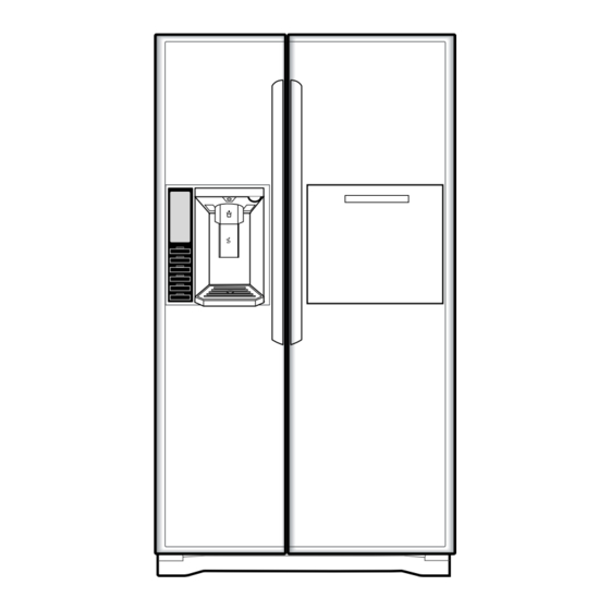
Appearance Size of Refrigerator and Name of Every Part Chapter 4 Appearance Size of Refrigerator and Name of Every Part 1. Appearance Size of Refrigerator (Unit : mm) Model Model GR-P247C / GR-L247C ltem Width(A) Width When opening door by 90°(including handle) (B) 1126... - Page 12 Appearance Size of Refrigerator and Name of Every Part Appearance Size of Refrigerator and Name of Every Part 2. Major Name MODEL : GR-P247C Cover PWB Cover Hinge Oil Product Corner R-Room Shelf Door Ice-maker Mobile Egg Vessel R-Room Basket...
- Page 13 Appearance Size of Refrigerator and Name of Every Part 2. Major Name MODEL : GR-L247C Cover PWB Cover Hinge Oil Product Corner R-Room Shelf Door Ice-maker Mobile Egg Vessel R-Room Basket F-Room Shelf Nano Hardwood Charcoal Deodorization Fresh Vegetable Room Cover Fresh Vegetable Room Vacuum Shielding Type F-Room Drawer...
-
Page 14: Chapter 5 Micom Function
Micom Function Chapter 5 Micom Function 1. Operating panel 1-1. GR-P247C / GR-L247C Dispenser Selection Button Temperature adjustment button for freezer compartment Express freezer button Temperature adjustment button for refrigerator compartment Dispenser light on/off button & filter reset button(3secs) Door open alarm &... - Page 15 2. Function description 2-1. Funnction of Temperature Selection Division Power Initially On 5th Press 6th Press 7th Press 8th Press 9th Press 1st Press 2nd Press 3rd Press 4th Press Change of Type-1 -19 ℃ -15 ℃ -16 ℃ -17 ℃ -18 ℃...
-
Page 16: Automatic Ice Maker
2-2. Automatic ice maker • The automatic ice maker can automatically make 6 pieces of ice cube at a time, 50~60 pieces a day. But these quantities may be varied according to various conditions including how many times the refrigerator door opens and closes. •... - Page 17 2-5. Control of variable type of freezing room fan 1. To increase cooling speed and load response speed, MICOM variably controls freezing room fan motor at the high speed of RPM and standard RPM. 2. MICOM only operates in the input of initial power or special freezing operation or load response operation for the high speed of RPM and operates in the standard RPM in other general operation.
- Page 18 2-10. Function of Trouble Diagnosis(88-LED) 1. Failure diagnosis function is function to facilitate service when nonconforming matters affecting performance of product during use of product. 2. In occurrence of failure, pressing the function adjustment button does not perform function and only alarm sound (“Ding~”) rings.
-
Page 19: Micom Function
Micom Function 2-11. Test Function 1. Test function is function to find out any failed part in the failure status or check function of PWB and the product. 2. The test button is placed on the main PCB (test switch) of the refrigerator. The refrigerator ends the test mode after Max. 2 hours irrespective of modes and returns to normal status (reset). - Page 20 Micom Function 2-12. Functions performed when Ice Dispenser and Water Dispenser are mounted 1. This is function to dispense ice and water outside without opening doors. 2. If pressing the Dispenser Pressing Switch (rubber button) after selecting ice (cube ice, slice ice) or water, relevant ice and water come out.
-
Page 21: Chapter 7 Operation Principle And Repair Method Of Ice Maker & Dispenser
Operation Principle and Repair Method of Ice Maker & Dispenser 2. Function of Ice-maker 2-1. Initial Control Function 1. For the initial power on and when returning to the normal operation after power failure, the ice-maker detects that the ice- maker container is horizontal after MICOM completes initialization, In other words, the detection lever operates up or down. - Page 22 Operation Principle and Repair Method of Ice Maker & Dispenser 2-4. Ice Ejection Control Function 1. This is to eject ice from ice maker cube mould after ice making is completed. 2. If Hall IC signal is on within 3.6 seconds after ice ejection motor rotates in normal direction, it does not proceed ice ejection but waits.
- Page 23 Operation Principle and Repair Method of Ice Maker & Dispenser 2-5. Test Function 1. This function is for forced operation for the purpose of operation test, SVC and cleaning, etc and performed when pressing the test switch mounted on the automatic ice-maker itself for more than 0.5sec. 2.
- Page 24 Operation Principle and Repair Method of Ice Maker & Dispenser 3. Failure Diagnosis Method of Ice Maker * Method to diagnose failure: Failure can be checked when pressing the F-temperature control button and the R- temperature control button for more than a second (if the front LED turns on, it means normal operation): Refer to Failure Diagnosis Function subscribed in Clause 2-10, MICOM Function.
-
Page 25: Chapter 8 Compressor
Heavy Repair Method of Refrigerator by Application of Refrigerant 2. Heavy Repair SVC Method For the heaver repair of R600a type of refrigerator, perform work according to following SVC method. 2-1. Returnof Refrigerator Refrigerant Required equipment: Pinch pliers, refrigerant discharging hose, refrigerant returnbag •... -
Page 26: Heavy Repair Method Of Refrigerator By Application Of Refrigerant
Heavy Repair Method of Refrigerator by Application of Refrigerant 2-2. Returnof Remained Refrigerant Required equipment: Pinch pliers, hose for refrigerant recovery, vacuum pump • If refrigerant returntime of 7 minutes has passed, connect a vacuum pump at the ends of a refrigerant returnhose outdoor. - Page 27 Heavy Repair Method of Refrigerator by Application of Refrigerant 2-4. Charging Tube Connection Step Required equipment: Charging tube, simple welding machine • Remove a charging pipe to recharge R600a refrigerant after completing work, and then connect a charging tube with welding Suction Pipe Charging Tube...
- Page 28 Heavy Repair Method of Refrigerator by Application of Refrigerant 2-6. Refrigerant Charging Required equipment: Bombe, R600a refrigerant (75g) • Firstly remove fire appliances and heating source for performing work when charging scaled refrigerant. (Do not spray refrigerant indoor.) • Measure the accurate quantity (75g) of refrigerant to charge it into a Bombe. •...
- Page 29 Heavy Repair Method of Refrigerator by Application of Refrigerant 2-8. Failure Checking Procedures Check of cooler Check of rotation Surface of at F-Room, R- Normal of COMP cooler is cold. Room Somewhat cold Moisture clogged Leakage of 3way valve Surface of Clogged capillary Clogged cycle cooler is cold.
- Page 30 Heavy Repair Method of Refrigerator by Application of Refrigerant 2-9. Cautions in Heavy Repair Service Special caution should be taken since fire may occur for welding work since refrigerant may remain as it is at the high pressure side even after vacuum air-discharge in relation with cycle clogging. Take power cords out and remove power between 6sec - 12sec after powering on in order to open both sides of 3way valve in the step of refrigerant recovery.
-
Page 31: Troubleshooting
TROUBLESHOOTING 1-3. Troubleshooting With Error Freezer Sensor Error Is it displayed under picture? Disconnect CON7 and Replace measure the value. Is F-sensor resistance value between pins 1 & 2 of CON7 as below? (GY to GY) Pin2 Pin1 Is the connection loose? Reconnect (CON7) Test Point... - Page 32 Refrigerator1 Sensor Error Is it displayed under picture? Replace Disconnect CON8 and R-sensor measure the value. Is resistance value between pins 3 & 4 of CON8 as below? (WH to WH) Is the connection loose? Reconnect (CON8) Pin4 Pin3 Test Point Result 6 ~ 300 ㏀...
- Page 33 Refrigerator2 Sensor Error Is it displayed under picture? Replace Disconnect CON8 and R-sensor measure the value. Is resistance value between pins 5 & 6 of CON8 as below? (GY to GY) Is the connection loose? Reconnect (CON8) Pin5 Pin6 Test Point Result 6 ~ 300 ㏀...
- Page 34 Ambient Sensor Error Is it displayed under picture? Replace Disconnect CON6 and measure the value. Is R-sensor resistance value between pins 7 & 8of CON6 as below? (WH to WH) Is the connection loose? Reconnect (CON6) Pin8 Pin7 Test Point Result 6 ~ 400 ㏀...
- Page 35 Ice maker Sensor Error Is it displayed under picture? Replace Disconnect CON13 and I/Maker measure the value. Is resistance value between pins 1 & 2 of CON13 as below? (GY to GY) Pin1 Pin2 Test Point Result Is the connection loose? Reconnect Pin1 to Pin 2 6 ~ 150 ㏀...
- Page 36 Freezer Defrost Sensor Error Is it displayed under picture? Is resistance value between Replace a pins 1 & 2 of Housing-A as D-Sensor below? (BO to BO) Pin2 Pin1 Is the connection loose? Reconnect (CON7) Test Point Result Pin1 to 1.156 ~ 141.5 ㏀...
- Page 37 Refrigerator Defrost Sensor Error Is it displayed under picture? Is resistance value between Replace a pins 1 & 2 of Housing- A as D-Sensor below? (BO to BO) Pin2 Pin1 Is the connection loose? Reconnect (CON8) Test Point Result Pin1 to 1.156 ~ 141.5 ㏀...
- Page 38 Freezer Defrost Heater Error Replace Is it displayed under picture? Enter the TEST 2 MODE MAIN PCB Is the voltage value between pins 6(BL/WH) and 5 (BN) of CON3 230 V AC? Is the connection loose? Reconnect Pin6 Pin5 Relay operation Test Point Result Pin1 To Pin5...
- Page 39 Replace Is the resistan6e value Is the resistance value of Normal Heaters between pins 6(BL/WH) and heater like as below? 5 (BN)ofCON3 like as below? (1) (2) Heater Resistance Pin6 Pin5 Test Point Result Resistance 230 ~ 260 Ω (1) To (2) Test Point Result 180 ~ 230 Ω...
- Page 40 Refrigerator Defrost Heater Error Replace Is it displayed under picture? Enter the TEST 2 MODE MAIN PCB Is the voltage value between pins 5(BL) and 3 (BN) of CON4 230 V AC? Is the connection loose? Reconnect Pin5 Pin3 Relay operation Test Point Result Pin3 To Pin5...
- Page 41 Replace Is the resistance value Is the resistance value of Normal Heater between pins 5(BL) and heater like as below? 3 (BN) of CON4 like as below? (1) (2) Heater Resistance Pin5 Pin3 Test Point Result Resistance 250 ~ 330 Ω (1) To (2) Test Point Result...
- Page 42 Freezer Fan Error Check fan motor Is it displayed under picture? Does the cold-air come out (Connector, of the top of the main duct? Frozen, Locked) Is the connection loose? Reconnect Replace Is the feedback voltage Main PCB between pin10 and pin11 of CON7 like as below? (from motor to main board) Reset and...
- Page 43 Refrigerator Fan Error Check fan motor Is it displayed under picture? Does the cold-air come out (Connector, of the top of the main duct? Frozen, Locked) Is the connection loose? Reconnect Replace Is the feedback voltage Main PCB betw een pin1 and pin2 of CON12 like as below? (from motor to main board) Replace...
- Page 44 Condenser Fan Error Check fan motor Is it displayed under picture? Is the condenser fan (Connector, rotate? Locked, mouse) Is the connection loose? Reconnect Replace Is the feedback voltage MAIN PCB between pin8and pin9 of CON7 like as below? (from motor to main board) Reset and Replace Enter the TEST 1 MODE...
- Page 45 Communication Error Is it displayed under picture? Is the output voltage Replace between pin3 and pin5 of Display PCB CON101 like as below? Pin5 Pin3 Is the connection loose? Reconnect Display PCB Voltages Test Point Result pin3 To pin5 0 ~ 5 V CON6 Is the connection loose? Reconnect...
- Page 46 Is the connection loose? Is the output voltage Replace Reconnect between Pin4 and pin5 of Main PCB CON6 like as below? CON6 Pin5 Pin4 Trans mi tt er Voltages Is the output voltage betwee Replace Test Point Result n pin4 and pin5 of Main PCB Pin4 To Pin5 0 ~ 5 V...
- Page 47 Water Tank Sensor Error Replace a Is it displayed under picture? Disconnect CON6 and WT-Sensor measure the value. Is resistance value between pins 9& 10of CON6 as below? (GY to GY) Pin10 Pin9 Is the connection loose? Reconnect (CON6) Test Point Result Pin9 to Pin10 6 ~ 300 ㏀...
- Page 48 Ice Maker KIT Error Is it displayed under picture? Inspection Ice Maker Replace module part in freezer room. ICE Maker Unit Is the connection loose? Reconnect (CON13) Ex plain to the customer! Is the voltage between Replace the pins 9 and pin 10 of Main PCB CON13 5V ~ 12V? Pin10...
- Page 49 Crush Mode Does't work Is the connection loose? Replace Is the condition of Reconnect (CON10) Micro Switch the micro switch like as below? Is the connection loose? Reconnect (CON3) Status Teste Normal Infinity 0 Ω Push the Lever...
- Page 50 Replace Replace In Crush Mode, Is the resistance value Main PCB Auger Motor Is the voltage between between (1) and (2) of the pin2 and pin7 of CON4 like Auger motor like as below? as below, while pushing the lever switch? (1) (2) Test Point Result...
- Page 51 Cube Mode Doesn't work Replace Is the connection loose? Is the condition of Reconnect Micro Switch (CON10) the micro switch like as below? Is the connection loose? Reconnect (CON3) Status Teste Normal Infinity 0 Ω Push the Lever...
- Page 52 Replace In Crush Mode, Is the connection loose? Reconnect Main PCB Is the voltage between (Hinge) pin2 and pin7 of CON3 like as below, while pushing the lever switch? Is the connection loose? Reconnect CON4 Pin7 Pin2 Output voltage of auger motor Level switch Test Point Result...
- Page 53 Replace Is the resist ance value Cube between (1) and (2) of the Solenoid Cube solenoi d li ke as below? Resistance of Cube solenoid Level switch Test Point 156.8 ~ 173.3 Ω (1) To (2) After plug in, explain to the customer!
- Page 54 Water Mode Doesn't work Is the connection loose? Is the connection loose? Replace Is the condition of the micro Reconnect Reconnect (CON10) (CON10) Micro Switch switch like as below? (1) PK (2) YL Is the connection loose? Reconnect (CON3) Status Tester Normal Infinity...
- Page 55 In Crush Mode, Is the connection loose? Replace Reconnect Is the voltage between pin2 Main PCB and pin10 of CON3 like as below, while pushing the lever switch? Water Valve Replace Is the resistance value of Pin2 Pin10 CON4 Water-valve Water Valve like as below? Output voltage of Water valve Level switch...
- Page 56 COMP operation error ① ② 1. Open the PWB COVER ③ 2. Check the number of LED blinks When the COMP (Refer to the next page for resolution by number of LED is normal, it will blinks not blink 1. Open the BACK COVER ④...
- Page 57 Resolution by number of LED blinks LED operating condition Cause Service guide 1. After resetting the power check LED blinking 1 time repeatedly PCB part normal operation defect 2. When the same symptom occurs again after taking action for 1, (MICOM) ••Blink -Off-Blink-Off-Blink-Off-Blink-Off-Blink-Off••Repeat replace the PCB...
- Page 58 1. How To Remove Terminal Position Assurance 3. How To Start Test Mode (TPA) Push the TEST button on the Main PWB, You can start the TEST MODE. * AC TPA TEST BUTTON * DC TPA After measure the values, you should put in the TPA again * 1 time * 2 times...
-
Page 59: Exploded View
EXPLODED VIEW FREEZER DOOR PART : GR-P247C / GR-L247C * : Optional part 200A 611B 202A 612A 600A 610A 614A 606A 210C 244A 210B 203A... - Page 60 EXPLODED VIEW DISPENSER PART : GR-P247C / GR-L247C * : Optional part 276A 275A 405A 276B 279A 279I 278B 279H 402C 279J 402C 402C 501D 279B 278D 281B 501A 281A 279C...
- Page 61 EXPLODED VIEW REFRIGERATOR DOOR PART : GR-L247C * : Optional part 241A 241C 230A 241B 232A 212G 240A 147A 240A 240A 242B 244A 233A 242A...
- Page 62 EXPLODED VIEW FREEZER COMPARTMENT : GR-P247C / GR-L247C * : Optional part 625A 616F 616G 270E 627A 101A 271B 271A 607B 135D 120B 270A 607A 402A 404A 135B 130A 619A 120B 620A 135E 135F 120B 128C 302B 128D 135J 128E...
- Page 63 EXPLODED VIEW REFRIGERATOR COMPARTMENT : GR-P247C / GR-L247C * : Optional part 624D 624B 624E 270B 624C 270D 101B 624A 135G 135C 271B 140A 135H 271C 150A 140A 402A 140A 166A 152A 154D 154C 154E 163H 135K 135E 302C 135F...
- Page 64 EXPLODED VIEW MACHINE COMPARTMENT : GR-P247C / GR-L247C * : Optional part 303E 406A 502A 303C 410L 500A 502B 304A 303A 140B 313A 316A 300A 307A 619B 307A 317A 317B 308B 104A 403B 306A 305A 301A 305B 305C 308A 305C...
- Page 65 P/No.MFL57671903 APRIL, 2009 Printed in Korea...