Acer TravelMate 5720 Series Service Manual
Hide thumbs
Also See for TravelMate 5720 Series:
- Service manual (182 pages) ,
- User manual (119 pages) ,
- Manual do utilizador (104 pages)

Related Manuals for Acer TravelMate 5720 Series


Summary of Contents for Acer TravelMate 5720 Series
- Page 1 TravelMate 5720/5320 Series Extensa 5620/5220 Series Service Guide Service guide files and updates are available on the ACER/CSD web; for more information, please refer to http://csd.acer.com.tw PRINTED IN TAIWAN...
-
Page 2: Revision History
Revision History Please refer to the table below for the updates made on TravelMate 5720/5320 and Extensa 5620/5220 Series service guide. Date Chapter Updates... - Page 3 Copyright Copyright © 2007 by Acer Incorporated. All rights reserved. No part of this publication may be reproduced, transmitted, transcribed, stored in a retrieval system, or translated into any language or computer language, in any form or by any means, electronic, mechanical, magnetic, optical, chemical, manual or otherwise, without the prior written permission of Acer Incorporated.
- Page 4 Conventions The following conventions are used in this manual: Denotes actual messages that appear SCREEN MESSAGES on screen. NOTE Gives bits and pieces of additional information related to the current topic. WARNING Alerts you to any damage that might result from doing or not doing specific actions.
- Page 5 DIFFERENT part number code to those given in the FRU list of this printed Service Guide. You MUST use the list provided by your regional Acer office to order FRU parts for repair and service of customer machines.
-
Page 7: Table Of Contents
Acer ePower Management ........19 Acer ePresentation Management ........20 Acer eDataSecurity Management . - Page 8 Table of Contents External Modules Disassembly Flowchart ......59 Removing the Battery Pack ........60 Removing the SD dummy card .
- Page 9 Table of Contents FRU (Field Replaceable Unit) List TravelMate 5720/5320 and Extensa 5620/5220 Exploded Diagram ... .126 Model Definition and Configuration TravelMate 5720/5320 Series ......... .136 Extensa 5620/5220 Series .
- Page 10 Table of Contents...
-
Page 11: System Specifications
Dual independent display support 16.7 million colors MPEG-2/DVD hardware-assisted capability S-video/TV-out (NTSC/PAL) support DVI-D (true digital video interface) support (for selected models) Storage subsystem 80/120/160 GB or larger hard disk drive with Acer Disk Anti-Shock Protection (DASP) (for selected models) Chapter 1... -
Page 12: Input Devices
80/120/160 GB or larger hard disk drive with Acer Disk Anti-Shock Protection (DASP) enhancement (for selected models) Optical drive options: DVD-Super Multi double-layer drive DVD/CD-RW combo drive 5-in-1 card reader supporting Secure Digital (SD), MultiMediaCard (MMC), Memory Stick® (MS), Memory Stick PRO™ (MS PRO), xD-Picture Card™ (xD) Input devices 88-/89-key Acer FineTouch™... - Page 13 External display (VGA) port S-video/TV-out (NTSC/PAL) port Headphones/speaker/line-out jack Line-in jack Microphone jack Ethernet (RJ-45) port Modem (RJ-11) port DC-in jack for AC adaptor Environment Temperature: Operating: 5 °C to 35 °C Non-operating: -20 °C to 65 °C Humidity (non-condensing): Operating: 20% to 80% Non-operating: 20% to 80% Chapter 1...
-
Page 14: System Block Diagram
System Block Diagram Chapter 1... -
Page 15: Your Acer Notebook Tour
The left and right buttons function like the left center* and right) and right mouse buttons. *The center button serves as Acer BioProtect fingerprint reader supporting Acer FingerNav 4- way control function (manufacturing option) or a 4-way scroll button (manufacturing option). -
Page 16: Closed Front View
Icon Item Description Status indicators Light-Emitting Diodes (LEDs) that light up to show the status of the computer's functions and components. Keyboard For entering data into your computer. Power button Turns the computer on and off. Closed Front View Icon Item Description Icon... -
Page 17: Left View
Left View Icon Item Description Kensington lock slot Connects to a Kensington-compatible computer security lock. Ethernet (RJ-45) Connects to an Ethernet 10/100/1000-based port network. External display Connects to a display device (e.g., external (VGA) port monitor, LCD projector). DVI-D DVI-D port Supports digital video connections. -
Page 18: Rear Panel
Icon Item Description Optical drive eject Ejects the optical disk from the drive. button Emergency eject Ejects the optical drive tray when the computer is hole turned off. Rear Panel Icon Item Description Three USB 2.0 Connect to USB 2.0 devices (e.g., USB ports mouse, USB camera). -
Page 19: Indicators
Icon Item Description Memory Houses the computer's main memory. compartment Battery lock Locks the battery in position. Battery release Releases the battery to remove the battery pack. latch Battery bay Houses the computer's battery pack. Hard disk bay Houses the computer’s hard disk (secured with screws) Ventilation slots Enable the computer to stay cool, even after... -
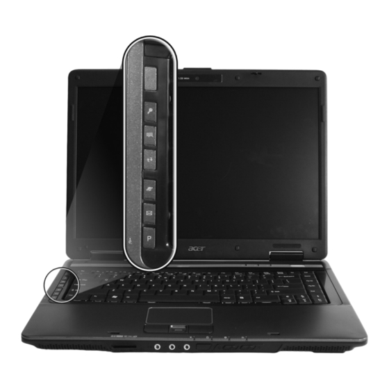
Page 20: Easy-Launch Buttons
“and one user-programmable button. Press “ “ to run the Acer Empowering Technology. The mail and Web browser buttons are pre-set to email and Internet programs, but can be reset by users. To set the Web browser, mail and programmable buttons, run the Acer Launch Manager. -
Page 21: Touchpad Basics
Touchpad Basics The following teaches you how to use the touchpad: Move your finger across the touchpad (2) to move the cursor. Press the left (1) and right (4) buttons located beneath the touchpad to perform selection and execution functions. These two buttons are similar to the left and right buttons on a mouse. Tapping on the touchpad is the same as clicking the left button. - Page 22 Right Button Main touchpad Function Left Button (1) Center button (3) Scroll Click and hold to move up/down/left/right. NOTE: When using the touchpad, keep it - and your fingers - dry and clean. The touchpad is sensitive to finger movement; hence, the lighter the touch, the better the response. Tapping too hard will not increase the touchpad’s responsiveness.
-
Page 23: Using The Keyboard
Using the Keyboard The keyboard has full-sized keys and an embedded numeric keypad, separate cursor, lock, Windows, function and special keys. Lock Keys and embedded numeric keypad The keyboard has three lock keys which you can toggle on and off. Lock key Description Caps Lock... -
Page 24: Windows Keys
Windows Keys The keyboard has two keys that perform Windows-specific functions. Description Windows Pressed alone, this key has the same effect as Windows clicking on the Windows Start button; it launches the Start menu. It can also be used with other keys to provide a variety of functions: <... -
Page 25: Hot Keys
Function Description <Fn> + <F1> Hotkey help Displays help on hotkeys. <Fn> + <F2> Acer eSettings Launches Acer eSettings in Acer Empowering Technology. <Fn> + <F3> Acer ePower Launches Acer ePower Management in Acer Management Empowering Technology. <Fn> + <F4>... -
Page 26: Special Key
Special Key You can locate the Euro symbol and the US dollar sign at the upper-center and/or bottom-right of your keyboard. The Euro symbol Open a text editor or word processor. Either press < > at the bottom-right of the keyboard, or hold <Alt Gr> and then press the <5> key at the upper-center of the keyboard. -
Page 27: Acer Empowering Technology
Acer Empowering Technology The Empowering Technology toolbar makes it easy for you to access frequently used functions and manage your new Acer system. Displayed by default in the upper half of your screen, it provides access to the following utilities: Acer eNet Management hooks up to location-based networks intelligently. - Page 28 Acer eNet Management can save network settings for a location to a profile, and automatically switch to the appropriate profile when you move from one location to another. Settings stored include network connection settings (IP and DNS settings, wireless AP details, etc.), as well as default printer settings. Security and safety concerns mean that Acer eNet Management does not store username and password information.
-
Page 29: Acer Epower Management
To access this utility, select "Acer ePower Management" from the Empowering Technology toolbar, run the program from the Acer Empowering Technology program group in Start menu, or right-click the Windows power icon in the system tray and select "Acer ePower Management". -
Page 30: Acer Epresentation Management
Acer ePresentation Management Acer ePresentation Management lets you project your computer's display to an external display device or projector using the hotkey: <Fn> + <F5>. If auto-detection hardware is implemented in the system and the... -
Page 31: Acer Edatasecurity Management
For projectors and external devices that are not auto-detected, launch Acer ePresentation Management to choose an appropriate display setting. NOTE: If the restored resolution is not correct after disconnecting a projector, or you need to use an external resolution that is not supported by Acer ePresentation Management, adjust your display settings using Display Properties or the utility provided by the graphics vendor. -
Page 32: Acer Elock Management
Acer eLock Management Acer eLock Management is simple yet effective utility that allows you to lock removable storage, optical and floppy drive devices to ensure that data can't be stolen while your system is unattended. Removable Storage Devices — includes USB disk drives, USB pen drives, USB flash drives, USB MP3 drives, USB memory card readers, IEEE 1394 disk drives, and any other removable storage devices that can be mounted as a file system when plugged into the system. -
Page 33: Acer Erecovery Management
To use Acer eLock Management, the Empowering Technology password must be set first. Once set, you can apply locks to any of the devices types. Lock(s) will immediately be set without any reboot necessary, and will remain after rebooting, until removed. -
Page 34: Acer Esettings Management
For more information, please refer to "Acer eRecovery Management" on page 61 in the AcerSystem User's Guide. NOTE: If your computer did not come with a Recovery CD or System CD, please use Acer eRecovery Management's "System backup to optical disc" feature to burn a backup image to CD or DVD. To... -
Page 35: Windows Mobility Center
The Windows Mobility Center collects key mobile-related system settings in one easy-to-find place, so you can quickly configure your Acer system to fit the situation as you change locations, networks or activities. Settings include display brightness, power plan, volume, wireless networking on/off, external display settings, display orientation and synchronization status. -
Page 36: Using The System Utilities
Launching the utility is as easy as pressing one buttons. For more information refer to the NTI Shadow help files. Acer GridVista (dual-display compatible) NOTE: This feature is only available on certain models. To enable the dual monitor feature of the notebook, first ensure that the second monitor is connected, then select Start, Control Panel, Display and click on Settings. - Page 37 Extend my windows desktop onto this monitor Apply Acer GridVista is a handy utility that offers four pre-defined display settings so you can view multiple windows on the same screen. To access this function, please go to Start>All Programs and click on Acer GridVista.
-
Page 38: Launch Manager
Launch Manager Launch Manager allows you to set the four easy-launch buttons located above the keyboard. You can access the Launch Manager by clicking on Start > All Programs > Launch Manager to start the application. Norton Internet Security Norton Internet Security is an anti-virus utility that can protect against viruses, keeping your data safe and secure. -
Page 39: Hardware Specifications And Configurations
Hardware Specifications and Configurations Processor Item Specification CPU type Intel® Core™2 Duo Mobile Processor T7300/T7500/T7700/T7800 (4 MB L2 cache, 2/2.2/2.4/2.6 GHz, 800 MHz FSB), or T7100/ T7250 (2 MB L2 cache, 1.8/2.0 GHz, 800 MHz FSB) Intel® Core™2 Duo Mobile Processor T5250/T5450 (2 MB L2 cache, 1.60/1.73 GHz, 533 MHz FSB) Intel®... - Page 40 Item Specification Cache size 1MB to 4MB (See CPU type) System Memory Item Specification Memory controller Built-in Memory size 0MB (no on-board memory) DIMM socket number 2 sockets Supports memory size per socket 2048MB Supports maximum memory size 4G for 64bit OS(with two 2GB SODIMM) Supports DIMM type DDR 2 Synchronous DRAM Supports DIMM Speed...
- Page 41 Wireless Module 802.11b/g Item Specification Chipset Intel® Wireless WiFi Link 4965AGN (dual-band quad- mode 802.11a/b/g/Draft-N) network connection, supporting Acer SignalUp™ with InviLink™ Nplify™ wireless technology Intel® PRO/Wireless 3945ABG (dual-band tri-mode 802.11a/b/g) Wi-Fi CERTIFIED® network connection, supporting Acer SignalUp™ wireless technology Data throughput...
- Page 42 Hard Disk Drive Interface Item Spindle 5400 RPM 5400 RPM 5400 RPM 5400 RPM speed (RPM) Performance Specifications Buffer size Interface SATA SATA SATA SATA Max. media transfer rate (disk-buffer, Mbytes/s) Data transfer 100 MB/Sec. 150 MB/Sec. 150 MB/Sec. 150 MB/Sec. rate Ultra DMA mode-5 Ultra DMA mode-5...
- Page 43 Combo Drive module Item Specification Loading mechanism Load: Manual Release: (a) Electrical Release (Release Button) (b) Release by ATAPI command (c) Emergency Release Power Requirement Input Voltage 5 V +/- 5 % (Operating) Super-Multi Drive module Item Specification Vendor & model name HLDS Super-Multi Drive GSA-T20N, PHILIPS Super-Multi Drive DS- 8A1P, PIONEER Super-Multi Drive DVR-K17RS Performance Specification...
- Page 44 Super-Multi Drive module Item Specification Input Voltage 5 V +/- 5 % (Operating) Audio Interface Item Specification Audio Controller Realtek ALC883 Azalia and Amplifier Maxim MAX9710 & MAX4411 Audio onboard or optional Built-in Mono or Stereo Stereo Resolution 18 bit stereo full duplex Compatibility HD audio Interface;...
- Page 45 PCMCIA Port Item Specification Number of slots One type-II Access location Left panel Supports ZV (Zoomed Video) port No ZV support Supports 32 bit CardBus System Board Major Chips Item Controller Core logic Mobile Intel® PM965/GM965/960 + ICH8M Express Chipset ATI X2500, HD2400XT or HD2600 Realtek 8100SBL/CL USB 2.0...
- Page 46 Battery Item Specification Package configuration 3 cells in series, 2 series in parallel 4 cells in series, 2 series in parallel Normal voltage 11.1V Charge voltage 19.0 v LCD 15.4” inch Item Specification Vendor & model name AUO B154EW02-V0 (Non- LPL LP154WX4-TLA2 (Non- Glare) Glare)
- Page 47 LCD Inverter Item Specification Input current (mA) 2.56 (max) Output voltage (V, rms) 780V (2000V for kick off) Output current (mA, rms) 6.5 (max) Output voltage frequency (k Hz) 65K Hz (max) AC Adaptor Item Specification Input rating 90V AC to 264V AC, 47Hz to 63Hz Maximum input AC current 1.7A Inrush current...
- Page 48 Chapter 1...
-
Page 49: System Utilities
Chapter 2 System Utilities BIOS Setup Utility The BIOS Setup Utility is a hardware configuration program built into your computer’s BIOS (Basic Input/ Output System). Your computer is already properly configured and optimized, and you do not need to run this utility. However, if you encounter configuration problems, you may need to run Setup. -
Page 50: Navigating The Bios Utility
Navigating the BIOS Utility There are six menu options: Information, Main, Advanced, Security, Boot, and Exit. Follow these instructions: To choose a menu, use the left and right arrow keys. To choose an item, use the up and down arrow keys. To change the value of a parameter, press F5 or F6. -
Page 51: Information
Information The Information screen displays a summary of your computer hardware information. P h o e n i x Tr u s t e d C o r e ( t m ) S e t u p U t i l i t y I n f o r m a t i o n M a i n A d v a n c e d... -
Page 52: Main
Main The Main screen allows the user to set the system time and date as well as enable and disable boot option and recovery. P h o e n i x Tr u s t e d C o r e ( t m ) S e t u p U t i l i t y I n f o r m a t i o n M a i n A d v a n c e d... - Page 53 The table below describes the parameters in this screen. Settings in boldface are the default and suggested parameter settings. Parameter Description Format/Option System Time Sets the system time. The hours are displayed Format: HH:MM:SS with 24-hour format. (hour:minute:second) System Time System Date Sets the system date.
-
Page 54: Advanced
Advanced P h o e n i x Tr u s t e d C o r e ( t m ) S e t u p U t i l i t y I n f o r m a t i o n M a i n A d v a n c e d S e c u r i t y... -
Page 55: Security
Security The Security screen contains parameters that help safeguard and protect your computer from unauthorized use. PhoenixBIOS Setup Utility Security Boot Information Main Exit Item Specific Help Supervisor Password Is : Clear User Password Is : Clear HDD 0 Password Clear Supervisor Password controls accesses of the... -
Page 56: Setting A Password
The table below describes the parameters in this screen. Settings in boldface are the default and suggested parameter settings. Parameter Description Option User Password is Shows the setting of the user password. Clear or Set Supervisor Password is Shows the setting of the Supervisor password Clear or Set Set User Password... -
Page 57: Removing A Password
Removing a Password Follow these steps: Use the w and y keys to highlight the Set Supervisor Password parameter and press the e key. The Set Password box appears: Type the current password in the Enter Current Password field and press e. Press e twice without typing anything in the Enter New Password and Confirm New Password fields. - Page 58 If the current password entered does not match the actual current password, the screen will show you the Setup Warning. If the new password and confirm new password strings do not match, the screen will display the following message. Chapter 2...
-
Page 59: Boot
Boot This menu allows the user to decide the order of boot devices to load the operating system. Bootable devices includes the distette drive in module bay, the onboard hard disk drive and the CD-ROM in module bay. PhoenixBIOS Setup Utility Boot Information Main... -
Page 60: Exit
Exit The Exit screen contains parameters that help safeguard and protect your computer from unauthorized use. PhoenixBIOS Setup Utility Exit Information Main Advanced Security Boot Item Specific Help Exit Saving Changes Exit System Setup and save Exit Disarding Changes your changes to CMOS. Load Setup Defaults Discard Changes Save Changes... -
Page 61: Bios Flash Utility
BIOS Flash Utility The BIOS flash memory update is required for the following conditions: New versions of system programs New features or options Restore a BIOS when it becomes corrupted. Use the Phlash utility to update the system BIOS flash ROM. NOTE: If you do not have a crisis recovery diskette at hand, then you should create a Crisis Recovery Diskette before you use the Phlash utility. -
Page 62: Remove Hdd/Bios Utility
Remove HDD/BIOS Utility This section provide you with removing HDD/BIOS method: Remove HDD Password: If you key in wrong HDD password for three time, “HDD password error code” would display on the screen. See the image below. If you need to solve HDD password locked problem, you can run HDD_PW.EXE Key in “hdd_pw 15494 0”... - Page 63 Remove BIOS Password: If you key in wrong Supervisor Password for three time, “System Disabled” would display on the screen. See the image below. Chapter 2...
- Page 64 If you need to solve BIOS password locked problem, you can run BIOS_PW.EXE Key in “bios_pw 14452 0” Choose one upper-case string Reboot the system and key in “qjjg9vy” or “07yqmjd” to BIOS user password. Chapter 2...
- Page 65 Chapter 2...
- Page 66 Chapter 2...
-
Page 67: Machine Disassembly And Replacement
Chapter 3 Machine Disassembly and Replacement This chapter contains step-by-step procedures on how to disassemble the notebook computer for maintenance and troubleshooting. Disassembly Requirements To disassemble the computer, you need the following tools: Wrist grounding strap and conductive mat for preventing electrostatic discharge Flat screwdriver Philips screwdriver Hex screwdriver... -
Page 68: General Information
General Information Pre-disassembly Instructions Before proceeding with the disassembly procedure, make sure that you do the following: Turn off the power to the system and all peripherals. Unplug the AC adapter and all power and signal cables from the system. Place the system on a flat, stable surface. -
Page 69: External Module Disassembly Process
External Module Disassembly Process External Modules Disassembly Flowchart The flowchart below gives you a graphic representation on the entire disassembly sequence and instructs you on the components that need to be removed during servicing. For example, if you want to remove the main board, you must first remove the keyboard, then disassemble the inside assembly frame in that order. -
Page 70: Removing The Battery Pack
Removing the Battery Pack Turn base unit over. Slide the battery lock/unlock latch to the unlock position (1). Slide and hold the battery release latch to the release position (2), then remove the battery from the main unit (3). Removing the SD dummy card Push the SD dummy card all the way in to eject it (1, 2). -
Page 71: Removing The Pc And Expresscard Dummy Cards
Pull it out from the slot (2). Removing the PC and ExpressCard dummy cards Press the eject button to pop out the button. Press it again (1) to pop out the PC dummy card (2). Remove the PC dummy card from the slot. Chapter 3... -
Page 72: Removing The Lower Cover
Push the ExpressCard dummy card all the way in to eject it. Pull it out from the slot. Removing the Lower Cover See “Removing the Battery Pack” on page 60. See “Removing the SD dummy card” on page 60. See “Removing the PC and ExpressCard dummy cards” on page 61. Remove the seven screws (B) on the lower cover. -
Page 73: Removing The Dimm
Use a plastic screw driver to carefully pry open the lower cover. Remove the lower cover from the lower case. Removing the DIMM See “Removing the Battery Pack” on page 60. See “Removing the SD dummy card” on page 60. See “Removing the PC and ExpressCard dummy cards”... -
Page 74: Removing The Wlan Board Modules
Remove the DIMM module. Removing the WLAN Board Modules See “Removing the Battery Pack” on page 60. See “Removing the SD dummy card” on page 60. See “Removing the PC and ExpressCard dummy cards” on page 61. See “Removing the Lower Cover” on page 62. Remove the tape holding the gray antenna. -
Page 75: Removing The Hard Disk Drive Module
Move the antenna away from the WLAN board and remove the two screws (F) on the WLAN board to release the WLAN board. Step Size (Quantity) Color Torque M2 x L3 (2) Silver 1.6 kgf-cm Detach the WLAN board from the WLAN socket. NOTE: When attaching the antenna back to the WLAN board, make sure the cable are arranged properly. -
Page 76: Removing The Optical Drive Module
Disconnect the hard disk module from the connector by pulling on the mylar tab on the hard disk module. Remove the hard disk module. NOTE: To prevent damage to device, avoid pressing down on it or placing heavy objects on top of it. Remove the hard disk from the hard disk rubber enclosure as shown. - Page 77 Turn the base unit over, then remove the one screw (A) on the bottom side of the unit. Step Size (Quantity) Color Torque M2.5 x L6 (1) Black 3.0 kgf-cm Carefully use a plastic screw driver (1) to eject the optical drive tray (2). Pull the optical drive module out from the main unit.
- Page 78 Remove the one screw (C) securing the locker bracket and remove the locker bracket from the optical disk drive module. Step Size (Quantity) Color Torque M2 x L4 (1) Silver 1.6 kgf-cm Chapter 3...
-
Page 79: Main Unit Disassembly Process
Main Unit Disassembly Process Main Unit Disassembly Flowchart MAIN UNIT DISASSEMBLY MAIN UNIT MIDDLE HEAT SINK FAN COVER MODEM BOARD C x9 (Cx5 for UMA module) Fx 2 CPU/VGA Fx 1 THERMAL MODULE KEYBOARD POWER BOARD A x 2 H x 2 LCD MODULE BOARD A x 14... -
Page 80: Removing The Modem Board
Removing the Modem Board See “Removing the Battery Pack” on page 60. See “Removing the Lower Cover” on page 62. See “Removing the DIMM” on page 63.. See “Removing the WLAN Board Modules” on page 64.. Remove the 2 screws (C) securing the modem card. Step Size (Quantity) Color... -
Page 81: Removing The Cpu And Vga Heatsink Module
Disconnect the heatsink fan connector from FAN1 on the main board. Remove the two screws (C) securing the heatsink fan module. Step Size (Quantity) Color Torque M2 x L4 (2) Silver 1.6 kgf-cm Remove the heatsink fan module from the main board. Removing the CPU and VGA Heatsink Module See “Removing the Battery Pack”... - Page 82 Remove the nine screws (C) securing the CPU and VGA heatsink module in place. Step Size (Quantity) Color Torque M2 x L4 (9) Silver 3.0 kgf-cm NOTE: There are only five (5) screws for the UMA module. Slide out and remove the heatsink module. Chapter 3...
-
Page 83: Removing The Cpu
Removing the CPU See “Removing the Battery Pack” on page 60.. See “Removing the Lower Cover” on page 62.. See “Removing the Heatsink Fan Module” on page 70. See “Removing the CPU and VGA Heatsink Module” on page 71. Using a flat screwdriver, turn the CPU socket latch counter-clockwise to release the CPU, then remove the CPU. -
Page 84: Removing The Middle Cover And The Power Board
Remove the two screws (D) securing the VGA board. Step Size (Quantity) Color Torque M2.5 x L5 (2) Silver 1.6 kgf-cm Carefully remove the VGA board from the main board. Removing the Middle Cover and the Power Board See “Removing the Battery Pack” on page 60. Open the LCD screen all the way to facilitate the easy removal of the middle cover. - Page 85 Detach the cover and turn it over on the keyboard. Disconnect the Power board cable from the main board and disconnect the Power board cable. Chapter 3...
-
Page 86: Removing The Keyboard
Remove the Middle Cover together with the Power board. Remove the one screw (F) securing the Power board to the middle cover, and remove the Power board from the middle cover. Step Size (Quantity) Color Torque M2 x L3 (1) Silver 1.6 kgf-cm Removing the Keyboard... - Page 87 Remove the two screws (F) securing the keyboard to the upper case. Step Size (Quantity) Color Torque M2 x L3 (2) Silver 1.6 kgf-cm Carefully pry the keyboard out of the latch and slide it out; then turn it over on the touchpad area. Chapter 3...
-
Page 88: Removing The Lcd Module
Disconnect the keyboard cable from the main board to remove the keyboard. Removing the LCD Module See “Removing the Battery Pack” on page 60. See “Removing the Lower Cover” on page 62. See “Removing the WLAN Board Modules” on page 64. See “Removing the Middle Cover and the Power Board”... - Page 89 Remove the acetic tape and disconnect the LCD coaxial cable from the LCD1 connector on the main board and release it from the latch. Remove the internal microphone cable from the INTMIC1 connector on the main board. Chapter 3...
- Page 90 Release the wireless LAN antenna cables from the hole and latches as shown. Remove the two screws (A) from the base of the unit. Step Size (Quantity) Color Torque M2.5 x L6 (2) Black 4.0 kgf-cm 10. Remove the two screws (H) from the left and right hinge of the LCD module. Step Size (Quantity) Color...
-
Page 91: Separating The Upper Case From The Lower Case
Separating the Upper Case from the Lower Case See “Removing the Battery Pack” on page 60. See “Removing the SD dummy card” on page 60. See “Removing the PC and ExpressCard dummy cards” on page 61. See “Removing the Lower Cover” on page 62. See “Removing the DIMM”... - Page 92 19. Disconnect the Launch board cable from the SWITCHCN1 from the main board. 20. Disconnect the fingerprint cable (select model only) from the FPCN1 connector on the main board. Chapter 3...
- Page 93 21. Disconnect the touchpad cable from the TOUCHPAD1 on the main board. 22. Remove the fourteen screws (A) on the bottom panel. Step Size (Quantity) Color Torque 1~14 M2.5 x L6 (14) Black 3.0 kgf-cm 23. Gently raise the upper case from the main unit. Chapter 3...
-
Page 94: Removing The Launch Board
Removing the Launch Board See “Removing the Battery Pack” on page 60. See “Removing the SD dummy card” on page 60. See “Removing the PC and ExpressCard dummy cards” on page 61. See “Removing the Lower Cover” on page 62. See “Removing the DIMM”... -
Page 95: Removing Thetouch Pad Board Module
19. Remove the one screw (F) holding the launch board and remove the launch board from the upper cover. Step Size (Quantity) Color Torque M2 x L3 (1) Silver 1.6 kgf-cm Removing theTouch Pad Board Module See “Removing the Battery Pack” on page 60. See “Removing the SD dummy card”... - Page 96 18. Remove the fingerprint cable from the fingerprint board. 19. Remove the touch pad cable from the touch pad board. Chapter 3...
- Page 97 20. Remove the two screws (F) on the touch pad bracket and remove the touch pad bracket from the upper case. Step Size (Quantity) Color Torque M2 x L3 (2) Silver 1.6 kgf-cm 21. Remove the two screws (F) from the fingerprint board. Step Size (Quantity) Color...
-
Page 98: Removing The Main Board
23. Carefully pry loose and remove the touch pad board. WARNING:The touchpad board is glued to the upper case, only remove the touchpad board if it is defective. Removing the main board See “Removing the Battery Pack” on page 60. See “Removing the SD dummy card”... - Page 99 19. Disconnect the speaker cable from the SPKR1 on the main board. 20. Remove the two screws (C) holding the main board. Step Size (Quantity) Color Torque M2 x L4 (2) Silver 1.6 kgf-cm 21. Carefully detach the main board and turn it over to access the USB board cable. 22.
-
Page 100: Removing The Speaker Modules
Removing the Speaker Modules See “Removing the Battery Pack” on page 60. See “Removing the SD dummy card” on page 60. See “Removing the PC and ExpressCard dummy cards” on page 61. See “Removing the Lower Cover” on page 62. See “Removing the DIMM”... -
Page 101: Removing The Usb Board
21. Remove the four screws (C) holding the left and right speakers. Step Size (Quantity) Color Torque M2 x L4 (4) Silver 1.6 kgf-cm 22. Remove the left and right speakers from the upper case. Removing the USB Board See “Removing the Battery Pack” on page 60. See “Removing the SD dummy card”... - Page 102 19. Remove the one screw (C) securing the USB board to the lower case. Step Size (Quantity) Color Torque M2 x L4 (1) Silver 1.6 kgf-cm 20. Partially lift the USB Board from the lower case. 21. Detach the cable from the USB board. Chapter 3...
-
Page 103: Lcd Module Disassembly Process
LCD Module Disassembly Process LCD Module Disassembly Flowchart LCD MODULE DISASSEMBLY LCD MODULE A x 8 LCD BEZEL LCD ASSEMBLY INVERTER BOARD Ex 1 E x 1 RIGHT HINGE LEFT HINGE LCD FPC LEFT LCD RIGHT LCD CABLE BRACKET BRACKET LCD BACK PANEL INTERNAL ANTENNAS... -
Page 104: Removing The Lcd Bezel
Removing the LCD Bezel See “Removing the Battery Pack” on page 60. See “Removing the Lower Cover” on page 62. See “Removing the DIMM” on page 63. See “Removing the WLAN Board Modules” on page 64. See “Removing the Middle Cover and the Power Board” on page 74. See “Removing the Keyboard”... -
Page 105: Removing The Lcd Module With The Brackets
Removing the LCD module with the Brackets See “Removing the Battery Pack” on page 60. See “Removing the Lower Cover” on page 62. See “Removing the DIMM” on page 63. See “Removing the WLAN Board Modules” on page 64. See “Removing the Middle Cover and the Power Board” on page 74. See “Removing the Keyboard”... -
Page 106: Removing The Inverter Board And Fpc Cable
Removing the Inverter Board and FPC Cable See “Removing the Battery Pack” on page 60. See “Removing the Lower Cover” on page 62. See “Removing the DIMM” on page 63. See “Removing the WLAN Board Modules” on page 64. See “Removing the Middle Cover and the Power Board” on page 74. See “Removing the Keyboard”... -
Page 107: Removing The Lcd Brackets
Removing the LCD Brackets See “Removing the Battery Pack” on page 60. See “Removing the Lower Cover” on page 62. See “Removing the DIMM” on page 63. See “Removing the WLAN Board Modules” on page 64. See “Removing the Middle Cover and the Power Board” on page 74. See “Removing the Keyboard”... -
Page 108: Removing The Antennas
10. Remove the two screws (E) securing the left and right hinge to the back cover. Step Size (Quantity) Color Torque M2.5 x L5 (2) Silver 2.5 kgf-cm 11. Remove the left and right hinge from the back cover. Removing the Antennas See “Removing the Battery Pack”... -
Page 109: Removing The Internal Microphone And Web Camera
12. Remove the tapes together with the antenna cables from the back cover. Removing the Internal Microphone and Web Camera See “Removing the Battery Pack” on page 60. See “Removing the Lower Cover” on page 62. See “Removing the DIMM” on page 63. See “Removing the WLAN Board Modules”... - Page 110 14. Remove the internal microphone from the back cover. 15. Remove the Web camera from the back cover. Chapter 3...
-
Page 111: Troubleshooting
Troubleshooting Use the following procedure as a guide for computer problems. NOTE: The diagnostic tests are intended to test only Acer products. Non-Acer products, prototype cards, or modified options can give false errors and invalid system responses. Obtain the failing symptoms in as much detail as possible. -
Page 112: System Check Procedures
System Check Procedures External Diskette Drive Check Do the following to isolate the problem to a controller, driver, or diskette. A write-enabled, diagnostic diskette is required. NOTE: Make sure that the diskette does not have more than one label attached to it. Multiple labels can cause damage to the drive or cause the drive to fail. -
Page 113: Memory Check
External keyboard If any of these devices do not work, reconnect the cable connector and repeat the failing operation. Memory check Memory errors might stop system operations, show error messages on the screen, or hang the system. Boot from the diagnostics diskette and start the doagmpstotics program (please refer to main board. Go to the diagnostic memory in the test items. -
Page 114: Check The Power Adapter
Check the Power Adapter Unplug the power adapter cable from the computer and measure the output voltage at the plug of the power adapter cable. See the following figure Pin 1: +19 to +20.5V Pin 2: 0V, Ground If the voltage is not correct, replace the power adapter. If the voltage is within the range, do the following: Replace the System board. -
Page 115: Touchpad Check
Check the Battery Pack To check the battery pack, do the following: From Software: Check out the Power Management in control Panel In Power Meter, confirm that if the parameters shown in the screen for Current Power Source and Total Battery Power Remaining are correct. -
Page 116: Power-On Self-Test (Post) Error Message
Power-On Self-Test (POST) Error Message The POST error message index lists the error message and their possible causes. The most likely cause is listed first. NOTE: Perform the FRU replacement or actions in the sequence shown in FRU/Action column, if the FRU replacement does not solve the problem, put the original part back in the computer. -
Page 117: Index Of Error Messages
Index of Error Messages Error Code List Error Codes Error Messages Equipment Configuration Error Causes: 1. CPU BIOS Update Code Mismatch 2. IDE Primary Channel Master Drive Error (THe causes will be shown before “Equipment Configuration Error”) Memory Error at xxxx:xxxx:xxxxh (R:xxxxh, W:xxxxh) Real Time Clock Error CMOS Battery Bad CMOS Checksum Error... - Page 118 Error Message List Error Messages FRU/Action in Sequence System timer error RTC battery Run BIOS Setup Utility to reconfigure system time, then reboot system. System board Real time clock error RTC battery Run BIOS Setup Utility to reconfigure system time, then reboot system.
- Page 119 Error Message List No beep Error Messages FRU/Action in Sequence No beep, power-on indicator turns off and Power source (battery pack and power adapter). See “Power LCD is blank. System Check” on page 103.. Ensure every connector is connected tightly and correctly. Reconnect the DIMM.
-
Page 120: Phoenix Bios Beep Codes
Phoenix BIOS Beep Codes Code Beeps POST Routine Description Verify Real Mode Disable Non-Maskable Interrupt (NMI) Get CPU type Initialize system hardware Initialize chipset with initial POST values Set IN POST flag Initialize CPU registers Enable CPU cache Initialize caches to initial POST values Initialize I/O component Initialize the local bus IDE Initialize Power Management... - Page 121 Code Beeps POST Routine Description Advanced configuration of chipset registers Load alternate registers with CMOS values Initialize interrupt vectors POST device initialization 2-1-2-3 Check ROM copyright notice Check video configuration against CMOS Initialize PCI bus and devices Initialize all video adapters in system QuietBoot start (optional) Shadow video BIOS ROM Display BIOS copyright notice...
- Page 122 Code Beeps POST Routine Description Detect and install external RS232 ports Configure non-MCD IDE controllers Detect and install external parallel ports Initialize PC-compatible PnP ISA devices Re-initialize onboard I/O ports Configure Motherboard Configurable Devices (optional) Initialize BIOS Area Enable Non-Maskable Interrupts (NMIs) Initialize Extended BIOS Data Area Test and initialize PS/2 mouse Initialize floppy controller...
- Page 123 Code Beeps POST Routine Description Prepare Boot Initialize DMI parameters Initialize PnP Option ROMs Clear parity checkers Display MultiBoot menu Clear screen (optional) Check virus and backup reminders Try to boot with INT 19 Initialize POST Error Manager (PEM) Initialize error logging Initialize error display function Initialize system error handler PnPnd dual CMOS (optional)
- Page 124 Code Beeps Boot to Mini DOS Clear Huge Segment Boot to Full DOS Chapter 4...
-
Page 125: Index Of Symptom-To-Fru Error Message
Index of Symptom-to-FRU Error Message LCD-Related Symptoms Symptom / Error Action in Sequence LCD backlight doesn't work Enter BIOS Utility to execute “Load Setup Default Settings”, then reboot system. LCD is too dark Reconnect the LCD connectors. LCD brightness cannot be adjusted Keyboard (if contrast and brightness function key doesn't LCD contrast cannot be adjusted work). - Page 126 Power-Related Symptoms Symptom / Error Action in Sequence The system doesn’t power-off. Power source (battery pack and power adapter). See “Power System Check” on page 103. Hold and press the power switch for more than 4 seconds. System board Battery can’t be charged See “Check the Battery Pack”...
- Page 127 Power Management-Related Symptoms Symptom / Error Action in Sequence The system doesn't resume from See “Save to Disk (S4)” on page 38. hibernation mode. Hard disk connection board Hard disk drive System board The system doesn't resume from standby See “Save to Disk (S4)” on page 38. mode after opening the LCD.
- Page 128 Keyboard/Touchpad-Related Symptoms Symptom / Error Action in Sequence Touchpad does not work. Reconnect touchpad cable. Touchpad board System board Modem-Related Symptoms Symptom / Error Action in Sequence Internal modem does not work correctly. Modem phone port modem combo board System board NOTE: If you cannot find a symptom or an error in this list and the problem remains, see “Undetermined Problems”...
-
Page 129: Intermittent Problems
Intermittent Problems Intermittent system hang problems can be caused by a variety of reasons that have nothing to do with a hardware defect, such as: cosmic radiation, electrostatic discharge, or software errors. FRU replacement should be considered only when a recurring problem exists. When analyzing an intermittent problem, do the following: Run the advanced diagnostic test for the system board in loop mode at least 10 times. -
Page 130: Undetermined Problems
System Check” on page 103.): Power-off the computer. Visually check them for damage. If any problems are found, replace the FRU. Remove or disconnect all of the following devices: Non-Acer devices Printer, mouse, and other external devices Battery pack Hard disk drive... -
Page 131: Jumper And Connector Locations
Chapter 5 Jumper and Connector Locations Top View Description Description Power Cable Connector Fingerprint/Touchpad Connector LCD Cable Connector Bluetooth Connector Touchpad Board Connector Speaker Connector Keyboard Connector Chapter 5... -
Page 132: Bottom View
Bottom View Description Description USB Connector SATA Connector Card Reader PC Card Reader Line-out jack LAN Connector Mic-in jack CRT Connector Headphone jack 1394 Connector Chapter 5... - Page 133 Standard Operation Procedures of Password Bypassing and BIOS Recovery For RD and CSD to debug easily, the system provide one hardware DIP switch for Bypassing Password Check, and one Hotkey to enable BIOS Recovery. DIP Switches: Default Setting Description Disabled (High) Bypassing Password Check Hotkey to enable BIOS Recovery: Fn+ESC, then Power Button.
- Page 134 special BIOS block, called BootBlock. RD/CSD can use this special BIOS code to recover the BIOS to a successful one if previous BIOS flashing process fails. However, before doing this, one Crisis Disk should be prepared in WinXP. Detailed steps are as the followings: Prepare the Crisis Disk in WinXP.
-
Page 135: Fru (Field Replaceable Unit) List
Guide. For ACER AUTHORIZED SERVICE PROVIDERS, your Acer office may have a DIFFERENT part number code from those given in the FRU list of this printed Service Guide. You MUST use the local FRU list provided by your regional Acer office to order FRU parts for repair and service of customer machines. -
Page 136: Travelmate 5720/5320 And Extensa 5620/5220 Exploded Diagram
TravelMate 5720/5320 and Extensa 5620/5220 Exploded Diagram TravelMate 5720/5320 and Extensa 5620/5220 FRU List Category Part Name and Description Acer Part No. Adapter ADAPTER 90W DELTA ADP-90SB AP.09001.010 BBDAR ADAPTER 90W DELTA ADP-90SB AP.09001.013 BBEA LF ADAPTER 90W LITEON PA-1900- AP.09003.005... - Page 137 Category Part Name and Description Acer Part No. BATTERY PACK LI+ 6CELL 2.0MAH BT.00603.029 SANYO BATTERY PACK LI+ 6CELL 2.0MAH BT.00604.015 SONY BATTERY PACK LI 6CELL 2.0MAH BT.00605.014 PANASONIC BATTERY PACK LI 6CELL 2.0MAH BT.00607.008 SIMPLO BATTERY PACK LI+ 8CELL 2.4MAH BT.00803.022...
- Page 138 Category Part Name and Description Acer Part No. TOUCHPAD SCROLL-KEY BOARD 56.TKC01.001 COLUMBIA 06587-1 TOUCHPAD BOARD SYNAPTICS 56.TK901.001 TM00372-012 INVERTER BOARD 17” DARFON 19.TK901.001 VK.21189.801 INVERTER BOARD 17” FOXCONN 19.TK901.002 T62I249.00 INVERTER BOARD 17” YEC YNV- 19.TK901.004 MODEM BOARD FOXCONN FX.22500.009...
- Page 139 Category Part Name and Description Acer Part No. POWER CORD 10A 125V US 27.T30V1.001 POWER CORD 10A 125V 3PIN US 27.01518.641 POWER CORD 2.5A 125V 8121- 27.01518.781 USA/W CNS POWER CORD 220V 3PIN EUR 27.T30V1.004 POWER CABLE 16A 250V 3PIN EUR 27.01518.731...
- Page 140 Category Part Name and Description Acer Part No. LOWER CASE W/SPEAKER ASSY L- 60.TKA01.001 CASE COLUMBIA UNITLOAD COVER W/DASP ASSY 60.TK901.007 BIG DOOR HDD DASP COLUMBIA UPPER CASE W/ COVER SWITCH 60.TKC01.002 CABLE UNIT LOAD COVER L-CASE DOOR 60.TK901.003 ASSEMBLY OPTICAL BRACKET 33.TK901.002...
- Page 141 Category Part Name and Description Acer Part No. CPU INTEL MEROM CORE2DUAL KC.73001.DTP T7300 2.0G 4M 800L CPU INTEL MEROM CORE2DUAL KC.75001.DTP T7500 2.2G 4M 800 CPU INTEL MEROM CORE2DUAL KC.77001.DTP T7700 2.4G 4M 800L DVD-RW Drive ASSEMBLY SUPLER MULTI 6M.TK901.002...
- Page 142 Category Part Name and Description Acer Part No. HDD 160GB 5400RPM SATA HGST KH.16007.011 HTS541616J9SA00 SURUGA-B LF HDD 160GB 5400RPM SATA WD KH.16008.019 WD1600BEVS-22RST0 ML80 LF HEATSINK CPU HEATSINK ASSY COLUMBIA 60.TKC01.003 INTEL UMA FORCE Keyboard KEYBOARD 14_15KB-EV2 88KS KB.INT00.002...
- Page 143 Category Part Name and Description Acer Part No. KEYBOARD 14_15KB-EV2 88KS KB.INT00.024 BLACK GREEK (BIG ERGO) DARFON KEYBOARD 14_15KB-EV2 89KS KB.INT00.025 BLACK GERMAN (BIG ERGO) DARFON KEYBOARD 14_15KB-EV2 89KS KB.INT00.026 BLACK FRENCH (BIG ERGO) DARFON KEYBOARD 14_15KB-EV2 89KS KB.INT00.029 BLACK DANISH (BIG ERGO)
- Page 144 Category Part Name and Description Acer Part No. CAMERA CMOS 0.3M SUYIN 57.TK901.001 CN0314-OV03 UVC Communication Module WIRELESS ANTENNA RIGHT 25.TK901.001 WIRELESS ANTENNA LEFT 25.TK901.002 Microphone MICROPHONE CABLE 23.TK901.003 Main Board MAINBOARD TM5720 INTEL PM965 MB.TK301.001 ICH8M 256M-GD2 BCM578MKMLG LF W/ 1394 & FIR & DVI W/ MODEM &...
- Page 145 Chapter 6...
-
Page 146: Model Definition And Configuration
Appendix A Model Definition and Configuration TravelMate 5720/5320 Series Acer Wirele Descriptio DIMM DIMM HDD 1 Blueto VOIP Model Country Part (GB) Phone AS505 India LX.AV AS5051AN ATMK N14.1 SO512 N80G NSM8 ABT_ 1ANW 30C.0 WXMi WXGA MBII5 B5.4K ATH54... - Page 147 Acer Wirele Descriptio DIMM DIMM HDD 1 Blueto VOIP Model Country Part (GB) Phone AS505 USA/ LX.AV AS5051AW ATMK N14.1 SO512 SO512 N120 NSM8 ABT_ 1AWX Canada - 30J.00 WXGA MBII5 MBII5 GB5.4 ATH54 Canadian MCECF 13BG French UMAC 2*512/120/ 6L/5R/ CB_bg_0.3...
- Page 148 Acer Wirele Descriptio DIMM DIMM HDD 1 Blueto VOIP Model Country Part (GB) Phone AS505 Thailand LX.AV AS5051AW ATMK N14.1 SO512 N120 NSM8 ABT_ 1AWX 305.00 WXGA MBII5 GB5.4 ATH54 XPHTH2 13BG UMAC 1*512/120/ 6L/5R/ CB_bg_0.3 C_AN AS505 Vietnam LX.AV...
- Page 149 Acer Wirele Descriptio DIMM DIMM HDD 1 Blueto VOIP Model Country Part (GB) Phone AS505 GCTWN LX.AV AS5051AW ATMK N14.1 SO512 N120 NSM8 ABT_ FOX_ 1AWX 305.01 WXGA MBII5 GB5.4 ATH54 BRM_ XPHTC1 13BG UMAC 1*512/120/ BT/6L/5R/ CB_bg_0.3 C_AN AS505 GCTWN LX.AV...
- Page 150 Acer Wirele Descriptio DIMM DIMM HDD 1 Blueto VOIP Model Country Part (GB) Phone AS505 Thailand LX.AV AS5051AW ATMK N14.1 SO1G N120 NSM8 ABT_ 1AWX 30J.01 WXGA BII6 GB5.4 ATH54 MCETH1 13BG UMAC 1*1G/120/ 6L/5R/ CB_bg_0.3 C_AN AS505 Vietnam LX.AV...
- Page 151 Acer Wirele Descriptio DIMM DIMM HDD 1 Blueto VOIP Model Country Part (GB) Phone AS505 Thailand LX.AV AS5052WX ATTL5 N14.1 SO1G N120 NSM8 ABT_ 2WXM 30J.00 WXGA BII6 GB5.4 ATH54 MCETH1 13BG UMAC 1*1G/120/ 6L/5R/ CB_bg_0.3 C_AN AS505 Vietnam LX.AV...
- Page 152 Acer Wirele Descriptio DIMM DIMM HDD 1 Blueto VOIP Model Country Part (GB) Phone AS505 Philippines LX.AV AS5051AN ATMK N14.1 SO512 N60G NSM8 ABT_ 1ANW 30C.0 WXMi WXGA MBII5 B5.4K ATH54 LINPUSPH 13BG 1 UMAC 1*512/60/ 6L/5R/ CB_bg_0.3 C_AN AS505 Malaysia LX.AV...
- Page 153 Acer Wirele Descriptio DIMM DIMM HDD 1 Blueto VOIP Model Country Part (GB) Phone AS505 EMEA Eastern LX.AV AS5051AW ATMK N14.1 SO512 SO512 N100 NSM8 ABT_ 1AWX Europe 30J.03 WXGA MBII6 MBII6 GB5.4 BRM4 MCECS5 318BG UMAC 2*512/100/ 5R_bg_0.3 C_AN...
- Page 154 Acer Wirele Descriptio DIMM DIMM HDD 1 Blueto VOIP Model Country Part (GB) Phone AS505 EMEA Slovenia/ LX.AV AS5051AW ATMK N14.1 SO512 SO512 N100 NSM8 ABT_ 1AWX Croatia 30J.03 WXGA MBII6 MBII6 GB5.4 BRM4 MCESI1 318BG UMAC 2*512/100/ 5R_bg_0.3 C_AN...
- Page 155 Acer Wirele Descriptio DIMM DIMM HDD 1 Blueto VOIP Model Country Part (GB) Phone AS505 EMEA France LX.AV AS5051AW ATMK N14.1 SO512 SO512 N100 NSM8 ABT_ 1AWX 30J.02 WXGA MBII6 MBII6 GB5.4 BRM4 MCEWFR1 318BG 1W UMAC 2*512/100/ 5R_bg_0.3 C_AN...
- Page 156 Acer Wirele Descriptio DIMM DIMM HDD 1 Blueto VOIP Model Country Part (GB) Phone AS505 EMEA Holland LX.AV AS5051AW ATMK N14.1 SO512 SO512 N100 NSM8 ABT_ 1AWX 305.02 WXGA MBII6 MBII6 GB5.4 BRM4 XPHNL1 318BG UMAC 2*512/100/ 5R_bg_0.3 C_AN AS505...
- Page 157 Acer Wirele Descriptio DIMM DIMM HDD 1 Blueto VOIP Model Country Part (GB) Phone AS505 EMEA South LX.AV AS5051AW ATMK N14.1 SO512 SO512 N100 NSM8 ABT_ 1AWX Africa 305.01 WXGA MBII6 MBII6 GB5.4 BRM4 XPHSA1 318BG UMAC 2*512/100/ 5R_bg_0.3 C_AN...
- Page 158 Acer Wirele Descriptio DIMM DIMM HDD 1 Blueto VOIP Model Country Part (GB) Phone AS505 USA/ LX.AV AS5052WX ATTL5 N14.1 SO512 SO512 N120 NSM8 ABT_ 2WXM Canada - 30J.02 Mi MCEUS WXGA MBII5 MBII5 GB5.4 ATH54 Canadian UMAC 13BG French...
- Page 159 Acer Wirele Descriptio DIMM DIMM HDD 1 Blueto VOIP Model Country Part (GB) Phone AS505 EMEA Russia LX.AV AS5051AW ATMK N14.1 SO512 N100 NSM8 ABT_ FOX_ 1AWX 30J.05 WXGA MBII6 GB5.4 BRM4 BRM_ VoIP MCERU9 318BG PCMC UMAC 1*512/100/ BT/6L/5R/ CB_bg_VP _0.3C_AN...
- Page 160 Acer Wirele Descriptio DIMM DIMM HDD 1 Blueto VOIP Model Country Part (GB) Phone AS505 EMEA Middle LX.AV AS5051AN ATMK N14.1 SO512 N60G NSM8 ABT_ FOX_ 1ANW East 30C.0 WXMi WXGA MBII5 B5.4K BRM4 BRM_ LINPUSAR 318BG 7 UMAC 1*512/60/ BT/6L/ 5R_bg_0.3...
- Page 161 Acer Wirele Descriptio DIMM DIMM HDD 1 Blueto VOIP Model Country Part (GB) Phone AS505 EMEA Switzerland LX.AV AS5051AW ATMK N14.1 SO512 SO512 N120 NSM8 ABT_ 1AWX 30J.06 WXGA MBII5 MBII5 GB5.4 BRM4 MCESW8 318BG UMAC 2*512/120/ 6L/5R/ CB_bg_0.3 C_AN...
- Page 162 Acer Wirele Descriptio DIMM DIMM HDD 1 Blueto VOIP Model Country Part (GB) Phone AS505 EMEA Holland LX.AV AS5051AW ATMK N14.1 SO512 SO512 N120 NSM8 ABT_ 1AWX 30J.06 WXGA MBII5 MBII5 GB5.4 BRM4 MCENL6 318BG UMAC 2*512/120/ 5R_bg_0.3 C_AN AS505...
- Page 163 Acer Wirele Descriptio DIMM DIMM HDD 1 Blueto VOIP Model Country Part (GB) Phone AS505 EMEA Eastern LX.AV AS5051AW ATMK N14.1 SO512 SO512 N120 NSM8 ABT_ 1AWX Europe 30J.06 WXGA MBII5 MBII5 GB5.4 BRM4 MCEPL7 318BG UMAC 2*512/120/ 5R_bg_0.3 C_AN...
- Page 164 Acer Wirele Descriptio DIMM DIMM HDD 1 Blueto VOIP Model Country Part (GB) Phone AS505 EMEA Germany LX.AV AS5051AW ATMK N14.1 SO512 SO512 N120 NSM8 ABT_ 1AWX 305.05 WXGA MBII5 MBII5 GB5.4 BRM4 XPHDE7 318BG UMAC 2*512/120/ 5R_bg_0.3 C_AN AS505...
- Page 165 Acer Wirele Descriptio DIMM DIMM HDD 1 Blueto VOIP Model Country Part (GB) Phone AS505 EMEA Greece LX.AV AS5051AW ATMK N14.1 SO512 SO512 N120 NSM8 ABT_ 1AWX 305.05 WXGA MBII5 MBII5 GB5.4 BRM4 XPHEL1 318BG UMAC 2*512/120/ 5R_bg_0.3 C_AN AS505...
- Page 166 Acer Wirele Descriptio DIMM DIMM HDD 1 Blueto VOIP Model Country Part (GB) Phone AS505 EMEA Russia LX.AV AS5051AW ATMK N14.1 SO512 SO512 N120 NSM8 ABT_ 1AWX 305.04 WXGA MBII5 MBII5 GB5.4 BRM4 XPHRU2 318BG UMAC 2*512/120/ 5R_bg_0.3 C_AN AS505...
- Page 167 Acer Wirele Descriptio DIMM DIMM HDD 1 Blueto VOIP Model Country Part (GB) Phone AS505 India LX.AV AS5052N ATTL5 N14.1 SO512 N80G NSM8 ABT_ FOX_ 2NWX 30C.0 WXMi WXGA MBII5 B5.4K ATH54 BRM_ LINPUSIL1 13BG UMAC 1*512/80/ BT/6L/5R/ CB_bg_0.3 C_AN...
-
Page 168: Extensa 5620/5220 Series
Extensa 5620/5220 Series Acer Count Descriptio DIMM DIMM HDD 1 Wireless Bluetoot Model Part (GB) AS305 GCTW S2.AV AS3053WX SMP64342 N14.1W SO512 SO512 N60GB5. NCB2 ABT_AT FOX_BR 3WXCi 205.00 Ci XPHTC1 MBII5 MBII5 H5413B M_2.0 UMAC 2*512/60/ BT/6L/ 5R_bg_0.3 C_AN... - Page 169 Acer Count Descriptio DIMM DIMM HDD 1 Wireless Bluetoot Model Part (GB) AS305 Vietna LX.AV AS3053N SMP64342 N14.1W SO512 N60GB5. NSM8 ABT_BR 3NWX 20C.0 WXMi XGAG MBII5 M4318B LINPUSVN 1 UMAC 1*512/60/ 6L/5R/ CB_bg_0.3 C_AN AS305 USA/ LX.AV AS3053WX SMP64342 N14.1W...
- Page 170 Acer Count Descriptio DIMM DIMM HDD 1 Wireless Bluetoot Model Part (GB) AS305 Indone LX.AV AS3053WX SMP64342 N14.1W SO512 N60GB5. NSM8 ABT_BR 3WXM 205.00 Mi XPHIN1 XGAG MBII5 M4318B UMAC 1*512/60/ 6L/5R/ CB_bg_0.3 C_AN AS305 USA/ LX.AV AS3053WX SMP64342 N14.1W SO512 N80GB5.
- Page 171 Acer Count Descriptio DIMM DIMM HDD 1 Wireless Bluetoot Model Part (GB) AS305 EMEA Middle LX.AV AS3053WX SMP64342 N14.1W SO512 N60GB5. NCB2 ABT_BR 3WXCi East 205.01 MBII5 M4318B XPHAR8 UMAC 1*512/60/ 5R_bg_0.3 C_AN AS305 EMEA Middle LX.AV AS3053WX SMP64342 N14.1W SO512 N60GB5.
- Page 172 Acer Count Descriptio DIMM DIMM HDD 1 Wireless Bluetoot Model Part (GB) AS305 ACLA- LX.AV AS3053WX SMP64342 N14.1W SO512 N60GB5. NSM8 ABT_BR 3WXM Portug 205.01 XGAG MBII5 M4318B uese XPHXC1 UMAC 1*512/60/ 6L/5R/ CB_bg_0.3 C_AN AS305 EMEA Turkey LX.AV AS3053N SMP64342 N14.1W...
-
Page 173: Test Compatible Components
Appendix B Test Compatible Components This computer’s compatibility is tested and verified by Acer’s internal testing department. All of its system ® ® functions are tested under Windows XP Home, Windows XP Pro environment. Refer to the following lists for components, adapter cards, and peripherals which have passed these tests. -
Page 174: Microsoft® Windows® Vista Environment Test
Specification CRT Port Test CRT Monitor Acer 211c 21”, ViewSonic G220F, ViewSonic PF790 19” LCD Monitor Acer FP751 17” TFT LCD, Acer AL1521, Acer AL1721, ViewSonic VD201b, Westinghouse W37G, HP LP2065, HP S9500 Projector Dell 3300MP USB Port Test USB Keyboard/Mouse... - Page 175 Item Specification PCMCIA Test LAN/Modem Card TDK CardBus Ethernet 10/100 32-Bit CBE-10/100BTX Storage Card Hitachi Microdrive 4G 1394 Card Buffalo 1394 Interface Cardbus (IFC-ILCB/DV) USB2.0 Card IBM EtherJet CardBus Adapter 10/100 Wireless Lan Card Cisco Wireless LAN Card 802.11a (Not recommended for wireless ready NETGEAR Wireless LAN card 802.11a model) ISDN Card...
- Page 176 Appendix B...
-
Page 177: Online Support Information
This section describes online technical support services available to help you repair your Acer Systems. If you are a distributor, dealer, ASP or TPM, please refer your technical queries to your local Acer branch office. Acer Branch Offices and Regional Business Units may access our website. However some information sources will require a user i.d. - Page 178 Appendix C...
-
Page 179: Index
Index AFLASH Utility Error Symptom-to-Spare Part Index Antennas Euro Audio External CD-ROM Drive Check External Module Disassembly Flowchart Battery Pack BIOS Features package password control Flash Utility ROM size fpc cable ROM type vendor FRU (Field Replaceable Unit) List Version BIOS Supports protocol 39–51 BIOS Utility... - Page 180 System LCD Brackets Block Diagram LCD Module Disassembly System Check Procedures Flowchart LCD with the Brackets System Memory lower cover System Utilities Main Unit Disassembly Test Compatible Components Flowchart Mainboard Touch Pad Board media access touchpad on indicator hotkey Memory Check Touchpad Check Middle Cover and Power Board Troubleshooting...