Table of Contents
Advertisement
Quick Links
Advertisement
Table of Contents

Related Manuals for Motorola MaxTrac 100


Summary of Contents for Motorola MaxTrac 100
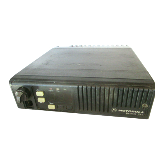
- Page 1 MaxTrac 100 /MaxTrac 300 Mobile Radios MaxTrac...
- Page 2 operating instructions MaxTrac...
-
Page 3: Table Of Contents
Talk–Back Scan .................17 Nuisance–Channel Delete Feature ............17 Scan Rates..................17 , Motorola, MaxTrac, MaxTrac 100, MaxTrac 300, MDC-1200, Quik-Call, Channel Scan, and Call Alert are trademarks of Motorola. © 1995, 1992, 1989 by Motorola, Radio Products Group 8000 W. Sunrise Blvd., Ft. Lauderdale, FL 33322 Printed in U.S.A. - Page 4 Antenna Mounting ................24 Radio Mounting .................25 Begin Installation ..................26 DC Power Cable Installation..............26 Non–Locking Trunnion Installation............28 Sleeve–Mounting Bracket Installation ............30 Service ....................32 Related Publications ................32 Product Service Information..............33 Parts Information..................33 Computer Software Copyrights..............34 MaxTrac 100 /MaxTrac 300 Mobile Radios Contents (cont.)
-
Page 5: Maxtrac 300
This manual is designed to acquaint you with all the features, care, and installation of your MaxTrac mobile radio (henceforth referred to as radio) in order to better serve all your communication needs. MaxTrac 100 and MaxTrac 300 Features... -
Page 6: Maxtrac 300 , 900Mhz Features
MaxTrac 300 , 900MHz Features The MaxTrac 300 900MHz radios have incorporated a few minor changes from the existing (non-900MHz) conventional MaxTrac 300 models. These changes are described below: The front panel of the 900MHz MaxTrac 300 6-channel model with the selective signalling option differs from the corresponding non-900MHz MaxTrac 300 6-channel model as follows: •... -
Page 7: Signalling Types
32-channel models ship standard from the factory with Quik-Call II signalling enabled. On signalling-equipped models, the radio service software (RSS) can be used to enable and disable different features. Contact your Motorola representative or contact your local Motorola service center for additional information. -
Page 8: Maxtrac 100/300 Operation
MaxTrac 100/300 Operation PRIORITY BLANKER DISABLED TRANSMIT/BUSY (SEGMENT ON LOWBAND ONLY) ON/OFF MODE MONITOR VOLUME MaxTrac MAEPF-22597-O MICROPHONE MODE SCAN CONNECTOR DOWN MONITOR SELECT MaxTrac 300 (16-Channel) Model Turning the Radio On To turn the radio on, rotate the On/Off Volume knob clockwise until it clicks. A short chirp tone will be heard if the radio passes the radio self-check test. -
Page 9: Standard Receive Operation
Mon on MaxTrac 300 radio) for 2 seconds (for low-band radio, release after two chirps). This unmutes the speaker and the busy LED (Bsy on MaxTrac 100 radio or Tx/Bsy on MaxTrac 300 radio) will flash. If necessary, reset the volume to a comfortable listening level. -
Page 10: Low-Band Extender Feature
Do not transmit if anyone else is using the channel. The busy LED (Bsy on MaxTrac 100 radio or Tx/Bsy on MaxTrac 300 radio) will flash if there is another carrier on the channel. If the channel is clear, press the PTT (push-to-talk) button on the side of the microphone. -
Page 11: Signalling Operation
“SC” or calling ID. The radio will unmute and a voice message will follow. After the transmission is completed, the radio returns to normal operation. Mode Tx/Bsy Mon Monitor Exit Select MaxTrac 100 MaxTrac 300 (6-Channel) MaxTrac 100/300 Operation (cont.) Signalling Operation... -
Page 12: Receiving A Call Alert
900MHz 6-channel radio) or turn the external switch on the alarm relay cable to the ON position on a MaxTrac 100 radio. On a MaxTrac 300 radio, the display will show “HL.” To disable this feature, press the Select, Call, Exit, or H/L button. -
Page 13: Sending An Identification Number
Whenever an operator in the system presses the PTT key, the unit identification number (ID) will be shown on the display for 10 seconds or less if another incoming ID is received. Exit Select MaxTrac 300 MaxTrac 100/300 Operation (cont.) Signalling Operation (cont.) -
Page 14: Activating The Call List For Sending Selective Messages
PTT button will send the message. The display will revert to the pre-programmed transmit channel to send the signalling message, and the channel will be briefly displayed while the message is being transmitted. MaxTrac 100/300 Operation (cont.) Signalling Operation (cont.) -
Page 15: Receiving An Acknowledgement
The second step requires the use of an external push button or footswitch. Only a press of the external switch will clear the emergency display. MaxTrac 100/300 Operation (cont.) Signalling Operation (cont.) -
Page 16: Channel Scan
Channel Scan Feature (MaxTrac 300 16-/32-Channel Radios Only) Description If your radio is the MaxTrac 300 16-channel or 32-channel model, it includes Channel Scan monitoring. The radio may come with pre-programmed scan lists dedicated to every active channel (channel-slaved). The user selects a particular channel and turns on scan, choosing either “scan”... -
Page 17: Operation
Operation To turn scan on or off, press the Scan button. The radio will only scan when on-hook. The channel display will blank, and a green, horizontal segment(s) will light to indicate which type of scan is functional. For your convenience, the display will indicate the most recently selected scan status. -
Page 18: Pre-Programmed Scan
Pre–Programmed Scan Each active channel in the radio can have a pre-programmed scan list dedicated to it. Through the use of radio service software (RSS) and a computer at a service location, any combination of sequential frequencies may be programmed into each active list. Priority one is always assigned to the selected channel. -
Page 19: Talk-Back Scan
Talk–Back Scan In addition to changing pre-programmed (channel-slaved) scan lists and the second priority channel, the radio service software (RSS) also provides the capability for “talk-back” scan. If this feature is enabled, the radio will remain on the active channel when the microphone is taken off-hook instead of returning to the selected (home) channel. -
Page 20: Field Programming Capabilities
Field Programming Capabilities The radio uses non-volatile memory to store customer unique information. If a frequency, squelch code or channel-slaved scan list needs to be changed, it can be done at a service location with radio service software (RSS). The time-out timer can be disabled or changed to any duration from 1 to 255 seconds. -
Page 21: Fcc Licensing Information
(frequency stability, deviation, and power) be checked before the station is placed in service if modified. Remember: The efficiency of the equipment depends upon a good installation. Motorola recommends that adjustments to this equipment be made ONLY by a certified technician. FCC Licensing Information... -
Page 22: Safety Information
TURN THE RADIO OFF when near electrical blasting caps or in an explosive atmosphere. • All equipment must be properly grounded according to Motorola installation instructions for safe operation. • All equipment should be serviced only by a qualified technician. -
Page 23: Installation Safety Warnings
Installation Safety Warnings Consider the occupants’ safety when you choose a location for the radio. Do not mount the radio overhead or on a sidewall unless you take special precautions. If someone were to remove the radio and fail to replace it properly, road shock could bump the radio loose, and the falling radio could, in some circumstances, cause serious injury to the driver or a passenger. -
Page 24: Operational Safety Warnings
This warning applies to all two-way radio equipment radiating in excess of seven (7) watts RF power. Motorola strongly recommends that any product that converts high-power equipment for portable operation not be used. -
Page 25: Installation Planning And Procedures
Installation Planning and Procedures Testing and Maintenance Your MaxTrac radio is completely adjusted, tested, and inspected before shipment. However, FCC regulations state that a station license must be obtained for each radio installation (radio or base) by the owner of the equipment. The station licensee is responsible for ensuring the transmitter power, frequency, and deviation are within the limits permitted under the station license. -
Page 26: Installation Planning - Mobile Radios
Installation Planning - Mobile Radios Planning is the key to fast, easy radio installation. Before a hole is drilled or a wire is run, inspect the vehicle and determine how and where you intend to mount the antenna, radio, and accessories. Plan wire and cable runs to provide maximum protection from pinching, crushing, and overheating. -
Page 27: Radio Mounting
Radio Mounting Non-Locking Trunnion/High-Power Sleeve The standard, non-locking trunnion (or sleeve used on low–band, 35–watt 800MHz or 30–watt 900MHz models) allows the radio to be mounted to a variety of mounting surfaces. Be sure the mounting surface is able to adequately support the weight of the radio. -
Page 28: Begin Installation
Begin Installation DC Power Cable Installation This MaxTrac radio must be operated only in negative-ground electrical systems. Reverse polarity does not damage the radio; however, radio protection circuits cause the cable fuse to open. Check the vehicle ground polarity before you begin installation to prevent wasted time and effort. - Page 29 (4) Locate the nearest available vehicle chassis-ground mounting point and shorten the black led to remove excess cable length. (5) Install ring lugs (supplied) onto the stripped end of the power cable black lead. Also install a ring lug onto the stripped end of the red lead on the fuse holder as shown in Figure 2.
-
Page 30: Non-Locking Trunnion Installation
Non–Locking Trunnion Installation Select the location to mount your radio either on the TRANSMISSION HUMP OR BELOW THE DASH (see Figure 4). Using the trunnion-mounting bracket as a template, mark the positions of the holes on the mounting surface. Use the innermost four holes for a curved mounting surface such as the transmission hump, and the four outmost holes for a flat surface such as under the dash. - Page 31 TRANSMISSION HUMP MOUNTING THUMB SCREW MOUNTING SURFACE TRUNNION MOUNTING BRACKET BELOW DASH MOUNTING Note: NOTE: Consult your Motorola Consult your Motorola Representative for Overhead Representative for Overhead MOUNTING SURFACE Mounting Precautions. Mounting Precautions THUMB SHEET METAL SCREW SCREWS Figure 4.
-
Page 32: Sleeve-Mounting Bracket Installation
To mount your radio on the floor, an optional accessory, the mounting wedge, is available (Motorola kit number HLN9450). Dash mount your radio as follows: Select the location to mount your radio either ON THE DASH or BELOW THE DASH (see Figure 5). - Page 33 TORX SCREW M5X.8X10 NUT HEX M5X.8 TAPERED STUD SLEEVE MOUNTING BRACKET MOUNTING SURFACE SLEEVE THUMB MOUNTING SCREW BRACKET MOUNTING SURFACE Figure 5. Sleeve Mount for Radio Begin Installation (cont.) Sleeve–Mounting Bracket Installation (cont.)
-
Page 34: Service
Service Proper repair and maintenance procedures will assure efficient operation and long life for this product. A Motorola maintenance agreement will provide expert service to keep this and all other communication equipment in perfect operating condition. A nationwide service organization is provided by Motorola to support maintenance and installation program. -
Page 35: Product Service Information
Product Service Information If any questions arise, please call Florida Product Services. 1-800-523-4007 or 1-305-475-5269 TELEX: 441464 MOTC UI FAX: 1-305-475-5984 Parts Information 7:00 am - 7:00 pm (CST) Monday - Friday (Chicago, U.S.A.) Domestic (U.S.A.) 1-800-422-4210 1-800-826-1913 (Federal Government) TELEX: 280127 FAX: 1-708-538-8198 FAX: 1-301-925-2690 (Federal Government) -
Page 36: Computer Software Copyrights
Motorola. Furthermore, the purchase of Motorola equipment shall not be deemed to grant either directly or by implication, estoppel, or otherwise, any license under the copyrights, patents or patent applications of Motorola, except for the normal nonexclusive, royalty free license to use that arises by operation of law in the sales of a product. - Page 37 Motorola *6880901Z04-A* 8000 West Sunrise Boulevard Fort Lauderdale, Florida 33322 68P80901Z04-A...