Toshiba NB200 Maintenance Manual
Hide thumbs
Also See for NB200:
- User manual (143 pages) ,
- Manual del usuario (204 pages) ,
- User manual (138 pages)
Table of Contents
Advertisement
Quick Links
Advertisement
Chapters
Table of Contents
Troubleshooting

Related Manuals for Toshiba NB200


Summary of Contents for Toshiba NB200
- Page 1 Chapter 1 Hardware Overview...
-
Page 2: Table Of Contents
1 Hardware Overview Chapter 1 Contents Features ........................1-1 2.5-inch HDD ......................1-9 Power Supply ....................... 1-10 Batteries........................ 1-12 1.4.1 Main Battery ..................1-12 1.4.2 Battery Charging Control ..............1-12 1.4.3 RTC Battery..................1-13 NB200 Maintenance Manual 1-ii... - Page 3 1 Hardware Overview Figures Figure 1-1A ID Parts Description Placement Part A............1-5 Figure 1-2 S-ATA HDD ....................1-9 Tables Table 1-1 HDD Specifications ..................1-9 Table 1-2 Quick/Normal Charging Time ..............1-12 NB200 Maintenance Manual 1-iii...
-
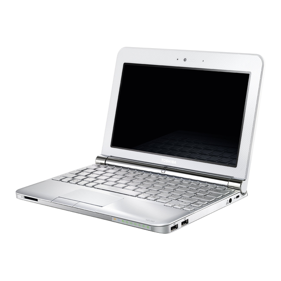
Page 5: Features
Error! Style not defined. Error! Style not defined. 1 Hardware Overview Features ® The Toshiba NB200 is a small-size PC notebook equipped with an Intel Atom Processor, providing high-speed processing capabilities and advanced features. The computer employs a lithium ion battery that allows it to be battery-operated for long periods of time. The display uses 10.1-inch WSVGA LCD panel. - Page 6 (mode 1-4) Bridge Media Slot This slot allows you to insert SD/SDHC, MiniSD/ MicroSD (through adapter) and MMC memory cards. This model does not support CF cards, SmartMedia cards and Memory Sticks. NB200 Maintenance Manual...
- Page 7 The 3G module employs a PCI Express Mini Card. It enables computer users to have mobile access to the internet or to a corporate network. The computer is equipped with either a Ericsson F3507g model (which supports HSPA) or with a Qualcomm Gobi model (which supports HSPA and EVDO). NB200 Maintenance Manual...
- Page 8 When implemented, Bluetooth provides wireless communication in a small space. This module is Version 2.1 + EDR (Antenna on Module type), basically Toshiba stack support it. NB200 Maintenance Manual...
-
Page 9: Figure 1-1A Id Parts Description Placement Part A
Figure 1-1A shows the computer and its system unit configuration. External monitor port Thermal vent holes USB ( USB Sleep and Charge function is supported by this port only. ) Figure 1-1A ID Parts Description Placement Part A NB200 Maintenance Manual... -
Page 10: Hardware Overview
DEPARTMENT EXCEPT AS AUTHORIZED BY COMPAL ELECTRONICS, INC. NEITHER THIS SHEET NOR THE INFORMATION IT CONTAINS MAY BE USED BY OR DISCLOSED TO ANY THIRD PARTY WITHOUT PRIOR WRITTEN CONSENT OF COMPAL ELECTRONICS, INC. D ate: Monday, March 23, 2009 Sheet NB200 Maintenance Manual... - Page 11 Audio volume output control Battery scope report and control Power switch control Internal Keyboard country selection Graphics Controller ® Intel 945GSE as integrated graphics solution TVAP and Smart External Monitor Support NB200 Maintenance Manual...
- Page 12 Internal Microphone (MIC with echo cancellation) Volume control: Digital control, Hot keys (Fn+3, Fn+4) Microsoft inbox audio driver support Software EQ support Wireless LAN Controller Atheros 802.11 bg (HB95 1x1) WPS supported NB200 Maintenance Manual...
-
Page 13: S-Ata Hdd
The HDD is shown in Figure 1-2 and some of its specifications are listed in Table 1-1. Figure 1-2 S-ATA HDD Table 1-1 HDD Specifications Specifications Item Capacity (GB) 120GB 160 GB Rotational Speed (RPM) 5400 RPM 5400 RPM Height 9.5 mm 9.5 mm User Data Sectors 234,441,648 312,581,808 Bytes / Sector NB200 Maintenance Manual... -
Page 14: Power Supply
Turns on the Power LED (in Green). Battery indicator (in Green or Amber). DC-IN indicator (in Green) 5. External interface Performs communication through the I2C bus (via the internal EC/KBC). Transfers the power supply operation mode. NB200 Maintenance Manual 1-10... - Page 15 Monitors the voltage output to the system block (load/logic circuit side). Monitors the voltage, over voltage, input/output current of the battery pack. Monitors the internal temperature of the battery pack. Monitors the supply voltage from the AC adapter. NB200 Maintenance Manual 1-11...
-
Page 16: Table 1-2 Quick/Normal Charging Time
Table 1-2 Quick/Normal Charging Time State Charge Time 3 Cell About 4 hours Off-State Charge 6 Cell About 6 hours On-State Charge 3/6 Cell About 12 hours NB200 Maintenance Manual 1-12... -
Page 17: Rtc Battery
1. The current in the battery charging circuit drops below the predetermined value. 2. The charging time exceeds the fixed limit. 1.4.3 RTC Battery The RTC battery provides power to keep the current date, time and other system information in memory while the computer is turned off. NB200 Maintenance Manual 1-13... - Page 18 Chapter 2 Troubleshooting Procedures...
- Page 20 2.5 External USB Devices Troubleshooting................19 2.6 TouchPad Troubleshooting.....................21 2.7 Speaker Troubleshooting ....................23 Wireless LAN Troubleshooting.................25 Camera Troubleshooting ...................27 Bluetooth Troubleshooting ..................29 2in1 card Troubleshooting..................31 2.10 HDD/SSD Troubleshooting..................33 2.13 CRT Troubleshooting ....................36 2.14 LAN Troubleshooting....................38 17 3G Troubleshooting ....................44 NB200 Series Maintenance Manual...
-
Page 21: Figure
LAN troubleshooting process ……………………………………………….41 Figure 2-15 MIC troubleshooting process ………………………………………………..43 Figure 2-16 3D sensor troubleshooting process ……………………………………………45 Figure 2-17 3G troubleshooting process …………………………………………………...47 Tables Table 2-1 Battery LED ....................... 10 Table 2-2 DC-IN LED ......................11 NB200 Series Maintenance Manual... -
Page 22: Troubleshooting Introduction
If the problem is unspecified, use the flowchart in Figure 2-1 as a guide for determining which troubleshooting procedures to execute. Before performing any troubleshooting procedures, verify the following: Ask the user if a password is registered, if it is, ask him or her to enter the password. NB200 Series Maintenance Manual... - Page 23 2 Troubleshooting Procedures Verify with the customer that Toshiba Windows XP/Vista/Linux is installed on the hard disk. Operating systems that were not preinstalled by Toshiba can cause the computer to malfunction. Make sure all optional equipment is removed from the computer.
-
Page 24: Figure 2-1 Troubleshooting Flowchart (1/2)
? a n d s e le c t th e H A R D D IS K ite m . Y es Figure 2-1 Troubleshooting flowchart (1/2) NB200 Series Maintenance Manual... -
Page 25: Figure 2-1 Troubleshooting Flowchart (2/2)
Allow each test to perform automatically After confirming which diagnostics test has detected Is an error detected by any of the an error, perform the diagnostics tests? appropriate procedure as outlined below. System is normal Figure 2-1 Troubleshooting flowchart (2/2) NB200 Series Maintenance Manual... - Page 26 4. If an error is detected by the TouchPad test, perform the TouchPad Troubleshooting procedures in Section 2.7 5. If an error is detected by the audio test, perform the Speaker Troubleshooting procedures in Section 2.8 and the Optical Drive Troubleshooting Procedures in Section 2.9 NB200 Series Maintenance Manual...
- Page 27 4. If an error is detected when using the Bluetooth, perform the Bluetooth Troubleshooting procedures in Section 2.12 5. If an error is detected when using the MIC, perform the MIC troubleshooting procedures in Section 2.16 NB200 Series Maintenance Manual...
-
Page 28: Power Supply Troubleshooting
E N D Figure 2-2 Power Supply Troubleshooting Process The power supply controls many functions and components. To determine if the power supply is functioning properly, start with Procedure 1 and continue with the other Procedures NB200 Series Maintenance Manual... -
Page 29: Table 2-1 Battery Led
The following LEDS indicate the power supply status: Battery LED DC-IN LED The power supply controller displays the power supply status through the Battery and the DC- IN LEDS as listed in the tables below. Table 2-1 Battery LED NB200 Series Maintenance Manual... -
Page 30: Table 2-2 Dc-In Led
A faulty adaptor may not supply power or may not charge the battery. Perform Check 1. Check 1 Connect a new AC adaptor. If the problem is not resolved, go to Check 2. Check 2 Insert a new battery. If the problem is still not resolved, go to Procedure 3. NB200 Series Maintenance Manual... - Page 31 If the battery LED does not light, go to Check 6. Check 6 Make sure the battery pack is installed in the computer correctly. If the battery is properly installed and the battery LED still does not light, go to Procedure 4. NB200 Series Maintenance Manual...
- Page 32 Make sure that the battery cable is firmly connected to the system board. If it is connected firmly, go to Check 3. Check 3 The system board may be damaged. Replace it with a new one following the instructions in Chapter 4. NB200 Series Maintenance Manual...
-
Page 33: Display Troubleshooting
( P ro c e d u r e 3 ) R e p la c e s y s te m b o a rd E N D Figure 2-3 Display troubleshooting process NB200 Series Maintenance Manual... - Page 34 Refer to Chapter 3, Tests and Diagnostics for details. If an error is detected, go to Procedure 3. If an error is not detected, the display is functioning properly. NB200 Series Maintenance Manual...
- Page 35 Check 3 Replace the LCD cable with a new one and test display again. If the problem still exists, perform Check 5. Check 4 The system board may be damaged. Replace it with a new one. NB200 Series Maintenance Manual...
-
Page 36: Keyboard Troubleshooting
( P r o c e d u r e 3 ) R e p la c e s y s te m b o a r d E N D Figure 2-4 Keyboard troubleshooting process NB200 Series Maintenance Manual... - Page 37 The keyboard may be damaged. Replace it with a new one following the instructions in Chapter 4. If the problem still exists, perform Check 3. Check 3 The system board may be damaged. Replace it with a new one following the instructions in Chapter 4. NB200 Series Maintenance Manual...
-
Page 38: External Usb Devices Troubleshooting
R e p la c e s y s te m b o a r d ( P r o c e d u r e 2 ) E N D Figure 2-5 External USB device troubleshooting process NB200 Series Maintenance Manual... - Page 39 USB small board may be damaged. Go to Procedure Procedure 2 Replace system board If the error persists, the system board or USB small board may be damaged. Replace it with a new one following the instructions in Chapter 4. NB200 Series Maintenance Manual...
-
Page 40: Touchpad Troubleshooting
2 Troubleshooting Procedures TouchPad Troubleshooting START TouchPad connection check (Procedure 1) TouchPad replacement check (Procedure 2) Replace system board Figure 2-6 Touchpad troubleshooting process NB200 Series Maintenance Manual... - Page 41 The TouchPad unit or FPC may be defective or damaged. Replace each with a new one following the steps in Chapter 4. If the FDD is still not functioning properly, replace the system board with a new one following the steps in Chapter 4. NB200 Series Maintenance Manual...
-
Page 42: Speaker Troubleshooting
( P r o c e d u r e 4 ) R e p la c e s y s te m b o a r d E N D Figure 2-7 Speaker troubleshooting process NB200 Series Maintenance Manual... - Page 43 If the monaural speakers don't sound properly, the monaural speakers may be defective or damaged. Replace them with new ones. If the monaural speakers still do not work properly, try replacing in turn the audio board and system board. NB200 Series Maintenance Manual...
-
Page 44: Wireless Lan Troubleshooting
Figure 2-8 Wireless LAN troubleshooting process The wireless LAN antenna wire, wireless LAN unit or system board may each be the source of a wireless LAN fault. Any of these components may be damaged. To determine if the NB200 Series Maintenance Manual... - Page 45 The wireless LAN unit may be damaged. Replace it with a new one following the instructions in Chapter 4. If the problem still exists, perform Check 4. Check 4 The system board may be damaged. Replace it with a new one following the instructions in Chapter 4. NB200 Series Maintenance Manual...
-
Page 46: Camera Troubleshooting
2 Troubleshooting Procedures Camera Troubleshooting Figure 2-9 Camera troubleshooting process NB200 Series Maintenance Manual... - Page 47 The Camera board may be damaged. Replace it with a new one following the instructions in Chapter 4. If the problem still exists, perform Check 3. Check 3 The system board may be damaged. Replace it with a new one following the instructions in Chapter 4. NB200 Series Maintenance Manual...
-
Page 48: Bluetooth Troubleshooting
2 Troubleshooting Procedures Bluetooth Troubleshooting Figure 2-10 Bluetooth troubleshooting process NB200 Series Maintenance Manual... - Page 49 BIOS setup and FN+F8 to “On”, go to Check 3. Check 3 The Bluetooth module may be damaged. Replace it with a new one following the instructions in Chapter 4. If the problem still exists, perform Check 4. NB200 Series Maintenance Manual...
-
Page 50: 2In1 Card Troubleshooting
Do errors occur during 2 2 IN 1 unit is not IN 1 CARD test? faulty. Perform 2 IN 1 card socket replacement check (Procedure 2) Replace system board Figure 2-11 2in 1 card troubleshooting process NB200 Series Maintenance Manual... - Page 51 Disassemble the computer following the steps described in Chapter 4, Replacement Procedures and check the socket. If the problem persists, the system board may be defective or damaged. Replace the system board with a new one following the steps in Chapter 4. NB200 Series Maintenance Manual...
-
Page 52: Hdd/Ssd Troubleshooting
2 Troubleshooting Procedures 2.10 HDD/SSD Troubleshooting Figure 2-12 HDD troubleshooting process NB200 Series Maintenance Manual... - Page 53 The HDD module may be damaged. Replace it with a new one following the instructions in Chapter 4. If the problem still exists, perform Check 3. Check 3 The system board may be damaged. Replace it with a new one following the instructions in Chapter 4. NB200 Series Maintenance Manual...
- Page 54 2 Troubleshooting Procedures NB200 Series Maintenance Manual...
-
Page 55: Crt Troubleshooting
E N D Figure 2-13 CRT troubleshooting process To determine if the computer’s CRT port is functioning properly, perform the following procedures. Figure 2-7 outlines the process. Start with Procedure 1 and continue as instructed. NB200 Series Maintenance Manual... - Page 56 Try connecting a different CRT to the computer. If the replacement CRT works, the original set may be damaged. If the replacement set does not work the system board may be damaged. Replace it with a new one following the instructions in Chapter 4. NB200 Series Maintenance Manual...
-
Page 57: Lan Troubleshooting
E N D Figure 2-14 LAN troubleshooting process To determine if the computer’s LAN port is functioning properly, perform the following procedures. Figure 2-7 outlines the process. Start with Procedure 1 and continue as instructed. NB200 Series Maintenance Manual... -
Page 58: Mic Troubleshooting
If the replacement set does not work the system board may be damaged. Replace it with a new one following the instructions in Chapter 4. 2.15 MIC Troubleshooting NB200 Series Maintenance Manual... - Page 59 To determine if the computer’s MIC is functioning properly, perform the following procedures. Figure 2-15 outlines the process. Start with Procedure 1 and continue with the other procedures as instructed. Procedure 1: Diagnostic test NB200 Series Maintenance Manual...
- Page 60 Chapter 4. If the problem still exists, perform Check 3. Check 3 The system board may be damaged. Replace it with a new one following the instructions in Chapter 4. 2.16 3D Sensor Troubleshooting NB200 Series Maintenance Manual...
- Page 61 Diagnostic test Run the functioning Program on Windows model, which will display the 3D test result. If tests and diagnostics result abnormal go to Procedure 2. If an error is not located, the 3D functioning is properly. NB200 Series Maintenance Manual...
- Page 62 Procedures, and perform the following checks. Check 1 Make sure that 3D sensor test operation is correct, go to Check 2. Check 2 The system board may be damaged. Replace it with a new one following the instructions in Chapter 4. NB200 Series Maintenance Manual...
-
Page 63: Troubleshooting
To determine if the computer’s wireless LAN system is functioning properly, perform the following procedures. Figure 2-17 outlines the process. Start with Procedure 1 and continue with the other procedures as instructed. NB200 Series Maintenance Manual... - Page 64 3G unit may be damaged. Replace it with a new one following the instructions in Chapter 4. If the problem still exists, perform Check 4. Check 4 The system board may be damaged. Replace it with a new one following the instructions in Chapter 4. NB200 Series Maintenance Manual...
- Page 65 3. Tests and Diagnostics Chapter 3 Tests and Diagnostics...
- Page 66 3. Tests and Diagnostics Contents The Diagnostic Test ......................3 Executing the Diagnostic Test..................... 4 Display Configuration ......................8 Audio sound Test......................... 9 Fan ON/OFF Test........................ 9 Main Battery Charge Test ....................11 FDD Test ........................…11 Memory Check ........................14 Keyboard Test ........................
-
Page 67: The Diagnostic Test
3. Tests and Diagnostics 3.1 The Diagnostic Test This chapter explains how to use the Test & Diagnostic program to test the functions of the (Base on Buffalo 10A+10B+10C T&D version 1.0) hardware modules. The Test & Diagnostic Program is stored on the T&D diskettes. The program consists of a series of tests that run automatically when the Diagnostics Program items are selected and executed. -
Page 68: Executing The Diagnostic Test
3. Tests and Diagnostics 3.2 Executing the Diagnostic Test DOS is required to run the DIAGNOSTICS PROGRAM. To start the DIAGNOSTIC PROGRAM, follow these steps: Insert the diagnostics USB disk drive and turn on the computer. (The diagnostics diskette contains the DOS boot files.) And then follow the instructions for T&D program installed in RAM driver. - Page 69 3. Tests and Diagnostics The below display will show up at the beginning of T&D program If the test result passes, the following display will show up:...
- Page 70 3. Tests and Diagnostics If an error is detected and a test fails, the following message displays: Then press any key for next actions – the below display presented if copying test log file onto diskette is necessary. This action will be executed when “Y” key pressed.
- Page 71 3. Tests and Diagnostics It will skip this process if “N” key pressed. And then it will check if it’s necessary to leave this program. Program will quit when “Y” key pressed and it will go back main menu for next test if “N” key pressed.
-
Page 72: Display Configuration
3. Tests and Diagnostics Display Configuration This Item will show the unit configuration. It includes: CPU (CPU type) DDRAM SIZE Panel ID HDD1 type & capacity (Vendor ID. Model .Firmware) VRAM size / VGA CHIP TYPE ... -
Page 73: Audio Sound Test
3 Tests and Diagnostics 3.4 Audio sound test The audio sound test allows the user to aurally confirm the speaker functions. And the speaker will send out music during test. NOTE: Remember to tune up the volume as “Maximum” before this test starts. Buffalo only have one speaker, no need test Left/Right Speaker The screen should display as below, indicating whether the test is passed or failed after the question. - Page 74 3. Tests and Diagnostics The computer will let the fan be “ON” after any key pressed. Feel the wind or listen the rotating sound to check whether the fan is working or not. NOTE: Remember to approach fan outlet that is near right side of unit whether fan is “ON”.
-
Page 75: Main Battery Charge Test
3. Tests and Diagnostics 3.6 Main Battery Charge Test NOTE: The AC adaptor should be connected to successfully run this test . 30W with 19V DC for ALL SKU This test shows and measures the main battery: Battery type (Lion) ... -
Page 76: Fdd Test
3. Tests and Diagnostics 3.7 Main Battery Change Test 3. 7 FDD Test NOTE: Before running the FDD test, prepare a formatted work diskette (1.44 MB). Need to insert FDD when power on machine. Otherwise the Floppy can be not detected. The Floppy Disk Test includes three subtests of the: 1. - Page 77 3. Tests and Diagnostics...
-
Page 78: Memory Check
3 Tests and Diagnostics Memory check This test will check if the computer’s Memory Frequency and Size is correct in every slot. 3. 9 Keyboard Test The keyboard test checks the all keys function. NOTE: The Num Lock and the Overlay mode must be off to execute the keyboard test. Before keyboard test starts, the keyboard matrix code should be chosen as below display: 1. - Page 79 3. Tests and Diagnostics 3. K(UK, for Europe) When you execute this test, the keyboard layout is drawn on the display. When any key is pressed, the corresponding key on the screen changes to black as shown below. It will indicate whether the sub test is passed or failed after the question. US Keyboard...
- Page 80 3 Tests and Diagnostics Japan keyboard UK keyboard...
-
Page 81: Mouse (Pad) Test
3. Tests and Diagnostics NOTE: The “Fn” key cannot be tested in the keyboard test. To determine whether the “Fn” key is working correctly, press “Fn+F6 ” or “Fn+F7 ” keys to check if LCD display brightness change gradually. 3.10 Mouse (Pad) Test The Mouse test allows the user to select and assign values to the following, using the Touch Pad or “Tab”... -
Page 82: Lcd Pixels Mode Test
3. Tests and Diagnostics The Touch Pad button subtest allows users to test their Touch Pad buttons. If the buttons are clicked, the cursors should appear in the corresponding box of the button figure that is displayed on the screen as below. After checking T/Pad buttons and cursor’s function, use “Tab”... -
Page 83: Magnetic Switch Test
3. Tests and Diagnostics 640*480 (2/16/256 colors), 800*600 (256 colors) and 1024*768 (256 colors). The screen should display as below, indicating whether the test is passed or failed after the question. 3.12 Magnetic Switch Test The Magnetic switch test checks the Magnetic function of the unit. When LCD cover closed, the Magnetic should enable to turn off the display. - Page 84 3. Tests and Diagnostics 2>. If the Magnetic switch test pass, it will show below display:...
-
Page 85: Lan Test
3. Tests and Diagnostics 3.13 LAN Test The LAN test checks the LAN full-duplex environment. NOTE: LAN loopback needs to plug in before test begins. And LAN information will show on the test screen: IO Base – Port: A000H ... - Page 86 3. Tests and Diagnostics Bus ID – it’s “14”. The LAN test includes three subtests of the: 1. Speed1000 2. Speed100 3. Speed10 The subtests run automatically. The screen should display as below, indicating whether the subtests pass or fail when finished.
- Page 87 3. Tests and Diagnostics If an error is detected and a test fails, the following message displays:...
-
Page 88: Rtc Test
3. Tests and Diagnostics 3.14 RTC Test Checks the computer’s RTC (Real Time Clock) and calendar functions by comparing the DOS and CMOS values. The test runs automatically. The screen should display as below, indicating whether the test is passed or failed when finished. -
Page 89: Gsensor
3. Tests and Diagnostics 3.15 3D G-sensor test NOTE: please keep 90 degree between logic upper and LCD panel when test The display of a test program and the set method of PC are shown below. Display of a Test Program,The portion which PC and Test-Fixture contact is green. Upper Set method of PC <A>... - Page 90 3. Tests and Diagnostics Front Uppe Set method of PC <4> Test 5: Left Uppe Set method of PC <5> Test Result A test result is displayed when a test is completed. A display of result is O.K. or NG. And an error flag is returned at the end of a program.
- Page 91 3. Tests and Diagnostics If the picture shows as below, it means the 3D G-sensor function is NG...
- Page 92 3. Tests and Diagnostics 3.16 1 HDD Test The HDD test allows the user to verify the 1 HDD ok or not. First, please select HDD test method, Screen would display as below: After you select the method, then input password: “hard disk”, if input password is Right, the screen would display as below:...
- Page 93 3. Tests and Diagnostics If input password is wrong, the screen would display as below: The screen will display as below picture to show the subtest is passed or failed when finished: If it is show the picture as below, it means HDD function is OK...
- Page 94 If the picture shows as below, it means he HDD function is NG 3.17 Read DMI Compal write Toshiba Part No (version), Toshiba Serial No (Serial No), Product Name, OEM string and UUID, If you want to double check the DMI data, please select Read DMI item, the...
- Page 95 3. Tests and Diagnostics 3.18 Write DMI When you want to write DMI data, please select which data you want to write, the figure below will be displayed: 1. Write OME string 2. Write Version 3. Write Serial 4. Write Product...
- Page 96 3. Tests and Diagnostics After write OK, you should reboot the system that can make the setting effective, or you can write next data before reboot system, the figure below will displayed:...
-
Page 97: Memory Test
3. Tests and Diagnostics NOTE: should input correct DMI data, and should reboot the system that can make the setting effective. 3.18 Memory test. - Page 98 3. Tests and Diagnostics...
- Page 99 Chapter 4 Replacement Procedures...
- Page 100 WLAN Card ......................4-15 Removing the WLAN Card................4-15 Installing the WLAN Card ................4-15 Hinge Cover and Keyboard.................. 4-16 Removing the Hinge Cover................4-17 Removing the Keyboard................4-18 Installing the Hinge Cover and Keyboard............ 4-19 NB200 Maintenance Manual 4-ii...
- Page 101 Installing the 3G Module ................4-39 4.15 WiMax Module (Optional)................... 4-40 Removing the WiMax Module..............4-40 Installing the WiMax Module ..............4-40 4.16 LCD Bezel Assembly................... 4-41 Removing the LCD Bezel Assembly ............4-41 Installing the LCD Bezel Assembly............. 4-43 NB200 Maintenance Manual 4-iii...
- Page 102 LCD Module ......................4-44 Removing the LCD Module................. 4-44 Installing the LCD Module ................4-47 4.18 Camera module and Microphone ................. 4-48 Removing the Camera module and Microphone.......... 4-48 Installing the Camera module and Microphone ........... 4-49 NB200 Maintenance Manual 4-iv...
- Page 103 Aligning the motherboard connectors............4-35 Figure 4.28 Installing the DC IN connector..............4-36 Figure 4.29 Removing the Thermal Fan Module ............4-37 Figure 4.30 Reapply Thermal Pad on the thermal module and remove any release papers ................4-38 NB200 Maintenance Manual...
- Page 104 Removing the screws from the LCD module ..........4-44 Figure 4.37 Removing the LCD Hinge Assembly ............4-45 Figure 4.38 Removing the LVDS cable ................4-46 Figure 4.39 Removing the Camera module and Microphone ......... 4-48 NB200 Maintenance Manual 4-vi...
-
Page 105: General
4.10 Touch Pad Upper Assembly 4.13 Thermal 4.14 3G Module 4.15 WiMax 4.11 Bluetooth For removing the LCD Fan Module (Optional) Module (Optional) Card Module: First, remove Logic Upper Assembly, then remove the LCD Bezel Assembly. NB200 Maintenance Manual... -
Page 106: Safety Precautions
DANGER: Always use the original batteries or replacement batteries authorized by Toshiba. Batteries other than those differ in specifications and are incompatible with the laptop. They may burst or explode. To avoid leakage of alkaline solutions, never heat or disassemble the battery packs. - Page 107 For AC input, be sure to use the AC adapter and AC power cable that come with your laptop or Toshiba-recommended equivalents. To avoid the risk of electrical shock, make sure that all the replacement components meet the specifications of the laptop and that all the cables and connectors are fastened securely.
-
Page 108: Before You Begin
See the appropriate explanations and figures for screw sizes. To avoid personal injury, use care to handle components that have sharp edges or corners. After you have replaced a FRU, check that the FRU works correctly to ensure normal laptop operation. NB200 Maintenance Manual... -
Page 109: Disassembly Procedures
Check that all the required screws are used to secure the FRUs. Using wrong screws can damage the threads or heads of the screws or does not ensure that the FRUs are secure. After installing a FRU, make sure that the FRU and laptop work normally. NB200 Maintenance Manual... -
Page 110: Tools And Equipment
M2 (2 mm) 0.15~0.20 N・m (1.5~2.0 kgf・cm) M2.5 (2.5 mm) 0.26~0.30 N・m (2.5~3.0 kgf・cm) M3 (3 mm) 0.26~0.30 N・m (2.5~3.0 kgf・cm) M2.5x4 screws 0.26~0.30 N・m (2.5~3.0 kgf・cm) M2.5x6 screws 0.26~0.30 N・m (2.5~3.0 kgf・cm) NB200 Maintenance Manual... -
Page 111: Colors Of Screw Shanks
U (stands for unique-pan head screws, studs, etc.) Symbol examples 6 mm bind screw 12 mm bind screw 5 mm stud (The numeral represents the rounded length of the threaded portion regardless of the entire stud length.) NB200 Maintenance Manual... -
Page 112: Battery
Slide the battery safety lock to the unlock positon. Slide the battery release latch and remove the battery pack from the laptop. Figure 4.1 Removing the Battery Pack NOTE: Dispose of the used battery packs as required by local ordinances or regulations. NB200 Maintenance Manual... -
Page 113: Installing The Battery Pack
NOTE: Visually check the battery's terminals. If they are dirty, clean them with a dry cloth. 1. Gently insert a new or recharged battery pack into place. Check that the battery release latch slides in and stops with a click. 2. Slide in the battery safety lock to the lock position. NB200 Maintenance Manual... -
Page 114: Hdd
Remove the HDD (hard disk drive) according to the following procedures and Figure 4.2 and 4.3. 1. To remove the HDD, remove two M2.5x4 HDD door TORX screws that secure the HDD door and then remove the HDD door. M2.5x4 TORX*2 Figure 4.2 Removing the HDD door NB200 Maintenance Manual 4-10... - Page 115 Figure 4.3 Removing the HDD from the HDD bay NOTE: Do not disassemble the HDD pack when it is working normally. Disassemble or replace the HDD pack only if it fails. Place the HDD pack on a flat surface such as a desk. NB200 Maintenance Manual 4-11...
-
Page 116: Installing The Hdd
HDD pack. Always hold the HDD pack by its sides. 3. Install the HDD pack into the correct position in the laptop. Connect the HDD pack to the laptop. 4. Secure the main HDD door by tightening two M2.5x4 TORX screws. NB200 Maintenance Manual 4-12... -
Page 117: Memory
2. Remove one M2.5Dx4 screw that secures the RAM door. 3. Remove the RAM door. CAUTION: Do not touch the connectors on the memory or in the laptop. Contaminated connectors can cause memory access problems. M2.5Dx4*1 Figure 4.5 Removing the RAM door NB200 Maintenance Manual 4-13... -
Page 118: Installing The Optional Memory
After the laptop is turned on, check the hardware configuration in the Hardware Setup or TESTUP program to make sure that the installed memory has been recognized by the system. If it has not been recognized yet, check the connections. NB200 Maintenance Manual 4-14... -
Page 119: Wlan Card
2. Press the card down and secure it with two M2x3 screws. 3. Attach the two antennas to the WLAN card. The white (MAIN) antenna to the #1 connector and the black (AUX) antenna to the #2 connector. NB200 Maintenance Manual 4-15... -
Page 120: Hinge Cover And Keyboard
1. Remove the following twelve screws as shown in Figure 4.8: seven M2.5x6 screws five M2.5x4 screws 2. Detach any WLAN and modem antennas from their respective cards. M2.5x4*5 M2.5x6*7 Figure 4.8 Removing the screws from the bottom of the laptop NB200 Maintenance Manual 4-16... -
Page 121: Removing The Hinge Cover
Figure 4.9 Detaching three hinge cap hooks 2. Turn the laptop right side up. 3. Squeeze the hinge cover with both hands and remove in the direction of the arrows in Figure 4.10. Figure 4.10 Removing the hinge cover NB200 Maintenance Manual 4-17... -
Page 122: Removing The Keyboard
NOTE: Flat-type keyboards do not require any hooks to be unfastened. 3. Remove the keyboard. Four hooks* * Only the tile-type keyboard has four hooks. Figure 4.11 Removing the keyboard NB200 Maintenance Manual 4-18... -
Page 123: Installing The Hinge Cover And Keyboard
5. Turn the laptop upside down. Make sure all three hinge cap hooks are firmly in place. 6. Secure the laptop with twelve screws as indicated in Figure 4.8: seven M2.5x6 screws five M2.5x4 screws 7. Fasten any WLAN or modem antennas to their respective connectors. NB200 Maintenance Manual 4-19... -
Page 124: Power Board
5. Remove the power board from the logic upper assembly. Figure 4.12 Removing the Power Board Note: Be careful not to damage the Power Board when connecting it with the cable. Make sure the card is seated in the correct position. NB200 Maintenance Manual 4-20... -
Page 125: Installing The Power Board
4. Use tweezers and a finger to push down on the left and right latches of the connector. Both latches must be pushed simultaneously to secure the power board cable. 5. Secure the power board cable with adhesive tape. NB200 Maintenance Manual 4-21... -
Page 126: Logic Upper Assembly
Remove the logic upper assembly according to the following procedures and Figure 4.13, 4.14 and 4.15. 1. Remove four 2.5x6 screws from the logic upper assembly. M2.5x6*4 Figure 4.13 Removing three screws from under the keyboard NB200 Maintenance Manual 4-22... - Page 127 NOTE: When removing the hinge screws, the cables and antennas on the left and right sides will be obstacles. Be sure to move any cables securely out of the way to ensure no scratching or damage occurs. NB200 Maintenance Manual 4-23...
- Page 128 Error! Style not defined. Error! Style not defined. 5. Close the laptop. Remove two M2.5x6 screws from the hinge saddle as shown in Figure 4.15. M2.5x6*2 Figure 4.15 Removing the first pair of screws from the hinge saddle NB200 Maintenance Manual 4-24...
- Page 129 8. Detach one Touch Pad cable and the Bluetooth cable as shown in Figure 4.17. (Detach the touch pad cable by using tweezers to push the left and right latches of the connector in the direction of the arrow.) Figure 4.17 Detaching the cables from under the keyboard NB200 Maintenance Manual 4-25...
-
Page 130: Installing The Logic Upper Assembly
8. Route the camera cable, microphone cable and Bluetooth cable through the trough and secure in the logic upper assembly with adhesive tape. NOTE: Take extra care in routing cables and antennas on Logic upper assembly. Improperly routed cables can become pinched or damaged and cause malfunction. NB200 Maintenance Manual 4-26... -
Page 131: Speaker
Figure 4.18 Removing the speaker Installing the Speaker Install the speaker according to the following procedures. Seat the speaker in the correct position on the motherboard. Secure the speaker with two M2.5x7.7 screws. Attach the speaker cable to the motherboard. NB200 Maintenance Manual 4-27... -
Page 132: Touch Pad
Remove the touch pad bracket from the logic upper assembly. Installing the Touch Pad Bracket Install the touch pad bracket according to the following procedures. Seat the touch pad bracket in the correct position, Secure the bracket with two M2.5x2.5 screws. NB200 Maintenance Manual 4-28... -
Page 133: Bluetooth Card
Remove the Bluetooth card according to the following procedures as well as Figures 4.20 and 4.21. 1. Push the card from two sides in opposite directions so that the hook shifts the card out of place. Figure 4.20 Pushing the Bluetooth card out of its hooks NB200 Maintenance Manual 4-29... -
Page 134: Installing The Bluetooth Card
Figure 4.21 Removing the Bluetooth Card from the Logic Upper Assembly Installing the Bluetooth Card Install the Bluetooth card according to the following procedures and Figure 4.22. 1. Seat the Bluetooth card in the correct position on the logic upper assembly. NB200 Maintenance Manual 4-30... - Page 135 Error! Style not defined. Error! Style not defined. 4 Replacement Procedures 2. Gently press the Bluetooth card down until the hooks click into position and hold the card firmly. Figure 4.22 Installing the Bluetooth Card NB200 Maintenance Manual 4-31...
-
Page 136: Motherboard
Remove the motherboard according to the following procedures. 1. Remove two M2.5x4 screws and FAN cable from the motherboard as indicated by the arrow in Figure 4.23. M2.5x4*2 Figure 4.23 Removing the motherboard from logic lower assembly NB200 Maintenance Manual 4-32... - Page 137 3. Remove any tape covering the DC IN connector and gently pull the cable out of the logic lower assembly from right to left, as shown in Figure 4.25. Figure 4.25 Removing the DC IN connector and cable NB200 Maintenance Manual 4-33...
- Page 138 Error! Style not defined. Error! Style not defined. 4. Use your hands to pick up the motherboard in the direction of the arrows as shown in figure 4.26. Figure 4.26 Picking up the motherboard 5. Remove the motherboard from the logic lower assembly. NB200 Maintenance Manual 4-34...
-
Page 139: Installing The Motherboard
2. Align the connectors on the left side to their corresponding holes in the logic lower assembly as shown in Figure 4.27. Figure 4.27 Aligning the motherboard connectors 3. Seat the motherboard down in the lower logic assembly. NB200 Maintenance Manual 4-35... - Page 140 Figure 4.28 Installing the DC IN connector 5. Seat the DC IN plate in its correct position. 6. Secure two M2.5x4 screws and attach FAN cable to the motherboard as indicated by the arrow in Figure 4.23. NB200 Maintenance Manual 4-36...
-
Page 141: Thermal Fan Module
If you use a new module, please make sure to remove any release paper first. Remove three M2.5x3 screws securing the thermal fan module to the motherboard. Remove the thermal module from the motherboard. M2.5x3*3 Figure 4.29 Removing the Thermal Fan Module NB200 Maintenance Manual 4-37... -
Page 142: Installing The Thermal Fan Module
Thermal Pads Figure 4.30 Reapply Thermal Pad on the thermal module and remove any release papers 2. Seat the thermal fan module in the correct position on the motherboard and secure it with three M2.5x3 screws. NB200 Maintenance Manual 4-38... -
Page 143: Module (Optional)
Pull the 3G module out at an angle. Installing the 3G Module Install the 3G module according to the following procedures. 1. Insert the 3G module into the connector at an angle. 2. Secure the 3G module with two M2x3 screws. NB200 Maintenance Manual 4-39... -
Page 144: Wimax Module (Optional)
Install the WiMax module according to the following procedures. 1. Insert the WiMax module into the connector at an angle. 2. Secure the WiMax module with two M2x3 screws. 3. Attach the two antennas to their connectors on the WiMax card with balance force. NB200 Maintenance Manual 4-40... -
Page 145: Lcd Bezel Assembly
Remove the LCD bezel assembly according to the following procedures. 1. Remove the two mask seals that cover the screws. 2. Remove two M2.5x5 screws as shown in Figure 4.33. M2.5x5*2 TOBSHIBA Figure 4.33 Removing screws from the LCD Bezel Assembly NB200 Maintenance Manual 4-41... - Page 146 Figure 4.34 Removing the bezel from the hinge wall 4. Push the bezel from the left and right side as shown in Figure 4.35 and remove the bezel from the display assembly. Figure 4.35 Removing the bezel from the display assembly NB200 Maintenance Manual 4-42...
-
Page 147: Installing The Lcd Bezel Assembly
2. Press the bezel hinge wall against the cover hinge wall. Press the left and right side of the bezel as shown in Figure 4.34. Make sure the bezel clicks into place. 3. Secure it to the display assembly with two M2.5x5 screws. 4. Adhere the two mask seals to the screws. NB200 Maintenance Manual 4-43... -
Page 148: Lcd Module
Remove the LCD module according to the following procedures and Figure 4.36, 4.37 and 4.38. 1. Remove four M2.5x4 screws securing the LCD module to the LCD cover assembly. M2.5x4*4 Figure 4.36 Removing the screws from the LCD module 2. Lift the LCD module out of the LCD cover assembly. NB200 Maintenance Manual 4-44... - Page 149 3. Remove four M2x3 screws that secure the LCD hinge assembly to the LCD panel and then remove the LCD hinge assembly. M2x3*4 Figure 4.37 Removing the LCD Hinge Assembly 4. Turn the LCD module over and place it face down on a protective surface, such as a foam pad. NB200 Maintenance Manual 4-45...
- Page 150 LCD module. Dispose of used LCD panels (fluorescent (FL) tubes) as required by local ordinances or regulations. The LVDS cable must be carefully peeled away before disconnecting it from the LCD panel. NB200 Maintenance Manual 4-46...
-
Page 151: Installing The Lcd Module
4. Seat the LCD hinge assembly in the correct position beside the LCD panel and secure it with four M2x3 screws. 5. Seat the LCD module in the correct position in the LCD cover assembly. 6. Secure the LCD module to the LCD cover assembly with four M2.5x4 screws. NB200 Maintenance Manual 4-47... -
Page 152: Camera Module And Microphone
1. Disconnect the Camera cable from the Camera module connector and remove the Camera module. Camera module Figure 4.39 Removing the Camera module and Microphone NOTE: Camera module is fastened by adhesive tape. Remove it slowly and carefully. 2. Lift the Microphone cable from the LCD cover assembly. NB200 Maintenance Manual 4-48... -
Page 153: Installing The Camera Module And Microphone
1. Connect the Camera module cable to Camera module connector. 2. Seat the Camera module and microphone in the correct position on the LCD cover assembly. NB200 Maintenance Manual 4-49... - Page 154 LCD cover before securing the module with screws. Do not force the module into place, because stress can affect its performance. Note: The panel’s polarized surface is easily scratched and damaged, so handle it carefully. [CONFIDENTIAL] NB200 Series Maintenance Manual...
- Page 155 Do not apply cleanser directly to the panel. Cleaner 4. If water or other liquid is left on the panel’s surface for a long period, it can change the screen’s tint or stain it. Be sure to quickly wipe off any liquid. [CONFIDENTIAL] NB200 Series Maintenance Manual...
- Page 156 5. Glass is used in the panel, so be careful not to drop it or let it strike a hard object, which could cause breakage or cracks. 6. CMOS-LSI circuits are used in the module, so guard against damage from electrostatic discharge. Be sure to wear a wrist or ankle grounding device when handling the module. [CONFIDENTIAL] NB200 Series Maintenance Manual...
- Page 157 8. Do not store the module at temperatures below its specifications. Cold can cause the liquid crystals to freeze, lose their elasticity or otherwise suffer damage. 9. Do not disassemble the LCD module. Disassembly can cause malfunctions. [CONFIDENTIAL] NB200 Series Maintenance Manual...
- Page 158 10. If you transport the module, do not use packing material that contains epoxy resin (amine) or silicon glue (alcohol or oxime). These materials can release gas that can damage the panel’s polarization. [CONFIDENTIAL] NB200 Series Maintenance Manual...
- Page 159 Appendix B Appendix B Board Layout B.1 System Board Top View JLVDS JTOUCH JMIC JPOWER JCAM JFAN JCARD JSPKR Figure B-1 System Board Layout (Top) [CONFIDENTIAL] NB200 Series Maintenance Manual...
- Page 160 B.2 System Board Bottom View PJP2 JCRT PJP1 JWLAN JEXMIC JSATA JLINE JDDR1 JLAN JUSBA JUSBC JUSBB JGPS Figure B-2 System Board Layout (Bottom) [CONFIDENTIAL] NB200 Series Maintenance Manual...
- Page 161 Name Intel Atom_N270 or N280 Thermal Sensor_EMC1402 North Bridge_Intel Calistoga GSE Clock Generator_SLG8SP556VTR South Bridge_Intel ICH7-M USB BUS SW_SN74CBT3125PWRG4 EC_KB926QFC0 G-sensor_TSH35TR FAN Control IC_APL5607KI-TRG BIOS ROM Codec_ALC272-GR Card Reader_RTS5159-GR 10/100 LAN_RTL8103EL-GR LAN Transformer_S X'FORM_ LFE8456E-R [CONFIDENTIAL] NB200 Series Maintenance Manual...
- Page 162 WLAN conn. JUSBA USB/A conn. JUSBB USB/B conn. JUSBC USB/C conn. JCAM Camera conn. Bluetooth conn. JLINE Headphones conn. JEXMIC External MIC conn. Keyboard conn. JTOUCH TP/B conn. PJP1 AC Adaptor conn. PJP2 Battery conn. [CONFIDENTIAL] NB200 Series Maintenance Manual...
-
Page 163: Pin Assignments
Signal Name +FAN1 FAN_SPEED1 JLVDS Table C-2 LVDS I/F pin assignments (20-pin) Pin No. Signal name Pin No. Signal Name +LEDVDD +LCDVDD_L +3VS LCD_PWM BKOFF# LVDS_SDA LVDS_SCL LVDS_A0 LVDS_A0# LVDS_A1 LVDS_A1# LVDS_A2 LVDS_A2# LVDS_ACLK LVDS_ACLK# [CONFIDENTIAL] NB200 Series Maintenance Manual... - Page 164 +CRT_VCC CRT_DDC_DAT HSYNC VSYNC CRT_DDC_CLK JSATA Table C-4 HDD I/F pin assignments (22-pin) Pin No. Signal name Pin No. Signal Name SATA_ITX_C_ DRX_P0 SATA_ITX_C_ DRX_N0 SATA_IRX_DT SATA_IRX_DT X_N0 X_P0 +3VS +3VS +3VS +5VS +5VS +5VS [CONFIDENTIAL] NB200 Series Maintenance Manual...
- Page 165 Pin No. Signal name Pin No. Signal Name USB20_P6 USB20_N6 WLAN_BT_CLK BT_DET# BT_RESET# WLAN_BT_DATA +BT_VCC +3VS JCAM Table C-6 Internal Camera Connector pin assignments (5-pin) Pin No. Signal name Pin No. Signal Name +CAM_VDD USB20_N1_R USB20_P1_R [CONFIDENTIAL] NB200 Series Maintenance Manual...
- Page 166 Table C-7 WLAN/WiMax Connector pin assignments (52-pin) Pin No. Signal name Signal Name +3V_WLAN WLAN_BT_DATA WLAN_BT_CLK +1.5VS WLAN_CLKREQ# CLK_PCIE_WLAN# CLK_PCIE_WLAN XMIT_OFF# PLT_RST# PCIE_PTX_C_IRX_N +3V_WLAN PCIE_PTX_C_IRX_P +1.5VS CLK_SMBCLK PCIE_ITX_C_PRX_N CLK_SMBDATA PCIE_ITX_C_PRX_P USB20_N4 USB20_P4 +3V_WLAN +3V_WLAN LED_WIMAX# +1.5VS EC_TX_P80_DATA EC_RX_P80_CLK +3V_WLAN [CONFIDENTIAL] NB200 Series Maintenance Manual...
- Page 167 JLAN Table C-8 LAN Connector pin assignments (12-pin) Pin No. Signal name Pin No. Signal Name RJ45_MIDI0+ RJ45_MIDI0- RJ45_MIDI1+ RJ45_MIDI1- +3V_LAN LAN_SK_LAN_LINK# +3V_LAN LAN_ ACTIVITY# [CONFIDENTIAL] NB200 Series Maintenance Manual...
- Page 168 Pin No. Signal Name +3VS +1.5VS WWAN_CLKREQ +UIM_PWR UIM_DATA CLK_PCIE_WWA UIM_CLK CLK_PCIE_WWA UIM_RST UIM_VPP UWB_OFF# PLTRST# PCIE_PTX_C_IR +3VS X_N4 PCIE_PTX_C_IR X_P4 +1.5VS CLK_SMBCLK PCIE_ITX_C_PR CLK_SMBDATA X_N4 PCIE_ITX_C_PR X_P4 USB20_N5 USB20_P5 +3VS +3VS LED_WIMAX# +1.5VS +3VS [CONFIDENTIAL] NB200 Series Maintenance Manual...
- Page 169 Table C-10 SODIMM I/F pin assignments (200-PIN) (1/4) Pin No. Signal name Pin No. Signal Name +DIMM_VREF DDR_A_D4 DDR_A_D0 DDR_A_D5 DDR_A_D1 DDR_A_DM0 DDR_A_DQS#0 DDR_A_DQS0 DDR_A_D6 DDR_A_D7 DDR_A_D2 DDR_A_D3 DDR_A_D20 DDR_A_D21 DDR_A_D16 DDR_A_D17 DDR_A_DM2 DDR_A_DQS#2 M_CLK_DDR0 DDR_A_DQS2 M_CLK_DDR#0 [CONFIDENTIAL] NB200 Series Maintenance Manual...
- Page 170 DDR_A_D13 DDR_A_DQS#1 PM_EXTTS#0 DDR_A_DQS1 DDR_A_DM1 DDR_A_D10 DDR_A_D14 DDR_A_D11 DDR_A_D15 DDR_A_D24 DDR_A_D28 DDR_A_D25 DDR_A_D29 DDR_A_DM3 DDR_A_DQS#3 DDR_A_DQS3 DDR_A_D26 DDR_A_D30 DDR_A_D27 DDR_A_D31 DDR_CKE0 DDR_CKE1 +1.8V +1.8V DDR_A_BS2 +1.8V +1.8V DDR_A_MA12 DDR_A_MA11 DDR_A_MA9 DDR_A_MA7 DDR_A_MA8 DDR_A_MA6 +1.8V +1.8V [CONFIDENTIAL] NB200 Series Maintenance Manual...
- Page 171 DDR_A_WE# DDR_CS0# +1.8V +1.8V DDR_A_CAS# M_ODT0 DDR_CS1# DDR_A_MA13 +1.8V +1.8V M_ODT1 DDR_A_D32 DDR_A_D36 DDR_A_D33 DDR_A_D37 DDR_A_DQS#4 DDR_A_DM4 DDR_A_DQS4 DDR_A_D38 DDR_A_D34 DDR_A_D39 DDR_A_D35 DDR_A_D44 DDR_A_D40 DDR_A_D45 DDR_A_D41 DDR_A_DQS#5 DDR_A_DM5 DDR_A_DQS5 DDR_A_D42 DDR_A_D46 DDR_A_D43 DDR_A_D47 DDR_A_D48 DDR_A_D52 [CONFIDENTIAL] NB200 Series Maintenance Manual...
- Page 172 DDR_A_D55 DDR_A_D56 DDR_A_D60 DDR_A_D57 DDR_A_D61 DDR_A_DM7 DDR_A_DQS#7 DDR_A_DQS7 DDR_A_D58 DDR_A_D59 DDR_A_D62 DDR_A_D63 CLK_SMBDATA CLK_SMBCLK +3VS C.11 JMIC Table C-11 Internal Microphone Connector pin assignments (2-pin) Pin No. Signal name Pin No. Signal Name INT_MIC [CONFIDENTIAL] C-10 NB200 Series Maintenance Manual...
- Page 173 Pin No. Signal name Pin No. Signal Name CAPS_LED# +3VS KSI1 KSI6 KSI5 KSI0 KSI4 KSI3 KSI2 KSI7 KSO15 KSO12 KSO11 KSO10 KSO9 KSO8 KSO13 KSO7 KSO6 KSO14 KSO5 KSO3 KSO4 KSO0 KSO1 KSO2 [CONFIDENTIAL] NB200 Series Maintenance Manual C-11...
- Page 174 Table C-16 USB/B Connector pin assignments (4-pin) Pin No. Signal name Pin No. Signal Name +USB_VCCB USB20_N7_R_S USB20_P7_R_S C.17 JPOWER Table C-17 POWER/B connector pin assignments (4-pin) Pin No. Signal name Pin No. Signal Name PWR_ON_LED# PWR_ON_LED ON/OFFBTN#_R [CONFIDENTIAL] C-12 NB200 Series Maintenance Manual...
- Page 175 Table C-19 EXMIC connector pin assignments (6-pin) Pin No. Signal name Pin No. Signal Name MIC1_L MIC1_R MIC_SENSE C.20 JSPKR Table C-20 SPKR connector pin assignments (4-pin) Pin No. Signal name Pin No. Signal Name SPK_R1 SPK_R2 [CONFIDENTIAL] NB200 Series Maintenance Manual C-13...
- Page 176 C.21 JTOUCH Table C-21 T/P connector pin assignments (6-pin) Pin No. Signal name Pin No. Signal Name TP_SWR TP_SWL TP_DATA TP_CLK +5VS [CONFIDENTIAL] C-14 NB200 Series Maintenance Manual...
- Page 177 Appendix D Appendix D Keyboard Scan/Character Codes Table D-1 Scan codes (set 1 and set 2) (1/4) Code set 1 Code set 2 Keytop Note Make Break Make Break ‘ ~ 7 & BkSp [CONFIDENTIAL] NB200 Series Maintenance Manual...
- Page 178 Table D-1 Scan codes (set 1 and set 2) (2/4) Code set 1 Code set 2 Keytop Note Make Break Make Break Caps Lock ‘ “ Enter Shift (L) No.102 , < . > Shift (R) [CONFIDENTIAL] NB200 Series Maintenance Manual...
- Page 179 Table D-1 Scan codes (set 1 and set 2) (3/4) Code set 1 Code set 2 Keytop Note Make Break Make Break Ctrl(L) Alt (L) Space ALT (R) Ctrl(R) Home PgUp PgDn [CONFIDENTIAL] NB200 Series Maintenance Manual...
- Page 180 5. * This key corresponds to key No. 42 in a 102-key model. 6. * Refer to Table D-6, No. 124 key scan code. 7. * Refer to Table D-7, No. 126 key scan code. [CONFIDENTIAL] NB200 Series Maintenance Manual...
- Page 181 Shift key, scan codes are changed as listed below: With left Shift With right Shift Set 1 E0 AA ___________ E0 B6 E0 2A ___________ E0 36 Set 2 E0 F0 12_________ E0 F0 59 E0 12____________ E0 59 [CONFIDENTIAL] NB200 Series Maintenance Manual...
- Page 182 Table D-4 Scan codes with Fn key Code set 1 Code set 2 Keytop Make Break Make Break L-CTRL L-ALT Pause Break ARROW NUMERIC Scrl Note: 8. * Refer to Table D-7, No. 126 key scan code. [CONFIDENTIAL] NB200 Series Maintenance Manual...
- Page 183 Code set 2 Keytop Make Break Make Break (–) Table D-6 No.124 key scan code Code set 1 Code set 2 Shift Make Break Make Break Prt Sc Common Ctrl Shift Alt [CONFIDENTIAL] NB200 Series Maintenance Manual...
- Page 184 Table D-7 No.126 key scan code Key top Shift Code set 1 Code set 2 Make Make Pause Common Break Common *: This key generates only make codes. [CONFIDENTIAL] NB200 Series Maintenance Manual...
- Page 185 Appendix E Key Layout 1. United Status (US) Keyboard Figure US keyboard 2. Traditional Chinese (CH) Keyboard Figure CH keyboard [CONFIDENTIAL] NB200 Series Maintenance Manual...
- Page 186 3. Thai (TI) Keyboard Figure TI keyboard 4. Korean (KO) Keyboard Figure KO keyboard [CONFIDENTIAL] NB200 Series Maintenance Manual...
- Page 187 5. United Kingdom (UK) Keyboard Figure UK keyboard 6. US International (UI) Keyboard [CONFIDENTIAL] NB200 Series Maintenance Manual...
- Page 188 Figure UI keyboard 7. Hebrew (HB) Keyboard Figure HB keyboard 8. Danish (DM) Keyboard [CONFIDENTIAL] NB200 Series Maintenance Manual...
- Page 189 Figure DM keyboard 9. Swiss (SW) Keyboard Figure SW keyboard [CONFIDENTIAL] NB200 Series Maintenance Manual...
- Page 190 10. Arabic (ARE) Keyboard Figure ARE keyboard 11. Czech (CZ) Keyboard Figure CZ keyboard [CONFIDENTIAL] NB200 Series Maintenance Manual...
- Page 191 12. Russian (RU) Keyboard Figure RU keyboard 13. Portuguese (PO) Keyboard Figure PO keyboard [CONFIDENTIAL] NB200 Series Maintenance Manual...
- Page 192 14. Slovakian (SL) Keyboard Figure SL keyboard 15. Italian (IT) Keyboard Figure IT keyboard [CONFIDENTIAL] NB200 Series Maintenance Manual...
- Page 193 16. French (FR) Keyboard Figure FR keyboard 17. German (GR) Keyboard Figure GR keyboard [CONFIDENTIAL] NB200 Series Maintenance Manual...
- Page 194 18. Greek (GK) Keyboard Figure GK keyboard 19. Hungarian (HG) Keyboard Figure HG keyboard [CONFIDENTIAL] NB200 Series Maintenance Manual E-10...
- Page 195 20. Spanish (SP) Keyboard Figure SP keyboard 21. Turkish (TR) Keyboard Figure TR keyboard [CONFIDENTIAL] NB200 Series Maintenance Manual E-11...
- Page 196 22. Turkish F (TF-F) Keyboard Figure TF-F keyboard 23. Swedish (SD) Keyboard Figure SD keyboard [CONFIDENTIAL] NB200 Series Maintenance Manual E-12...
- Page 197 24. Belgian (BE) Keyboard Figure BE keyboard 25. Yugoslavian (YU) Keyboard Figure YU keyboard [CONFIDENTIAL] NB200 Series Maintenance Manual E-13...
- Page 198 26. Norwegian (NW) Keyboard Figure NW keyboard 27. Scandinavian (ND) Keyboard Figure ND keyboard [CONFIDENTIAL] NB200 Series Maintenance Manual E-14...
- Page 199 28. Canadian Multinational (AC) Keyboard Figure AC keyboard 29. Canadian Bilingual (CB) Keyboard Figure CB keyboard [CONFIDENTIAL] NB200 Series Maintenance Manual E-15...
- Page 200 30. Romania (RO) Keyboard Figure RO keyboard 31. Bulgaria (BU) Keyboard Figure BU keyboard [CONFIDENTIAL] NB200 Series Maintenance Manual E-16...
- Page 201 32. Japanese (JP) Keyboard Figure JP keyboard [CONFIDENTIAL] NB200 Series Maintenance Manual E-17...
- Page 202 Appendix G Appendix G Reliability The following table shows MTBF (Mean Time Between Failures) for each component. Table G-1 MTBF Component Time (hours) 10,000 Keyboard 60,000 300,000 1,000,000 Optical (DVD/CD) drive 60,000 AC adaptor 60,000 [CONFIDENTIAL] NB200 Series Maintenance Manual...