Table of Contents
Advertisement
Quick Links
Advertisement
Table of Contents

Related Manuals for Beko LM CHASSIS


Summary of Contents for Beko LM CHASSIS
- Page 1 SERVICE MANUAL LM CHASSIS...
-
Page 2: Table Of Contents
CONTENTS PAGE Safety Instructions Technical Specifications Features Inputs/Outputs Diagram Remote Control Set Apperance Service Adjustments Block Diagram Power Supply Diagram Data Sheet VCT4993 Data Sheet MST6181 Data Sheet MTV512 Data Sheet TVP5150A Parts List Circuit Diagram Attached... -
Page 3: Safety Instructions
SAFETY PRECAUTIONS GENERAL GUIDELINES Always use the manufacturer’s replacement safety components. The critical safety components marked High temperature & high humidity reduce the life-time. with on the schematics diagrams should not be LCD is not proper to be used at high temperature by other substitutes. -
Page 4: Technical Specifications
Technical specifications chart Picture tube 27” 16:9 active matrix TFT size/type Sound outlet 2x7 W power (10% THD) Power 120 W consumption Stand-by Power consumption General technical specifications Power supply AC: ................230V~50 Hz Program memory: ...........100 RF Antenna input: ...........75 Ohm (Co-axial) Loudspeaker impedance: ........4 Ohm Sound systems:............Mono/Stereo/Nicam Batteries: ..............2xUM - 4, IEC R03 or AAA 1.5V... -
Page 5: Features
Your Television Features • 27” TFT-LCD WXGA Panel • Available for cable broadcasts • 2x7 W Stereo sound • 12 pages of teletext Feature • PIP (Picture in Picture) Feature from AV • Wide angle of vision • Scart socket, AV Socket and external sound system connection •... -
Page 6: Inputs/Outputs Diagram
AUDIO DVI-D HDMI PC-DVI ANT IN AUDIO-IN AV-OUT COMPONENT VIDEO INPUT 5 6 7 8 9 AUDIO HDMI SPDIF PC-IN ANT IN AUDIO-IN COMPONENT AUDIO-OUT VIDEO INPUT Standby status indicator 16. Video input CINCH connector 17. Sound input CINCH connector (Left/L) Network power on/off button 18. -
Page 7: Remote Control
Remote Control Picture Format selection button Temporary sound mute (Mute) button Equalizer selection button PIP Position selection button PIP/PAP On-Off button AV modes selection menu button Numeric buttons PIP SEL. PIP POS. PIP SIZE ZOOM mode selection button Program down button 10. -
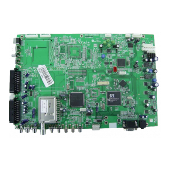
Page 8: Set Apperance
SET APPERANCE INVERTOR(BUILT IN PANEL) MAIN CHASSIS POWER SUPPLY BOARD... -
Page 9: Service Adjustments
LM SERVICE MODE 1. Activating the Service Menu When the menu is on the screen press ‘9’, ‘3’, ’0’, ’1’ on the remote controller. This will activate the service menu. 2. Service Mode Options There are 6 submenus in this mode: OPTIONS0, OPTIONS1, SOUND OPTIONS,IF SETTINGS, DIMMING, ADJUSTMENTS 2.1 OPTIONS0 STANDBY... - Page 10 2.3 SOUND OPTIONS EUROPE, NEWZ (New Zelland) AUST (Australia), NAVAIL (no BG) AVAIL, NAVAIL AVAIL, NAVAIL DOLBY AVAIL, NAVAIL BASS OPT NONE (bass is not activated), DYN (Dinamic bass is activated), SUBW (Subwoofer feature is on) HEADPHONE AVAIL, NAVAIL CARRI MUTE MSP (for all markets except Turkey), MICRO (for Turkey) 2.4 IF SETTINGS TUNER...
- Page 11 MSTAR SPECTRUM 1 ADJUST R GAIN G GAIN B GAIN R OFFSET 125 G OFFSET 125 B OFFSET 126 SUBCON SUB BRI 2.7 EEPROM EDIT No adjustment will be made in this menu for service purposes.
-
Page 12: Block Diagram
Chassis LM Block Diagram Analog Tuner1 TU300 IC335 Analog Tuner2 128MB DDR TU302 IC329 IC328 Flash TxtRAM IC336 Scart1 IC334 94XXA MST6181 Scart2 IC324 IC309 VCTi4993G SVHS TVP150 Video Decoder IR&Key IC321 IC301 IC311 MAX9704 MTV512 Audio Amp. Monitor HDMI YPrPb Controller IC338... -
Page 13: Power Supply Diagram
Power Supply Diagram +12V +3V3 IC300 T300 5V or 12V for LCD Panel MST6181 VCTi IC302 MST3383 DRAM MST3383 IC337 MST6181 VCTi MST6181 IC306 IC305 Only for FRC Audio T300 VCTi, Tuner IC308 VCTi, Switches IC307... -
Page 14: Data Sheet Vct4993
VCT 49xyI, VCT 48xyI ADVANCE INFORMATION Volume 1: General Description General Description – Submicron CMOS technology – Low-power standby mode Release Note: This data sheet describes functions and characteristics of the VCT 49xyI, VCT 48xyI – Single 20.25 MHz reference crystal version F1. -
Page 15: Tint
VCT 49xyI, VCT 48xyI ADVANCE INFORMATION Volume 1: General Description 1.2. Chip Architecture IFIN+ Sound Audio Frontend Processor Demodulator Processor IFIN- 656 out PROT HOUT HFLB VERT Comb Color CVBS in Display & Filter Decoder YCbCr in Video Panorama Video Deflection Frontend Scaler... -
Page 16: Data Sheet Mst6181
MST6181LDA SXGA/WXGA LCD Multi-Function Monitor Controller with Dual LVDS Transmitter Product Brief Version 1.0 FEATURES Ÿ Input supports up to UXGA & 1080P Auto-Configuration/Auto-Detection Ÿ Panel supports up to SXGA/WXGA Ÿ Auto input signal format (SOG, Composite, Ÿ Integrated 8-bit triple-ADC/PLL Separated HSYNC, VSYNC, and DE), and input Ÿ... -
Page 17: General Description
MST6181LDA SXGA/WXGA LCD Multi-Function Monitor Controller with Dual LVDS Transmitter Product Brief Version 1.0 On-Screen OSD Controller Ÿ Supports 2 data output formats: Thine & TI Ÿ 16/256 color palette data mappings Ÿ 256/512 1-bit/pixel font Ÿ Compatible with TIA/EIA Ÿ... - Page 18 MST6181LDA SXGA/WXGA LCD Multi-Function Monitor Controller with Dual LVDS Transmitter Product Brief Version 1.0 PIN DIAGRAM (MST6181LDA) BYPASS DVI_R+ PWM5 Pin 1 DVI_R- PWM4 PWM3 DVI_G+ GPO[6] DVI_G- GPO[5] AVDD_DVI GPO[4] DVI_B+ DVI_B- VDDP DVI_CK+ DVI_CK- VDDC AVDD_DVI GPO[3] GPO[2] REXT AVDD_PLL GPO[1]...
-
Page 19: Pin Description
MST6181LDA SXGA/WXGA LCD Multi-Function Monitor Controller with Dual LVDS Transmitter Product Brief Version 1.0 PIN DESCRIPTION MCU Interface Pin Name Pin Type Function HWRESET Schmitt Trigger Input Hardware Reset, active high w/ 5V-tolerant DBUS[7:0] I/O w/ 5V-tolerant MCU Direct bus; 4mA driving strength 93-86 I w/ 5V-tolerant MCU Bus ALE, active high... - Page 20 MST6181LDA SXGA/WXGA LCD Multi-Function Monitor Controller with Dual LVDS Transmitter Product Brief Version 1.0 Pin Name Pin Type Function BIN1P Analog Input Analog Blue Input from Channel 1 SOGIN1 Analog Input Sync On Green Input from Channel 1 GIN1M Analog Input Reference Ground for Analog Green Input from Channel 1 GIN1P Analog Input...
- Page 21 MST6181LDA SXGA/WXGA LCD Multi-Function Monitor Controller with Dual LVDS Transmitter Product Brief Version 1.0 Pin Name Pin Type Function AUWS Output Word Select Output; 4mA driving strength AUMUTE Output Audio Output Mute Control SPDIFO Output S/PDIF Audio Output; 4mA driving strength AIMCK Input w/ 5V-tolerant Audio Master Clock Input...
- Page 22 MST6181LDA SXGA/WXGA LCD Multi-Function Monitor Controller with Dual LVDS Transmitter Product Brief Version 1.0 GPO Interface Pin Name Pin Type Function PWM0 Output PWM; 4mA driving strength PWM1 Output PWM; 4mA driving strength PWM2 Output PWM; 4mA driving strength PWM3/GPO[7] Output GPO with PWM Function;...
- Page 23 MST6181LDA SXGA/WXGA LCD Multi-Function Monitor Controller with Dual LVDS Transmitter Product Brief Version 1.0 Pin Name Pin Type Function Crystal Oscillator Input XOUT Crystal Oscillator Output Xout Power Pins Pin Name Pin Type Function AVDD_DVI 3.3V Power DVI/HDMI Power 8, 14 AVDD_ADC 3.3V Power ADC Power...
-
Page 24: Data Sheet Mtv512
MTV512M 8051 Embedded Monitor Controller with 64K Flash ROM • Watchdog timer with programmable interval GENERAL DESCRIPTIONS • Support external counters/timers, T0, T1, and ET2 The MTV512M micro-controller is an 8051 CPU core • Single/double frequency clock output embedded device especially tailored for flat panel •... - Page 25 MTV512M PIN CONFIGURATION & DESCRIPTION A “CMOS output pin” means it can sink and drive at least 4mA current. It is not recommended to use such pin as input function. An “open drain pin” means it can sink at least 4mA current. It can be used as input or output function and needs an external pull up resistor.
-
Page 26: Data Sheet Tvp5150A
1 TVP5150A Introduction The TVP5150A device is an ultralow power NTSC/PAL/SECAM video decoder. Available in a space saving 32-pin TQFP package, the TVP5150A decoder converts NTSC, PAL, and SECAM video signals to 8-bit ITU-R BT.656 format. Discrete syncs are also available. The optimized architecture of the TVP5150A decoder allows for ultralow-power consumption. - Page 27 • Fully differential CMOS analog preprocessing channels with clamping and automatic gain control (AGC) for best signal-to-noise (S/N) performance • Ultralow power consumption: 115 mW typical • 32-pin TQFP package • Power-down mode: <1 mW • Brightness, contrast, saturation, hue, and sharpness control through I •...
- Page 28 1.3 Applications The following is a partial list of suggested applications: • Digital television • • Notebook PCs • Cell phones • Video recorder/players • Internet appliances/web pads • Handheld games 1.4 Related Products • TVP5146 NTSC/PAL/SECAM 4x10-Bit Digital Video Decoder With Macrovision Detection, YPbPr/RGB Inputs, 5-Line Comb Filter and SCART/Digital RGB Overlay SupportDecoder With Robust Sync Detector, Literature Number SLES084 1.5 Ordering Information...
- Page 29 1.6 Functional Block Diagram MACROVISION DETECTION LUMINANCE PROCESSING AIP1A AIP1B YOUT[7:0] YCbCr 8-BIT CHROMINANCE 4:2:2 PROCESSING VBI / DATA SLICER I 2 C HOST PROCESSOR INTERFACE XTAL1 FID/GLCO XTAL2 VSYNC/PALI INTERQ/GPCL/VBLK PCLK/SCLK HSYNC AVID Figure 1−1. Functional Block Diagram...
- Page 30 1.7 Terminal Assignments TQFP PACKAGE (TOP VIEW) ZQC PACKAGE (BOTTOM VIEW) 31 30 29 28 27 26 25 AIP1A VSYNC/PALI AIP1B FID/GLCO PLL_AGND PLL_AVDD XTAL1/OSC DVDD XTAL2 DGND AGND YOUT0 RESETB YOUT1 10 11 12 13 14 15 16 1.8 Terminal Functions Table 1−1.
- Page 31 Table 1−1. Terminal Functions (Continued) TERMINAL NUMBER DESCRIPTION DESCRIPTION NAME NAME Analog Section (continued) A/D reference ground. Connect to analog ground through 1-µF capacitor. Also, it is recommended to REFM connect directly to REFP through 1-µF capacitor. Refer to Figure 5−1. REFP A/D reference supply.
-
Page 32: Parts List
PARTS LIST Note: For parts other than those of chassis (cosmetic parts and auxiliary boards like power supply etc) please see the parts lists in the web page. Position Parts code Description Position Parts code Description CAPACITORS C376 294121R CC-CHIP 100NF J 50V /0603 NPO 202476R CC 4.7NF M 250VAC Y5U R:10 C378... - Page 33 Position Parts code Description Position Parts code Description C479 293235R CC-CHIP 22NF J 16V /0603 X7R C602 292153R CC-CHIP 1.5NF K 50V /0603 X7R TAPE C480 293235R CC-CHIP 22NF J 16V /0603 X7R C605 250470R EC 4.7UF 16V 11*5 R:5 C481 293235R CC-CHIP 22NF J 16V /0603 X7R...
- Page 34 IC323 453077R-1 IC-CHIP AT24C32AN-10SU-2.7 (T&R) 102141R CFR 1K J 1/4W /6 26MM IC324 S-SLM512 SW IC LM BEKO VCT4993G-XM 101494R CFR 470R J 1/4W /6 26MM IC325 453529R IC-CHIP MM74HC4066MX SO14 ANALOG SWITCH R8 140472R CFR 47R J 1/4W /3.2 26MM...
- Page 35 Position Parts code Description Position Parts code Description R340 179005R RC-CHIP 0R /0603 1.6*0.8 TAPE R436 179005R RC-CHIP 0R /0603 1.6*0.8 TAPE R342 179005R RC-CHIP 0R /0603 1.6*0.8 TAPE R437 179005R RC-CHIP 0R /0603 1.6*0.8 TAPE R343 179005R RC-CHIP 0R /0603 1.6*0.8 TAPE R442 172473R RC-CHIP 4.7K J 1/10W /0603...
- Page 36 Position Parts code Description Position Parts code Description R535 173100R RC-CHIP 10K J 1/10W /0603 R656 171127R RC-CHIP 120R J 1/16W /0603 TAPE R536 173100R RC-CHIP 10K J 1/10W /0603 R658 171107R RC-CHIP 100R J 1/16W /0603 R537 173100R RC-CHIP 10K J 1/10W /0603 R659 172104R RC-CHIP 1K J 1/16W /0603...
- Page 37 Position Parts code Description Position Parts code Description R795 170225R RC-CHIP 22R J 1/10W /0603 TRANSISTORS R796 170225R RC-CHIP 22R J 1/10W /0603 T102 401141R TRN-CHIP BC848BLT1G SOT23 R797 170225R RC-CHIP 22R J 1/10W /0603 T106 401142R TRN-CHIP BC858BLT1G SOT23 R798 170225R RC-CHIP 22R J 1/10W /0603...