Toro Power Max 726 OE Operator's Manual
Snowthrower
Hide thumbs
Also See for Power Max 726 OE:
- Operator's manual (28 pages) ,
- Operator's manual (32 pages) ,
- Operator's manual (32 pages)
Table of Contents
Advertisement
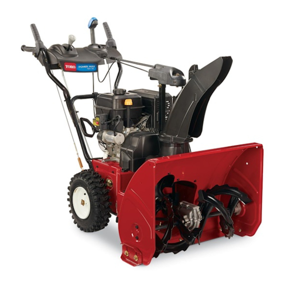
Power Max 726/826 OE Snowthrower
Model No. 37771-Serial No. 313000001 and Up
Model No. 37772-Serial No. 313000001 and Up
Introduction
This machine is intended to be used by residential
homeowners or professional, hired operators. It is
designed for removing snow from paved surfaces, such
as driveways and sidewalks, and other surfaces for
traffic on residential or commercial properties. It is not
designed for removing materials other than snow, nor is
a model with a pivoting scraper designed for clearing off
gravel surfaces.
Read this information carefully to learn how to operate and
maintain your machine properly and to avoid injury and
machine damage. You are responsible for operating the
machine properly and safely.
You may contact Toro directly at www.Toro.com for machine
and accessory information, help finding a dealer, or to register
your machine.
Whenever you need service, genuine Toro parts, or additional
information, contact an Authorized Service Dealer or Toro
Customer Service and have the model and serial numbers of
your machine ready. Figure 1 identifies the location of the
model and serial numbers on the machine. Write the numbers
in the space provided.
g018884
1. Model and serial number location
Model No.
Serial No.
This manual identifies potential hazards and has safety
messages identified by the safety alert symbol (Figure 2),
© 2012-The Toro® Company
8111 Lyndale Avenue South
Bloomington, MN 55420
Figure 1
Register at www.Toro.com.
which signals a hazard that may cause serious injury or death
if you do not follow the recommended precautions.
1. Safety alert symbol
This manual uses 2 words to highlight information.
Important calls attention to special mechanical information
and Note emphasizes general information worthy of special
attention.
WARNING
CALIFORNIA
Proposition 65 Warning
The engine exhaust from this product
contains chemicals known to the State of
California to cause cancer, birth defects,
or other reproductive harm.
This spark ignition system complies with Canadian ICES-002.
The enclosed Engine Owner's Manual is supplied for
information regarding the US Environmental Protection
Agency (EPA) and the California Emission Control
Regulation of emission systems, maintenance, and
warranty. Replacements may be ordered through the
engine manufacturer.
Contents
Introduction .................................................................. 1
Training ................................................................. 3
Preparation............................................................. 3
Operation............................................................... 3
Clearing a Clogged Discharge Chute .......................... 4
Maintenance and Storage.......................................... 4
Toro Snowthrower Safety ......................................... 4
Safety and Instructional Decals ................................. 5
Setup ............................................................................ 7
1 Installing the Upper Handle.................................... 8
Original Instructions (EN)
All Rights Reserved *3374-192* A
Printed in the USA
Form No. 3374-192 Rev A
Operator's Manual
Figure 2
Advertisement
Table of Contents

Related Manuals for Toro Power Max 726 OE


Summary of Contents for Toro Power Max 726 OE
-
Page 1: Table Of Contents
Note emphasizes general information worthy of special machine damage. You are responsible for operating the attention. machine properly and safely. You may contact Toro directly at www.Toro.com for machine WARNING and accessory information, help finding a dealer, or to register your machine. - Page 2 2 Installing the Traction Control Linkage ....8 Maintenance ..............19 3 Installing the Chute ..........9 Recommended Maintenance Schedule(s) ......19 4 Installing the Chute Control Rod ......9 Preparing for Maintenance........19 5 Filling the Engine with Oil........10 Checking the Engine Oil Level .........19 6 Checking the Tire Pressure ........11 Checking and Adjusting the Skids and 7 Checking the Skids and Scraper ......11...
-
Page 3: Training
Training eyes from foreign objects that may be thrown from the machine. • Read, understand and follow all instructions on the machine and in the manual(s) before operating this Operation machine. Be thoroughly familiar with the controls and the proper use of the machine. Know how to stop the •... -
Page 4: Clearing A Clogged Discharge Chute
Run the machine a few minutes after throwing snow to prevent freeze-up of the rotor blades. Toro Snowthrower Safety The following list contains safety information specific to Toro machines or other safety information that you must know. • Rotating auger/impeller can cut off or injure fingers or hands. -
Page 5: Safety And Instructional Decals
Safety and Instructional Decals Important: Safety and instruction decals are located near areas of potential danger. Replace damaged decals. 121–6817 1. Cutting dismemberment, impeller and cutting dismemberment, auger hazards—keep bystanders a safe distance from the snowthrower. 121–6823 1. Fast 3. Slow 2. - Page 6 Briggs & Stratton Part No. 273676 3. Fast 1. Stop 2. Slow Briggs & Stratton Part No. 277588 1. Primer 3. Ignition key out Briggs & Stratton Part No. 275949 (Engine—Stop) 1. Choke on (Choke) 2. Choke off (Run) 2. Ignition key in (Engine—Run) Briggs &...
-
Page 7: Setup
Setup Loose Parts Use the chart below to verify that all parts have been shipped. Procedure Description Qty. Handle bolts Curved washers Install the upper handle. Locknuts – No parts required Install the traction control linkage. Install the chute. Bolt Carriage bolts Install the chute control rod. -
Page 8: Installing The Upper Handle
Installing the Upper Handle Parts needed for this procedure: Handle bolts Curved washers g019004 Locknuts Figure 4 Procedure 2. Secure the lower end of the speed control rod with the 1. Lift and rotate the upper handle and position it over washer and hairpin cotter that you previously removed. -
Page 9: Installing The Chute
Note: If the trunnion does not fit into the hole when you lift up on the speed control rod, rotate the trunnion upward or downward on the speed control rod until it fits. 7. Secure the trunnion and upper end of the speed control rod with the outer washer and a hairpin cotter you previously removed. -
Page 10: Filling The Engine With Oil
Figure 11 1. Cable clip 2. Deflector cable Figure 9 1. Short rod 2. Long chute control rod 7. Hold the blue trigger cap down and rotate the Quick Stick in a circle to ensure that the chute and deflector operate smoothly. -
Page 11: Checking The Tire Pressure
Engine Oil Capacities (cont'd.) Model Engine Oil Capacity 37771 18 to 20 oz. (0.53 to 0.59 l) Checking the Skids and 37772 Scraper 1. Remove the dipstick and slowly pour oil into the oil fill tube to raise the oil level to the Full mark on the dipstick. -
Page 12: Product Overview
Product Overview Figure 14 The machine should move rearward. If the machine does not move or moves forward, complete the following: A. Release the traction lever and stop the engine. B. Disconnect the trunnion from the speed selector g018887 lever (Figure 5). C. -
Page 13: Operation
Filling the Fuel Tank DANGER Gasoline is extremely flammable and explosive. A Figure 17 fire or explosion from gasoline can burn you and 1. Snow cleanout tool (attached to the handle) others. • To prevent a static charge from igniting the gasoline, place the container and/or machine Operation on the ground before filling, not in a vehicle or... -
Page 14: Starting The Engine
Starting the Engine 1. Check the engine oil level. Refer to Checking the Engine Oil Level in Maintenance. 2. Turn the fuel shutoff valve 1/4 turn counterclockwise to open it (Figure 21). Figure 21 g018889 Figure 20 1. 1-1/2 inch (3.8 cm) 3. - Page 15 4. Firmly push in the primer with your thumb 2 times 7. Start the machine pulling the recoil starter or pressing (15°F or -9°C or above) or 4 times (below 15°F or the electric-starter button (Figure 26). -9°C), holding the primer in for a second before releasing it each time (Figure 23).
-
Page 16: Stopping The Engine
Operating the Traction Drive CAUTION If you leave the machine plugged into a CAUTION power outlet, someone can inadvertently start the machine and injure people or damage If the traction drive is not properly adjusted, the property. machine may move in the direction opposite of what you intended, causing injury and/or property Unplug the power cord whenever you are not damage. -
Page 17: Operating The Auger/Impeller Drive
Operating the Auger/Impeller Drive 1. To engage the auger/ impeller drive, squeeze the right hand (auger/ impeller) lever to the handgrip (Figure 31). Figure 32 Moving the Discharge Chute Figure 31 Hold the blue trigger cap down and move the Quick Stick to the left to move the discharge chute to the left;... -
Page 18: Unclogging The Discharge Chute
from freezing. Stop the engine, wait for all moving parts to stop, and remove all ice and snow from the machine. • With the engine off, pull the recoil starter handle several times and push the electric-starter button once to prevent the recoil and electric starters from freezing up. -
Page 19: Maintenance
• Have an Authorized Service Dealer inspect and replace the traction drive belt and/or the auger/impeller drive belt, if necessary. Important: You can find more information about maintaining and servicing your machine at www.Toro.com. Important: Refer to your engine operator's manual for additional maintenance procedures. For engine adjustments, repairs, or warranty service not covered in this manual, contact an Authorized Briggs &... -
Page 20: Checking And Adjusting The Traction Cable
Check the skids and the scraper to ensure that the auger does If the left hand (traction) cable is not properly adjusted, do not contact the paved or gravel surface. Adjust the skids and the following steps: the scraper as needed to compensate for wear. 1. -
Page 21: Checking The Auger Gearbox Oil Level
Yearly—Inspect the auger/impeller cable and adjust or replace it if necessary. 1. Loosen the jam nut. 2. Engage the auger/impeller lever and hold it in place (Figure 39). Figure 41 3. Remove the pipe plug from the gearbox. Figure 39 4. -
Page 22: Changing The Engine Oil
Changing the Engine Oil 5. Fill the crankcase with oil. Refer to Filling the Engine Crankcase with Oil. Service Interval: After the first 5 hours—Change the engine oil. Lubricating the Hex Shaft Every 25 hours/Yearly (whichever comes first)—Change the engine oil. Service Interval: Yearly—Lubricate the hex shaft. -
Page 23: Replacing The Spark Plug
6. Move the speed selector lever to Position 6. 7. Lubricate the other end of the hex shaft. 8. Move the speed selector lever forward and rearward a few times. 9. Install the back cover and return the machine to the operating position. -
Page 24: Adjusting The Discharge Chute Latch
Adjusting the Discharge Chute Storage Latch WARNING If the discharge chute does not lock into the desired position or does not unlock so that you can move it to another • Gasoline vapors can explode. position, adjust the discharge chute latch. •... -
Page 25: Troubleshooting
Troubleshooting Problem Possible Cause Corrective Action Electric starter does not turn (electric-start 1. The power cord is disconnected at the 1. Connect the power cord to the outlet models only) outlet or the machine. and/or the machine. 2. The power cord is worn, corroded, or 2. - Page 26 5. Unclog the discharge chute. 6. The auger/impeller drive belt is loose 6. Install and/or adjust the auger/impeller or is off the pulley. drive belt; refer to www.Toro.com for servicing information or take the machine to an Authorized Service Dealer.
- Page 27 Notes:...
- Page 28 Notes:...
- Page 29 Notes:...
- Page 30 Such use will not reduce the warranty obligations of The Toro Company. 10. Add-on or modified parts that are not approved by The Toro Company may not be used. The use of a non-approved add-on or modified parts by the purchaser will be grounds for disallowing a warranty claim.
- Page 31 1. Fuel System Parts • Carburetor and internal parts • Cold starting enrichment (primer or choke) • Fuel pump • Fuel line, fittings, and clamps • Fuel tank, cap, and tether • Carbon canister 2. Air Induction System • Air cleaner •...
- Page 32 Countries Other than the United States or Canada Customers who have purchased Toro products exported from the United States or Canada should contact their Toro Distributor (Dealer) to obtain guarantee policies for your country, province, or state. If for any reason you are dissatisfied with your Distributor's service or have difficulty obtaining guarantee information, contact the Toro importer.