
Related Manuals for Beko DRYPOINT RA 20-960


Summary of Contents for Beko DRYPOINT RA 20-960
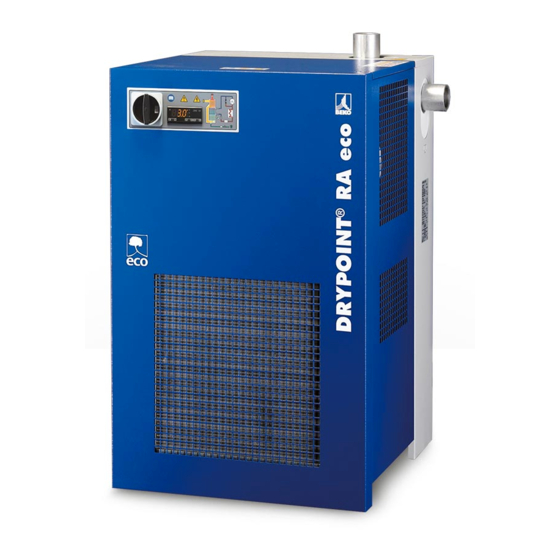
- Page 1 EN - english Instructions for installation and operation Compressed air refrigeration dryer ® DRYPOINT RA 20-960...
-
Page 2: Electric Diagram Drypoint Ra 330-960 3Phase Sheet
Dear customer, ® Thank you for deciding in favour of the DRYPOINT RA 20-960 compressed-air refrigeration dryer. Please read these ® installation and operating instructions carefully before mounting and starting up the DRYPOINT RA 20-960 and follow ® our directions. Perfect functioning of the DRYPOINT RA 20-960 and thus reliable compressed-air drying can only be guaranteed when the provisions and notes stipulated here are strictly adhered to. -
Page 3: Table Of Contents
Contents Name plate Safety instructions Safety pictograms in accordance with DIN 4844 Signal words in accordance with ANSI Overview of the safety instructions Proper use Exclusion from a field of application ... - Page 4 13.3.7 Electric diagram DRYPOINT RA 330-960 3phase Sheet 2/3 13.3.8 Electric diagram DRYPOINT RA 330-960 3phase Sheet 3/3 EC Declaration of Conformity Pos: 1 /Beko Technische Dokumentation/Überschriften/1/Sicherheitshinweise @ 0\mod_1183637609261_6.doc @ 5365 DRYPOINT® RA 20-960...
-
Page 5: Name Plate
This manual must be available at all times for future reference and is a constituent part of the dryer. If you have any queries regarding these installation and operating instructions, please contact BEKO TECHNOLOGIES GMBH. -
Page 6: Safety Pictograms In Accordance With Din 4844
Do not operate with open cover (housing) Maintenance works or controlling measures must only be carried out by qualified personnel Do not smoke Note Pos: 4 /Beko Technische Dokumentation/Sicherheit/Gefahr Druckluft @ 0\mod_1184148143854_6.doc @ 577 ARIA Connection point compressed-air inlet LUFT... - Page 7 Safety instructions Works can be carried out by the operator of the plant, provided that they are skilled accordingly NOTE: Text that contains important specifications to be considered – does not refer to safety precautions. The device was carefully designed with particular attention paid to environmental protection: ...
-
Page 8: Signal Words In Accordance With Ansi
Make sure that the power supply is switched off and that the device is off and marked for maintenance measures. Please also ensure that the power supply cannot be re-established during the works. Pos: 7 /Beko Technische Dokumentation/Sicherheit/Maßnahmen Netzspannung BM 31/32/33 @ 0\mod_1216898430699_6.doc @ 11319 Caution! Refrigerant! The compressed-air refrigeration dryer uses HFC-containing refrigerants as a coolant. - Page 9 Safety instructions Warning! Refrigerant leak! A refrigerant leak involves the danger of serious injury and damage to the environment. ® The DRYPOINT RA 20-960 compressed-air refrigeration dryer contains fluorinated greenhouse gas/refrigerant. Installation, repair and maintenance works at the refrigeration system must only be carried out by certified skilled personnel (specialists).
- Page 10 Operators of the devices must observe the local and national pressure equipment regulations in the country of installation. Pos: 8 /Beko Technische Dokumentation/Sicherheit/Sicherheitshinweise, weitere BM (nicht Ex) @ 0\mod_1183616103770_6.doc @ 4009os: 9 /Beko Technische Dokumentation/Sicherheit/Zusatz Sicherheitshinweise BM33 @ 0\mod_1231926887620_6.doc @ 12829s: 10 /Beko Technische Dokumentation/Sicherheit/Vorsicht Fehlfunktion @ 0\mod_1214378096290_6.doc @ 9359 Note!
-
Page 11: Proper Use
Pos: 15 /Beko Technische Dokumentation/Übeschriften/1/Ausschluss vom Anwendungsbereich @ 0\mod_1236003439359_6.doc @ 13709 Exclusion from a field of application Pos: 16 /Beko Technische Dokumentation/Bestimmungsgemäße Verwendung/BEKOMAT/Ausschluß Anwendung BM 31/32/33 @ 0\mod_1236003837511_6.doc @ 13736 Note! Improper use! The device is intended for the separation of water in compressed air. -
Page 12: Operating Instructions In Accordance With The 97/23/Ec Pressure Equipment Directive
Operating instructions in accordance with the 97/23/EC Pressure Equipment Directive Operating instructions in accordance with the 97/23/EC Pressure Equipment Directive The DRYPOINT® RA 20-960 compressed-air refrigeration dryer contains pressure equipment in the sense of the 97/23/EC Pressure Equipment Directive. Therefore, the entire plant needs to be registered with the supervisory authority if required in accordance with the local regulations. -
Page 13: Transport
Transport Transport Check the packaging for visible loss or damage. If no visible damage can be ascertained, place the unit in close proximity to the place of installation and unpack the device. During this procedure, the dryer must always remain in an upright position. The components may be damaged when the unit is tilted or turned upside down. -
Page 14: Installation
Installation Installation Place of installation Note! Ambient conditions! In the event that the dryer is not installed under suitable ambient conditions, the ability of the device to condense refrigerant gas is impaired. This can result in a higher load of the refrigerating compressor, and in a loss of efficiency and performance of the dryer. -
Page 15: Installation Plan
Installation Installation plan - A - Air compressor Aftercooler Condensate separator Prefilter Bypass group Dryer Compressed-air tank - B - Final filter Bekomat condensate drain Installation type A is recommended when the total consumption corresponds to the throughput rate of the compressor. Installation type B is recommended when the air consumption constantly varies, with peak values which considerably exceed the throughput rate of the compressor. -
Page 16: Correction Factors
Installation Correction factors Correction factor for operating pressure modifications: Air inlet pressure bar(g) Factor (F1) 0.77 0.86 0.93 1.00 1.05 1.14 1.21 1.27 Correction factor for ambient temperature modifications (air cooling): Ambient temperature ºC Factor (F2) 1.00 0.96 0.91 0.85 0.76 0.64 Correction factor for air inlet temperature modifications:... -
Page 17: Connection To The Compressed-Air System
Installation Connection to the compressed-air system Danger! Compressed air! All works must only be carried out by qualified skilled personnel. Never work on compressed-air systems which are under pressure. The operator or the user must ensure that the dryer is never operated with a pressure exceeding the maximum pressure value indicated on the name plate. -
Page 18: Minimum Cooling Water Requirements
Installation Minimum cooling water requirements: 15 … 30°C (1) / SO >1.0 mg/l or ppm Temperature Pressure 3…10 bar(g) (2) <2 mg/l or ppm Delivery pressure > 3 bar (2) (3) 50 mg/l or ppm Total hardness 6.0…15 dH° 0.5 mg/l or ppm 7.5…9.0 <0.05 mg/l or ppm Conductivity... -
Page 19: Electrical Connections
Installation Electrical connections Danger! Supply voltage! The connection to the electric mains should only be carried out by qualified skilled personnel and must correspond to the legal provisions in force in your region. Prior to connecting the device, please check the name plate to avoid exceeding the indicated values. The voltage tolerance is +/- 10%. -
Page 20: Start-Up
Start-up Start-up Preliminary stages Note! Exceeding of the operating parameters! Ensure that the operating parameters comply with the nominal values indicated on the name plate of the dryer (voltage, frequency, air pressure, air temperature, ambient temperature etc.). Prior to delivery, this dryer was thoroughly tested, packed and checked. Please verify the soundness of the dryer during the initial start-up and check the perfect functioning during the first operating hours. -
Page 21: Shut Down And Restart
Start-up Note! A dew point between 0°C and +10°C displayed on the DMC 18 control unit is considered to be correct according to the possible operating conditions (flow rate, air inlet temperature, ambient temperature etc.). During the operation, the refrigerating compressor runs continuously. The dryer needs to be switched on during the entire compressed-air usage time, even if the compressed-air compressor works periodically. -
Page 22: Technical Data
Technical data 10 Technical data 10.1 Technical data DRYPOINT RA 20-110 1/230/50-60 DRYPOINT® RA 20-960... -
Page 23: Technical Data Drypoint Ra 135-960 1/230/50
Technical data 10.2 Technical data DRYPOINT RA 135-960 1/230/50 DRYPOINT® RA 20-960... -
Page 24: Technical Data Drypoint Ra 330-960 3Phase 3/400/50
Technical data 10.3 Technical data DRYPOINT RA 330-960 3phase 3/400/50 DRYPOINT® RA 20-960... -
Page 25: Technical Data Drypoint Ra 20-330 1/115/60
Technical data 10.4 Technical data DRYPOINT RA 20-330 1/115/60 DRYPOINT® RA 20-960... -
Page 26: Technical Data Drypoint Ra 135-960 1/230/60
Technical data 10.5 Technical data DRYPOINT RA 135-960 1/230/60 DRYPOINT® RA 20-960... -
Page 27: Technical Data Drypoint Ra 330-960 3Phase 3/460/60
Technical data 10.6 Technical data DRYPOINT RA 330-960 3phase 3/460/60 DRYPOINT® RA 20-960... -
Page 28: Technical Description
Technical description 11 Technical description 11.1 Control panel The control panel explained below is the only dryer user interface. RA 20 – 240 RA 330 – 960 Main switch Electronic control unit DMC 18 Air and refrigerant gas flow chart RA 330 –... -
Page 29: Flow Chart (Air-Cooled)
Technical description 11.3 Flow chart (air-cooled) P< P> 11.4 Flow chart (water-cooled) P< P> Aluminium heat exchanger module Condenser fan (air cooled) a – Air/air heat exchanger Filter dryer b – Air/refrigerant heat exchanger Capillary tube c – Condensate separator T1 temperature sensor (dew point) Refrigerant pressure switch LPS (P<) Condensate drain shut-off valve... -
Page 30: Refrigerating Compressor
Technical description 11.5 Refrigerating compressor The employed refrigerating compressors are constructed by leading manufacturers. The hermetically sealed construction is absolutely gastight. The integrated safeguard protects the compressor against overheating and excess current. The protection is automatically reset as soon as the nominal conditions are reached again. 11.6 Condenser (air-cooled) The condenser is the component in which the gas coming from the compressor is cooled down, condensed and liquefied. -
Page 31: Refrigerant Pressure Switches Lps - Hps - Pv
Technical description 11.13 Refrigerant pressure switches LPS – HPS – PV To ensure the operational reliability and the protection of the dryer, a series of pressure switches are installed in the gas cycle. LPS : Low-pressure guard on the suction side of the compressor, which is triggered when the pressure drops below the predetermined value. -
Page 32: Dmc 18 Electronics (Control Unit Compressed-Air Dryer)
Technical description 11.16 DMC 18 electronics (control unit compressed-air dryer) Led - temperature in °C Led - temperature in °F Led – drain ON Led – alarm/service Button – access configuration menu Button – decrease / service Button – increase / drain test DISPLAY The DMC18 controls the alarms and the settings of the dryer operation and of the BEKOMAT drain. -
Page 33: Operation Of The Potential-Free Failure/Alarm Contact
Technical description 11.16.5 Operation of the potential-free failure/alarm contact The DMC 18 is equipped with a potential-free contact to indicate failures or alarm conditions. Dryer is switched on and no service warning/alarm is active. Dryer is off or a service warning/alarm is active. 11.16.6 How to change operating parameters –... -
Page 34: Electronically Level-Controlled Bekomat Condensate Drain
Technical description 11.17 Electronically level-controlled BEKOMAT condensate drain The electronically level-controlled BEKOMAT condensate drain boasts a special condensate management which ensures that condensate is discharged safely and without an unnecessary loss of compressed air. This drain has a condensate collection container in which a capacitive sensor continuously monitors the liquid level. As soon as the switching level is reached, the capacitive sensor transmits a signal to the electronic control and a membrane solenoid valve opens to discharge the condensate. -
Page 35: Maintenance, Troubleshooting, Spare Parts And Dismantling
Maintenance, troubleshooting, spare parts and dismantling 12 Maintenance, troubleshooting, spare parts and dismantling 12.1 Checks and maintenance Certified skilled personnel Installation works must exclusively be carried out by authorised and qualified skilled personnel. Prior to ® undertaking any measures on the DRYPOINT RA 20-960 compressed-air refrigeration dryer, the certified skilled personnel shall read up on the device by carefully studying the operating instructions. -
Page 36: Troubleshooting
Maintenance, troubleshooting, spare parts and dismantling DAILY: • Check whether the dew point indicated on the electronics is correct. • Ensure that the condensate drain system functions properly. • Make sure that the condenser is clean. EVERY 200 HOURS OR MONTHLY •... - Page 37 The dryer does not discharge the condensate – see the corresponding point. The hot-gas bypass valve needs to be re-adjusted – contact a BEKO service technician to have the nominal setting re-established. There is a leak in the refrigeration cycle – contact a BEKO service technician.
- Page 38 8. The adjusting valve for the cooling-water flow needs to be re-adjusted – contact a specialist to have the nominal calibration re-established (water-cooled). 9. There is a leak in the refrigeration cycle – please contact a BEKO service technician. ...
-
Page 39: Recommended Spare Parts
Maintenance, troubleshooting, spare parts and dismantling 12.3 Recommended spare parts NOTE: To order the recommended spare parts or other elements, the data on the name plate must be indicated. DRYPOINT® RA 20-960... - Page 40 Maintenance, troubleshooting, spare parts and dismantling DRYPOINT® RA 20-960...
- Page 41 Maintenance, troubleshooting, spare parts and dismantling DRYPOINT® RA 20-960...
- Page 42 Maintenance, troubleshooting, spare parts and dismantling DRYPOINT® RA 20-960...
-
Page 43: Maintenance Works At The Refrigeration Cycle
When delivered, the dryer is ready to operate and filled with a refrigerant of the R134a or R407C type. Should you detect a refrigerant leak, please contact a BEKO service technician. Prior to any intervention, the room needs to be ventilated. -
Page 44: Appendices
Appendices 13 Appendices 13.1 Dryer dimensions 13.1.1 Dryer dimensions DRYPOINT RA 20-70 DRYPOINT® RA 20-960... -
Page 45: Dryer Dimensions Drypoint Ra 110-135
Appendices 13.1.2 Dryer dimensions DRYPOINT RA 110-135 DRYPOINT® RA 20-960... -
Page 46: Dryer Dimensions Drypoint Ra 190-240
Appendices 13.1.3 Dryer dimensions DRYPOINT RA 190-240 DRYPOINT® RA 20-960... -
Page 47: Dryer Dimensions Drypoint Ra 330-370
Appendices 13.1.4 Dryer dimensions DRYPOINT RA 330-370 DRYPOINT® RA 20-960... -
Page 48: Dryer Dimensions Drypoint Ra 490-630
Appendices 13.1.5 Dryer dimensions DRYPOINT RA 490-630 DRYPOINT® RA 20-960... -
Page 49: Dryer Dimensions Drypoint Ra 750-960
Appendices 13.1.6 Dryer dimensions DRYPOINT RA 750-960 DRYPOINT® RA 20-960... -
Page 50: Dryer Dimensions Drypoint Ra 330-370 3Phase
Appendices 13.1.7 Dryer dimensions DRYPOINT RA 330-370 3phase DRYPOINT® RA 20-960... -
Page 51: Dryer Dimensions Drypoint Ra 490-630 3Phase
Appendices 13.1.8 Dryer dimensions DRYPOINT RA 490-630 3phase DRYPOINT® RA 20-960... -
Page 52: Dryer Dimensions Drypoint Ra 750-960 3Phase
Appendices 13.1.9 Dryer dimensions DRYPOINT RA 750-960 3phase DRYPOINT® RA 20-960... -
Page 53: Exploded Diagrams
Appendices 13.2 Exploded diagrams 13.2.1 Components of the exploded diagrams Alu drying module 20 Refrigerant reservoir (water-cooled) 1.1 Insulation material 21 Bekomat drain Refrigerant pressure switch LPS 22 Main switch Safety temperature switch TS … Refrigerant pressure switch HPS 51 Front panel Refrigerant fan pressure switch PV 52 Back plate Compressor... -
Page 54: Exploded Diagram Drypoint Ra 20-70 /Ac
Appendices 13.2.2 Exploded diagram DRYPOINT RA 20-70 /AC DRYPOINT® RA 20-960... -
Page 55: Exploded Diagram Drypoint Ra 110-135 /Ac
Appendices 13.2.3 Exploded diagram DRYPOINT RA 110-135 /AC DRYPOINT® RA 20-960... -
Page 56: Exploded Diagram Drypoint Ra 190-240 /Ac
Appendices 13.2.4 Exploded diagram DRYPOINT RA 190-240 /AC DRYPOINT® RA 20-960... -
Page 57: Exploded Diagram Drypoint Ra 330-370 /Ac
Appendices 13.2.5 Exploded diagram DRYPOINT RA 330-370 /AC DRYPOINT® RA 20-960... -
Page 58: Exploded Diagram Drypoint Ra 490-630 /Ac
Appendices 13.2.6 Exploded diagram DRYPOINT RA 490-630 /AC DRYPOINT® RA 20-960... -
Page 59: Exploded Diagram Drypoint Ra 750-960 /Ac
Appendices 13.2.7 Exploded diagram DRYPOINT RA 750-960 /AC DRYPOINT® RA 20-960... -
Page 60: Exploded Diagram Drypoint Ra 330-370 /Wc
Appendices 13.2.8 Exploded diagram DRYPOINT RA 330-370 /WC DRYPOINT® RA 20-960... -
Page 61: Exploded Diagram Drypoint Ra 490-630 /Wc
Appendices 13.2.9 Exploded diagram DRYPOINT RA 490-630 /WC DRYPOINT® RA 20-960... -
Page 62: Exploded Diagram Drypoint Ra 750-960 /Wc
Appendices 13.2.10 Exploded diagram DRYPOINT RA 750-960 /WC DRYPOINT® RA 20-960... -
Page 63: Exploded Diagram Drypoint Ra 330-370 3Phase /Ac
Appendices 13.2.11 Exploded diagram DRYPOINT RA 330-370 3phase /AC DRYPOINT® RA 20-960... -
Page 64: Exploded Diagram Drypoint Ra 490-630 3Phase /Ac
Appendices 13.2.12 Exploded diagram DRYPOINT RA 490-630 3phase /AC DRYPOINT® RA 20-960... -
Page 65: Exploded Diagram Drypoint Ra 750-960 3Phase /Ac
Appendices 13.2.13 Exploded diagram DRYPOINT RA 750-960 3phase /AC DRYPOINT® RA 20-960... -
Page 66: Exploded Diagram Drypoint Ra 330-370 3Phase /Wc
Appendices 13.2.14 Exploded diagram DRYPOINT RA 330-370 3phase /WC DRYPOINT® RA 20-960... -
Page 67: Exploded Diagram Drypoint Ra 490-630 3Phase /Wc
Appendices 13.2.15 Exploded diagram DRYPOINT RA 490-630 3phase /WC DRYPOINT® RA 20-960... -
Page 68: Exploded Diagram Drypoint Ra 750-960 3Phase /Wc
Appendices 13.2.16 Exploded diagram DRYPOINT RA 750-960 3phase /WC DRYPOINT® RA 20-960... -
Page 69: Electric Diagrams
Appendices 13.3 Electric diagrams 13.3.1 Electric diagrams – list of components Compressor Compressor thermal protection Compressor starting relay (if installed) Compressor starting capacitor (if installed) Compressor operating capacitor (if installed) Condenser fan Fan starting capacitor (if installed) DMC18 DMC18 electronic instrument – air dryer control T1 Temperature probe –... -
Page 70: Electric Diagram Drypoint Ra 20-135
Appendices 13.3.2 Electric diagram DRYPOINT RA 20-135 DRYPOINT® RA 20-960... -
Page 71: Electric Diagram Drypoint Ra 190-240
Appendices 13.3.3 Electric diagram DRYPOINT RA 190-240 DRYPOINT® RA 20-960... -
Page 72: Electric Diagram Drypoint Ra 330-370
Appendices 13.3.4 Electric diagram DRYPOINT RA 330-370 DRYPOINT® RA 20-960... -
Page 73: Electric Diagram Drypoint Ra 490-960
Appendices 13.3.5 Electric diagram DRYPOINT RA 490-960 DRYPOINT® RA 20-960... -
Page 74: Electric Diagram Drypoint Ra 330-960 3Phase Sheet
Appendices 13.3.6 Electric diagram DRYPOINT RA 330-960 3phase Sheet 1/3 DRYPOINT® RA 20-960... -
Page 75: Electric Diagram Drypoint Ra 330-960 3Phase Sheet 2/3
Appendices 13.3.7 Electric diagram DRYPOINT RA 330-960 3phase Sheet 2/3 DRYPOINT® RA 20-960... -
Page 76: Electric Diagram Drypoint Ra 330-960 3Phase Sheet
Appendices 13.3.8 Electric diagram DRYPOINT RA 330-960 3phase Sheet 3/3 DRYPOINT® RA 20-960... - Page 77 Appendices DRYPOINT® RA 20-960...
- Page 78 Appendices DRYPOINT® RA 20-960...
-
Page 79: Ec Declaration Of Conformity
EC Declaration of Conformity 14 EC Declaration of Conformity DRYPOINT® RA 20-960... - Page 80 EC Declaration of Conformity DRYPOINT® RA 20-960...
- Page 81 EC Declaration of Conformity DRYPOINT® RA 20-960...
- Page 82 EC Declaration of Conformity DRYPOINT® RA 20-960...
- Page 83 Hot-gas bypass valve ......... 30 A I Advice, safety instructions ........5 Appendices ............44 Initial start-up ............20 Installation ............14 B Installation plan ........... 15 BEKOMAT ............34 M C Maintenance ............35 Capillary tube ............30 Maintenance works at the refrigeration cycle ..43 Certified skilled personnel ......
- Page 84 Phone: +81 44 328 76 01 info@beko-technologies.co.jp Benelux Polska / Poland Scandinavia BEKO TECHNOLOGIES B.V. BEKO TECHNOLOGIES Sp. z o.o. BEKO TECHNOLOGIES AB Veenen 12 ul. Chłapowskiego 47 Industrivägen 39 NL - 4703 RB Roosendaal PL-02-787 Warszawa S-43361 Sävedalen...