Table of Contents
Advertisement
The service manual for this product includes Pioneer's RRV1898 PD-F907/KU service manual. The
pages preceding that manual list additional specifications, all service changes between Pioneer's
RRV1898 PD-F907/KU and the 42-5064 CD8400, and any RadioShack part numbers that are different
from the Pioneer part numbers.
The specifications on Page 51 of the RRV1898 service manual for Pioneer's model PD-F907/KU are
like the specifications listed in the owner's manual for the 42-5064 CD-8400. Additional specs are
given on the page inside the back cover.
Optimus and Radio Shack are registered trademarks used by Tandy Corporation.
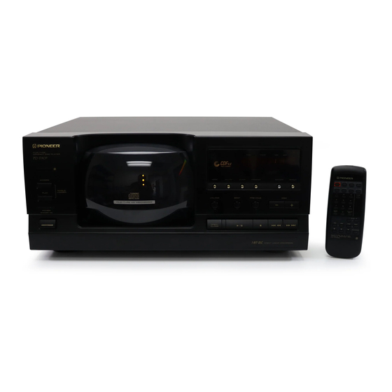
MODEL CD-8400
FILE-TYPE CD PLAYER
Catalog Number: 42-5064
©
1998 Tandy Corporation.
All Rights Reserved.
Advertisement
Table of Contents

Related Manuals for Pioneer CD-8400


Summary of Contents for Pioneer CD-8400
- Page 1 ¶ The specifications on Page 51 of the RRV1898 service manual for Pioneer's model PD-F907/KU are like the specifications listed in the owner's manual for the 42-5064 CD-8400. Additional specs are given on the page inside the back cover. ©...
- Page 2 Be sure to replace only with specified parts. ÷ Ref. No. : Numbers following P and hyphen(–) indicate the page(s) and location number(s) in the RRV1898 service manual, respectively. 42-5064 CD-8400 and PD-F907/KU are constructed the same except for the following: Parts No. Ref.No. Mark...
-
Page 3: Table Of Contents
Service FILE–TYPE COMPACT DISC PLAYER DISC TRACK PD-F905 Manual Î ACSESS TITLE TITLE MODE HI-LITE CLEAR PROGRAM INPUT DISPLAY SINGLE LOADER PLAY UNLOAD BEST PREVIOUS DISC FILE –TYME CD MECHANISM ORDER NO. OPEN/ CLOSE RRV1898 FILE-TYPE CD PLAYER PD-F957 PD-F907 THIS MANUAL IS APPLICABLE TO THE FOLLOWING MODEL(S) AND TYPE(S). -
Page 4: Safety Information
PD-F957,PD-F907 1. SAFETY INFORMATION This service manual is intended for qualified service technicians; it is not meant for the casual do-it-yourselfer. Qualified technicians have the necessary test equipment and tools, and have been trained to properly and safely repair complex products such as those covered by this manual. Improperly performed repairs can adversely affect the safety and reliability of the product and may void the warranty. -
Page 5: Exploded Views And Parts List
PD-F957,PD-F907 2. EXPLODED VIEWS AND PARTS LIST NOTES : ÷ Parts marked by “ NSP ” are generally unavailable because they are not in our Master Spare Parts List. ÷ The mark found on some component parts indicates the importance of the safety factor of the part. Therefore, when replacing, be sure to use parts of identical designation. - Page 6 PD-F957,PD-F907 2.2 EXTERIOR KU/CA,KU type only PD-F907 only PD-F907 only...
- Page 7 PD-F957,PD-F907 65 6 Refer to 32(3/4) ''2.3 LOADING MECHANISM 32(4/4) ASSY'' Note1 32(2/4) 21(1/2) 32(1/4) Note1 21 (2/2) Note2 21(1/2) 26(2/2) 26(1/2) Note1 cutting position Note2 cutting position No.21(Back Fence) cutting No.26(Hood Base) 26(2/2) 21(2/2) cutting cutting 21(1/2) PD-F957 Only 26(1/2)
- Page 8 PD-F957,PD-F907 (1) EXTERIOR PARTS LIST Mark No. Description Parts No. Mark No. Description Parts No. Mecha Base PNW2639 Main Board Assy See Contrast table(2) Gear PNW2641 Power Board Assy See Contrast table(2) Gear PNW2642 Display Board Assy See Contrast table(2) Slider PNW2643 Switch Board Assy...
- Page 9 PD-F957,PD-F907 2.3 LOADING MECHANISM ASSY...
- Page 10 PD-F957,PD-F907 LOADING MECHANISM ASSY PARTS LIST Mark No. Description Parts No. ………… ………… Loading Motor Board Assy PWZ3337 Load SW Board Assy PWZ3334 Arm A Spring2 ABH7124 Gear Plate Spring ABH7051 Clamp Spring ABH7107 ………… ………… Loading Belt AEB7029 ………… …………...
- Page 11 PD-F957,PD-F907 2.4 SERVO MECHANISM ASSY GM How to Install the Disc Table Use nipper or other tool to cut the three sections marked in figure . Then remove the spacer While supporting the spindle motor shaft with the stopper, put spacer on top of the yoke M, and stick the disc table on top (takes about 9kg pressure).
- Page 12 PD-F957,PD-F907 SERVO MECHANISM ASSY GM PARTS LIST Mark No. Description Parts No. Gear 1 PNW2052 Gear 2 PNW2053 Gear 3 PNW2054 Carriage Base PNW2699 Pickup Assy - S PEA1335 D.C. Motor Assy (SPINDLE) PEA1235 Carriage DC Motor Assy PEA1246 Pinion Gear PNW2055 Carriage DC Motor/0.3W PXM1027...
-
Page 13: Schematic Diagram
PD-F957,PD-F907 3. SCHEMATIC DIAGRAM Note: When ordering service parts, be sure to refer to "EXPLODED VIEW AND PARTS LIST" or "PCB PARTS LIST". 3.1 MECHANISM BOARD ASSY,SENSOR BOARD ASSY,LOAD SW BOARD ASSY,SELECT MOTOR BOARD ASSY,LOADING MOTOR BOARD ASSY,CENTER LED BOARD ASSY, DOOR BOARD ASSY AND PICKUP ASSY SPINDLE MOTOR... - Page 14 PD-F957,PD-F907 3.2 MAIN BOARD ASSY AND POWER BOARD ASSY (FOR PD-F957) 2 23 1.8V -O.7V 1.8V 1.6V 1.6V 1.6V 1.6V 1.7V 0.2V 1.7V (SEL) 3.4V (SEL) 5.0V (SEL) SIGNAL ROUTE : AUDIO SIGNAL : EFM SIGNAL : FOCUS SERVO LOOP : TRACKING SERVO LOOP : CARRIAGE SERVO LOOP : SPINDLE DRIVE...
- Page 15 PD-F957,PD-F907 IC301(CXD2529Q) :PLAY MODE 3 - 4 PIN No. Voltage(V) 1.2-1.3 1.2-1.4 0.05 PIN No. 50-55 Voltage(V) 2.6-2.7 PIN No. 84-86 89-90 91-92 93-95 Voltage(V) 1.6V LINE OUT -9.2 JACK -9.2 1.6V MAIN BOARD ASSY (PWZ3663) AC120V 60Hz AC POWER CORD :PDG1015 POWER BOARD ASSY (PWZ3668)
- Page 16 PD-F957,PD-F907 3.3 MAIN BOARD ASSY AND POWER BOARD ASSY (FOR PD-F907) 2 23 MAIN BOARD ASSY (PWZ3400) 1.8V -O.7V 1.8V 1.6V 1.6V 1.6V 1.6V 1.7V 0.2V 1.7V (SEL) 3.4V (SEL) 5.0V (SEL) SIGNAL ROUTE : AUDIO SIGNAL : EFM SIGNAL : FOCUS SERVO LOOP : TRACKING SERVO LOOP : CARRIAGE SERVO LOOP...
- Page 17 PD-F957,PD-F907 IC301(CXD2519Q) :PLAY MODE 3 - 4 PIN No. 1.2-1.3 1.2-1.4 0.05 Voltage(V) PIN No. 50-55 Voltage(V) 2.6-2.7 PIN No. 84-86 89-90 91-92 93-95 Voltage(V) 1.6V LINE OUT -9.2 JACK -9.2 1.6V (BACK UP) AC 120V 60 Hz POWER BOARD ASSY AC POWER CORD (PWZ3414) POWER TRANSFORMER...
- Page 18 PD-F957,PD-F907 3.4 DISPLAY BOARD ASSY AND SWITCH BOARD ASSY DISPLAY BOARD ASSY PD-F957/KU/CA:(PWZ3672) PD4934B SWITCH BOARD ASSY PD-F957/KU/CA:(PWZ3675) CN351 PD-F907/KU,KC:(PWZ3432) SWITCHES SWITCH BOARD ASSY DISPLAY BOARD ASSY S751 : SL ACCESS S703 : MODE S715 : DISC – S752 : SL PLAY S704 : UNLOAD S716 : DISC + S707 : 6...
- Page 19 PD-F957,PD-F907 ∗1 50T-JUMP: After switching to the pause mode, press Waveforms the manual search key. ∗2 FOCUS-IN: Press the play key without loading a disc. Note: The encircled numbers denote measuring point in the schematic diagram. IC202-Pin 4: 50T - JUMP (*1) MODE TP1-Pin 1: PLAY MODE (RF) TP1-Pin 2: 50T - JUMP (*1) MODE 500mV/div 500nsec/div...
- Page 20 PD-F957,PD-F907 Waveforms IC202-Pin 9: TRACK SEARCH MODE IC301-Pin 54 : PLAY MODE (1kHz) (BCK) (CADR) 2V/div 200msec/div 2V/div 500nsec/div – GND – GND IC301-Pin 50 : PLAY MODE (1kHz) IC301-Pin 27 : PLAY MODE (MDP) 2V/div 2 µsec/div (LRCK) 2V/div 10 µsec/div –...
-
Page 21: Pcb Connection Diagram
PD-F957,PD-F907 4. PCB CONNECTION DIAGRAM 4.1 MECHANISM BOARD ASSY,SENSOR BOARD ASSY,LOAD SW BOARD ASSY,SELECT MOTOR BOARD ASSY,LOADING MOTOR BOARD ASSY,CENTER LED BOARD ASSY AND DOOR BOARD ASSY LOADING MOTOR BOARD ASSY LOAD SW BOARD ASSY MECHANISM BOARD ASSY PWZ3334- PWZ3335- CN207 CN203 PWZ3336- (PD-F957) - Page 22 PD-F957,PD-F907 4.2 MAIN BOARD ASSY (FOR PD-F957) SIDE A To PICKUP ASSY MAIN BOARD ASSY CN610 J657 J601 J1601 J631 CN701 PNP1443–A...
- Page 23 PD-F957,PD-F907 4.3 DISPLAY BOARD ASSY,SWITCH BOARD ASSY AND POWER BOARD ASSY (FOR PD-F957) SIDE A SWITCH BOARD ASSY DISPLAY BOARD ASSY CN351 IC702 Q702 IC701 Q701 CN11 POWER BOARD ASSY IC21 IC41 AC IN IC31 IC32 PNP1443–A...
- Page 24 PD-F957,PD-F907 4.4 MAIN BOARD ASSY(FOR PD-F907) To PICKUP ASSY SIDEA MAIN BOARD ASSY CN610 J657 J601 J1601 J631 CN701 PNP1421–C...
- Page 25 PD-F957,PD-F907 4.5 DISPLAY BOARD ASSY,SWITCH BOARD ASSY AND POWER BOARD ASSY (FOR PD-F907) SIDE A SWITCH BOARD ASSY DISPLAY BOARD ASSY CN351 Q711 CN11 POWER BOARD ASSY IC31 IC21 IC33 IC23 AC IN IC32 PNP1421–C...
-
Page 26: Pcb Parts List
PD-F957,PD-F907 5. PCB PARTS LIST NOTES : ÷ Parts marked by “ NSP ” are generally unavailable because they are not in our Master Spare Parts List. ÷ The mark found on some component parts indicates the importance of the safety factor of the part. Therefore, when replacing, be sure to use parts of identical designation. - Page 27 PD-F957,PD-F907 PARTS LIST FOR PD-F957/KU/CA Mark No. Description Parts No. Mark No. Description Parts No. MAIN BOARD ASSY (PWZ3663) Other Resistors RD1/4PU&&&J OTHERS SEMICONDUCTORS CN207 MT 4P CONNECTOR 173981-4 IC151 CXA1782CQ CN208 3P JUMPER CONNECTOR 52147-0310 IC301 CXD2529Q CN205 4P JUMPER CONNECTOR 52147-0410 IC203 LA6517...
- Page 28 PD-F957,PD-F907 Mark No. Description Parts No. Mark No. Description Parts No. CAPACITORS LOADING MOTOR BOARD ASSY C712 CEAT100M50 LOADING MOTOR BOARD assembly has no service part. C705,C709 CEAT101M10 C711 CEAT4R7M50 MECHANISM BOARD ASSY C708 CKCYF103Z50 C701,C704,C706,C707 CKPUYY103M16 RESISTORS SWITCHES AND RELAYS Other Resistors RD1/4PU&&&J S610...
- Page 29 PD-F957,PD-F907 PARTS LIST FOR PD-F907/KU/KC Mark No. Description Parts No. Mark No. Description Parts No. MAIN BOARD ASSY(PWZ3400) RESISTORS R189 RD1/4VM163J SEMICONDUCTORS R157 RD1/4VM274J (10k Ω) VR153,VR155 RCP1045 IC151 CXA1782CQ (22k Ω) VR151,VR152,VR154 RCP1046 IC301 CXD2519Q (220k Ω) VR156 RCP1049 IC203 LA6517 IC201,IC202...
-
Page 30: Adjustment
PD-F957,PD-F907 6. ADJUSTMENT 6.1 PREPARATIONS 6.1.1 Jigs and Measuring Instruments 8 Cm DISC CD TEST DISC screwdriver screwdriver screwdriver (With at last about 20 (YEDS-7) (small) (medium) (large) minutes recording) 39 kΩ 0.001µF Dual-trace Precise Ball point hexagon wrench Low-frequency oscilloscope Low pass filter 1 (size: 1.5mm) - Page 31 PD-F957,PD-F907 6.2 ADJUSTMENT 6.2.1 How to Start/Cancel Test Mode TEST MODE : ON PD-F957 MODEL PD-F957 MODEL W115 W115 W102 W102 Short Point Short Point MAIN BOARD ASSY MAIN BOARD ASSY PD-F907 MODEL PD-F907 MODEL W184 W184 W188 W188 Short Point Short Point MAIN BOARD ASSY MAIN BOARD ASSY...
- Page 32 PD-F957,PD-F907 6.2.3 Check and Adjustment 1. Focus Offset Adjustment Test mode DC voltage VR154 0±50mV None disc MAIN BOARD ASSY Oscilloscope DC Mode V: 5mV/div H: 10mSec/div Player START (CN201) Prove (10:1) MAIN BOARD ASSY 2. Grating Adjustment Turn counterclockwise from null.
- Page 33 PD-F957,PD-F907 3. Tracking Error Barance Adjustment Test mode SPDL servo CLOSE FOCUS servo CLOSE TRKG servo OPEN Innermost TEST DISC circumference VR155 (1 TRK) PLAY MAIN BOARD ASSY Oscilloscope DC Mode V: 10mV/div Player START H: 5mSec/div Low pass filter 1 (CN201) Probe (10:1) 39kΩ...
- Page 34 PD-F957,PD-F907 5. RF Level Adjustment Test mode SPDL servo CLOSE FOCUS servo CLOSE 1.2VP-P TRKG servo CLOSE ±0.1V Innermost TEST DISC circumference VR153 (1 TRK) PLAY MAIN BOARD ASSY Oscilloscope AC Mode V: 50mV/div H: 10mSec/div Player START (CN201) Prove (10:1) MAIN BOARD ASSY 6.
- Page 35 PD-F957,PD-F907 7. RF Level Adjustment Check Test mode CLOSE SPDL servo FOCUS servo CLOSE TRKG servo CLOSE 1.2VP-P ±0.1V Innermost TEST DISC circumference VR153 (1 TRK) PLAY MAIN BOARD ASSY Make adjustment if the value exceeds the specified range. Oscilloscope AC Mode V: 50mV/div Player...
- Page 36 PD-F957,PD-F907 9. Focus Best Adjustment Test mode SPDL servo CLOSE FOCUS servo CLOSE TRKG servo CLOSE Innermost TEST DISC circumference VR156 (1 TRK) Adjust the RF level to maximum, with PLAY MAIN BOARD ASSY the focus error voltage within ±150mV. Oscilloscope DC Mode CH1: 5mV/div...
- Page 37 PD-F957,PD-F907 11. Focus Best Adjustment Adjust this point only if adjustment was made in item 10. Test mode SPDL servo CLOSE FOCUS servo CLOSE TRKG servo CLOSE Innermost TEST DISC circumference VR156 (1 TRK) Adjust the RF level to maximum, with PLAY the focus error voltage within ±150mV.
-
Page 38: General Information
PD-F957,PD-F907 The information shown in the list is basic information and may 7. GENERAL INFORMATION not correspond exactly to that shown in the schematic diagrams. 7.1 PARTS No. Pin Name Function STBL Standby - led /osce. 7.1.1 IC Key data input. PD4934B (IC701:DISPLAY BOARD ASSY) SYSTEM CONTROL MICRO COMPUTER Pin Function... -
Page 39: Display
PD-F957,PD-F907 7.1.2 DISPLAY PEL1095(V701: DISPLAY BOARD ASSY) :FOR PD-F957 ¶ Pin Assignment CUSTOM ALL BEST REPEAT CDTEXT SINGLE PREVIOUS DISC SCAN ADLC REMAIN ¶ Anode Grid Assignment ¶ Pin Connection... - Page 40 PD-F957,PD-F907 PEL1089(V701: DISPLAY BOARD ASSY) :FOR PD-F907 ¶ Pin Assignment ¶ Anode Grid Assignment ¶ Pin Connection...
-
Page 41: Diagnosis
PD-F957,PD-F907 7.2 DIAGNOSIS 7.2.1 ERROR CODE DISPLAY If a failure occurs in the Loading mechanism, the error symbol is automatically displayed on the fluorescent display screen of the front panel. 7.2.2 ERROR HISTORY AND DISPLAY Error history display in test mode The previously generated errors (NG processing) can be confirmed in the test mode. -
Page 42: Error History Display
PD-F957,PD-F907 7.2.3 ERROR HISTORY DISPLAY (1) Disc No. A : Detail of error code at portion <Note> The user display appears only when the normal operation cannot be returned even if the fail safe operation is executed after each error occurs. User display Description User display... -
Page 43: Disassembly
PD-F957,PD-F907 7.2.4 DISASSEMBLY REMOVING THE LOADING MECHANISM ASSY Remove the Bonnet. Remove the each wire. 1 2 1 4 Remove the Screws and Stopper Angle. While holding down the hook of the Mecha Base, slide the Loading Mechanism Assy to pull up and remove the Loading Mechanism Remove the Screws and Rear Base. - Page 44 PD-F957,PD-F907 REMOVING THE OPERATION PANEL Remove the Bonnet. Remove the Screws. Cut the Binder securing the wire material. Remove the Center Pole. (Refer to the “REMOVING THE DISC RACK”) Shift the Front Panel slightly toward you while paying attention to the back side hooks on the Chassis. Hook section REMOVING THE DISC RACK...
- Page 45 PD-F957,PD-F907 REMOVE THE HOOD AND HOOD BASE Remove the Bonnet. Remove the Operation Panel. (Refer to the “REMOVING THE OPERATION PANEL”) Remove the Screws. Remove the Back Fence. Press the hook of the Stopper of the Hood Base to remove the Stopper. Slide the Hood toward the left to remove the Hood. Remove the Screws.
- Page 46 PD-F957,PD-F907 INSTALLING THE LOADING MECHANISM ASSY Loading Mechanism Assy Slider The projection of the Drive Plate should be engaged with the corresponding part of the slider INSTALLING THE DISC RACK The hook of the Mecha Base should should be on the top of the Disc Rack Loading Mechanism Assy Disc Rack Gear...
- Page 47 PD-F957,PD-F907 REMOVING THE SERVO MECHANISM ASSY GM Remove the connector ASSY (4P) from the float base. Turn gear pulley (B) and position Arm (A) as shown below. Remove the float spring. (To install this part, line up the float angle side of the Servo Mechanism ASSY Arm(A) GM first, and press down on the float base side.) Float Base...
- Page 48 PD-F957,PD-F907 REMOVING THE ARM (A) Remove the float base together with the Servo Mechanism ASSY GM. (Refer to Steps “ Removing the Servo Mechanism ASSY GM” .) Turn gear pulley (B) and position Arm (A) as shown below. Remove the clamp spring and remove the clamper holder. Remove the Arm A spring2 from its hook.
- Page 49 PD-F957,PD-F907 FOR REASSEMBLY, REVERSE THE DISASSEMBLY PROCEDURE, AND IN ADDITION CARRY OUT THE FOLLOWING ITEMS. Assemble the arm plate as shown below, watching out for the drive plate hook. Drive Plate Hook Arm Plate Place Arm (A) and the Arm A spring2 on the loading base, being careful to keep them in the position shown below.
- Page 50 PD-F957,PD-F907 Gear Pulley(B) Arm(A) Turn Arm(B) Install Arm(A) Arm(B) Gear Plate Clamper Holder Gear Pulley(B) 45° Clamp Spring...
-
Page 51: Block Diagram
PD-F957,PD-F907 7.3 BLOCK DIAGRAM... -
Page 52: Panel Facilities And Specifications
PD-F957,PD-F907 8. PANEL FACILITIES AND SPECIFICATIONS FRONT PANEL HI-LITE button CLEAR button Hood MODE button PROGRAM button Remote sensor TITLE INPUT button SINGLE LOADER FILE–TYPE COMPACT DISC PLAYER DISC TRACK TITLE DISPLAY button ACCESS button PD-F905 Î TITLE TITLE ACSESS MODE HI-LITE CLEAR... - Page 53 PD-F957,PD-F907 SPECIFICATION 1. General 3. Output terminal Type ........... Compact disc digital audio system Audio line output Power requirements Control input jack (Except for U.K. model) U.S. and Canadian models ....... AC 120V, 60 Hz Control output jack (Except for European and U.K. models) U.K.
-
Page 55: Audio Specifications
AUDIO SPECIFICATIONS Frequency response ..........2Hz to 20 kHz Signal to noise ratio ..........More than 98 dB Dynamic range ............. More than 96 dB THD ............1kHz: 0.003% maximum Output voltage ..............2 Vrms Channel balance ..........1.0 dB maximum... - Page 56 RadioShack A Division of Tandy Corporation Fort Worth, Texas 76102 RRV1971M ZZY Printed in Japan...