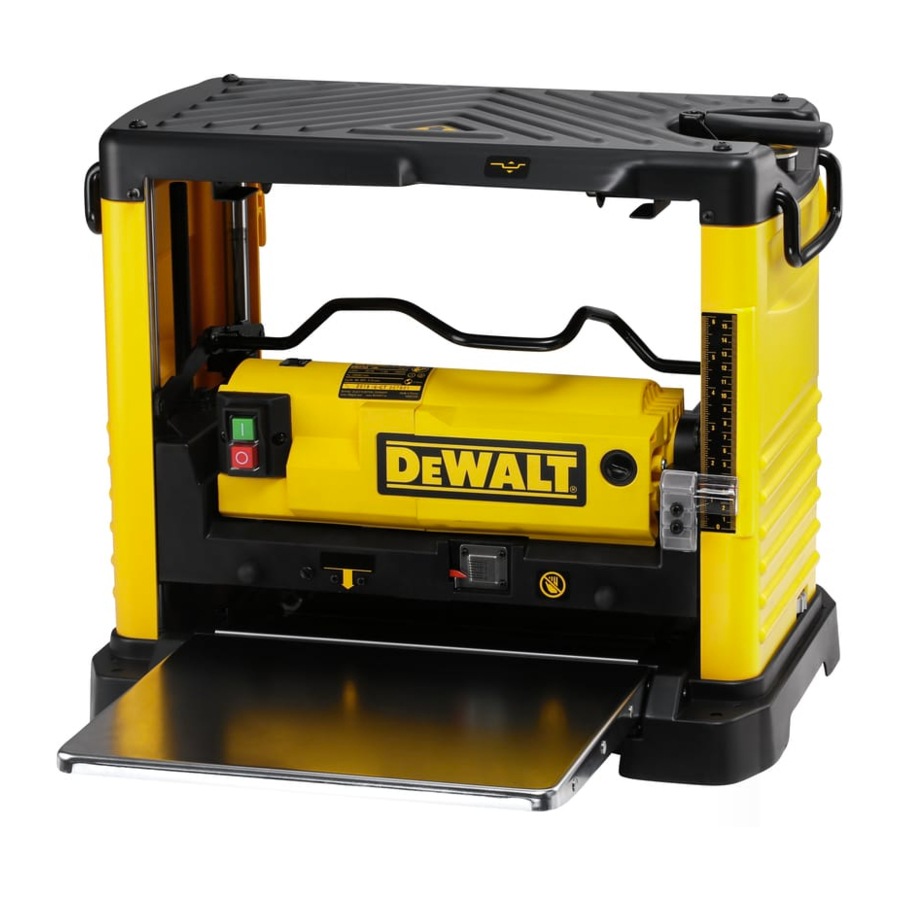
DeWalt DW733 Instruction Manual
12-1/2" (318 mm) heavy duty portable thickness planer
Hide thumbs
Also See for DW733:
- Manual (89 pages) ,
- Original instructions manual (72 pages) ,
- Instruction manual (32 pages)
Advertisement
Table of Contents
- 1 Grounding Instructions
- 2 Specifications
- 3 Transporting the Planer
- 4 Depth Adjustment
- 5 Proper Planing Technique
- 6 On/Off Switch
- 7 Planing
- 8 Changing Knives
- 9 Installing a New Belt
- 10 Calibrating the Depth Adjustment Scale
- 11 Levelling the Table Extensions
- 12 Sharpening Knives
- 13 Maintenance
- Download this manual
Before returning this product call
1-800-4-D
Questions? See us in the World Wide Web at www.dewalt.com
INSTRUCTION MANUAL
GUIDE D'UTILISATION
MANUAL DE INSTRUCCIONES
DW733
12-1/2" (318 mm) Heavy Duty Portable Thickness Planer
Dégauchisseuse portative de service intensif de 318 mm (12 1/2 po)
Cepillo portátil de 318 mm (12-1/2") para trabajo pesado
WALT
E
INSTRUCTIVO DE OPERACIÓN, CENTROS DE SERVICIO Y PÓLIZA
DE GARANTÍA. ADVERTENCIA: LÉASE ESTE INSTRUCTIVO ANTES
DE USAR EL PRODUCTO.
IF YOU SHOULD EXPERIENCE A PROBLEM WITH YOUR DEWALT PURCHASE,
CALL 1-800-4 DEWALT.
IN MOST CASES, A DEWALT REPRESENTIVE CAN RESOLVE
YOUR PROBLEM OVER THE PHONE.
IF YOU HAVE A SUGGESTION OR COMMENT, GIVE US A CALL.
YOUR FEEDBACK IS VITAL TO THE SUCCESS OF DEWALT'S
QUALITY IMPROVEMENT PROGRAM.
Advertisement
Table of Contents

Summary of Contents for DeWalt DW733
- Page 1 IF YOU SHOULD EXPERIENCE A PROBLEM WITH YOUR DEWALT PURCHASE, CALL 1-800-4 DEWALT. Before returning this product call IN MOST CASES, A DEWALT REPRESENTIVE CAN RESOLVE YOUR PROBLEM OVER THE PHONE. IF YOU HAVE A SUGGESTION OR COMMENT, GIVE US A CALL.
- Page 2 IF YOU HAVE ANY QUESTIONS OR COMMENTS ABOUT THIS OR ANY D WALT TOOL, CALL US TOLL FREE AT: 1-800-4-D WALT (1-800-433-9258) WALT… BUILT JOBSITE TOUGH WALT high performance industrial tools are made for America’s toughest industrial and construction applications. The design of every tool in the line –...
-
Page 3: Grounding Instructions
Important Safety Instructions (For all tools) Important Safety Instructions WARNING: When using electric tools, basic safety precautions should always be followed • KEEP GUARDS IN PLACE and in working order. to reduce risk of fire, electric shock, and personal injury, including the following: •... -
Page 4: Specifications
until it comes to a complete stop. SAVE THESE INSTRUCTIONS Additional Safety Rules for Planers Specifications • To reduce the risk of injury, user must read and understand instruction manual before operating planer. Input ....120V AC, 15 Amp •... -
Page 5: Transporting The Planer
FIG. 4 FIG. 8 support or moved to other job sites and reclamped. HEAD LOCK NOTE: If you elect to mount your planer to a piece of LEVER plywood, make sure that the mounting screws don’t protrude from the bottom of the wood. The plywood must sit flush on the work support. -
Page 6: Proper Planing Technique
MATERIAL REMOVAL SCALE FIG. 11 Your planer is equipped with a material removal scale, MATERIAL which indicates the amount of wood being removed in a REMOVAL planing operation. (Fig. 11 ) Ensure the workpiece is under GAUGE the material removal gauge label on the front of the tool. The material removal gauge readout is to the right of this label. - Page 7 CUTTERHEAD LOCK LEVER FIG. 20 FIG. 15 FIG. 18 ALLEN SCREW KNIFE TABLE A 3/32 FIG. 19 Soft Wood 1/16 Hard FIG. 16 Wood 1/32 Width of Stock (inches) BOLTS For best results, plane both sides of the workpiece to reach •...
-
Page 8: Planing
remove the bow, use a jointer. KNIFE GAUGES FIG. 21 Planing FIG. 23 After making all adjustments, turn the tool on and wait until the knives reach full speed. The workpiece should not be in contact with the feed rollers or the cutterhead when the tool is switched on. -
Page 9: Installing A New Belt
FIG. 26 5) Remove the knife gauges and rotate the cutterhead until its reading matches the finished thickness of the back to the position shown in Figure 18. Replace and workpiece. Securely re-tighten the screws. retighten the six middle bolts. Bolts should be tighten to Levelling the Table Extensions a torque of 50 in.


