Table of Contents
Advertisement
Quick Links
Advertisement
Table of Contents

Related Manuals for Motorola WiNG 5.6


Summary of Contents for Motorola WiNG 5.6
- Page 1 Motorola Solutions WiNG 5.6 ACCESS POINT SYSTEM REFERENCE GUIDE...
- Page 3 MOTOROLA SOLUTIONS WING 5.6 ACCESS POINT SYSTEM REFERENCE GUIDE MN000335A01 Revision A March 2014...
- Page 4 Motorola Solutions reserves the right to make changes to any software or product to improve reliability, function, or design. Motorola Solutions does not assume any product liability arising out of, or in connection with, the application or use of any product, circuit, or application described herein.
-
Page 5: Table Of Contents
TABLE OF CONTENTS About this Guide Chapter 1, Overview 1.1 About the Motorola Solutions WiNG 5 Software ......................1-3 Chapter 2, Web User Interface Features 2.1 Accessing the Web UI ..............................2-2 2.1.1 Browser and System Requirements ........................2-2 2.1.2 Connecting to the Web UI ..........................2-2 2.2 Glossary of Icons Used ..............................2-4... - Page 6 WiNG 5.6 Access Point System Reference Guide 3.1.1.6 Wireless LAN Setup ..........................3-15 3.1.1.7 Summary And Commit Screen ........................3-19 3.1.1.8 Adopt to a controller ..........................3-20 3.1.2 Advanced Setup Wizard ...........................3-21 3.1.2.1 Network Topology Selection ........................3-24 3.1.2.2 LAN Configuration ...........................3-25 3.1.2.3 WAN Configuration ..........................3-27 3.1.2.4 Radio Configuration ..........................3-29...
- Page 7 Table of Contents 5.2.6.3 L2TPv3 Profile Configuration ........................5-70 5.2.6.4 IGMP Snooping ............................5-80 5.2.6.5 MLD Snooping ............................5-82 5.2.6.6 Quality of Service (QoS) ..........................5-84 5.2.6.7 Spanning Tree Configuration ........................5-86 5.2.6.8 Routing ..............................5-89 5.2.6.9 Dynamic Routing (OSPF) ..........................5-92 5.2.6.10 Forwarding Database ..........................5-107 5.2.6.11 Bridge VLAN ............................5-109 5.2.6.12 Cisco Discovery Protocol Configuration ....................5-118 5.2.6.13 Link Layer Discovery Protocol Configuration ..................5-119 5.2.6.14 Miscellaneous Network Configuration ....................5-120...
- Page 8 WiNG 5.6 Access Point System Reference Guide 5.4.5.4 Overriding the Network Configuration ....................5-270 5.4.5.5 Overriding a Security Configuration ......................5-331 5.4.5.6 Overriding the Virtual Router Redundancy Protocol (VRRP) Configuration ..........5-353 5.4.5.7 Profile Critical Resources ........................5-358 5.4.5.8 Overriding a Services Configuration .....................5-361 5.4.5.9 Overriding a Management Configuration .....................5-362...
- Page 9 Table of Contents 6.7 Mesh QoS Policy .................................6-93 6.8 Passpoint Policy ................................6-100 Chapter 7, Network Configuration 7.1 Policy Based Routing (PBR) ............................7-2 7.2 L2TP V3 Configuration ..............................7-8 7.3 Crypto CMP Policy ..............................7-12 7.4 AAA Policy ..................................7-15 7.5 AAA TACACS Policy ..............................7-26 7.6 Alias ....................................7-42 7.6.1 Network Basic Alias ............................7-42 7.6.2 Network Group Alias ............................7-45...
- Page 10 WiNG 5.6 Access Point System Reference Guide 9.6.1 Creating RADIUS Groups ..........................9-38 9.6.1.1 Creating RADIUS Groups ........................9-41 9.6.2 Defining User Pools ............................9-43 9.6.3 Configuring the RADIUS Server ........................9-46 9.7 Services Deployment Considerations .........................9-55 Chapter 10, Management Access 10.1 Creating Administrators and Roles .........................10-2 10.2 Setting the Access Control Configuration ........................10-5...
- Page 11 Table of Contents 12.1.12 Re-elect Controller ............................12-48 12.2 Certificates ................................12-50 12.2.1 Certificate Management ..........................12-50 12.2.2 RSA Key Management ..........................12-55 12.2.3 Certificate Creation ............................12-60 12.2.4 Generating a Certificate Signing Request (CSR) ..................12-62 12.3 Smart RF .................................12-65 12.3.1 Managing Smart RF for a RF Domain ......................12-65 12.4 Operations Deployment Considerations .........................12-68 Chapter 13, Statistics 13.1 System Statistics ..............................13-2...
- Page 12 WiNG 5.6 Access Point System Reference Guide 13.3.4.3 AP Self Adoption History ........................13-65 13.3.4.4 Pending Adoptions ..........................13-66 13.3.5 AP Detection ..............................13-67 13.3.6 Wireless Clients ............................13-68 13.3.7 Wireless LANs ..............................13-69 13.3.8 Policy Based Routing ............................13-71 13.3.9 Radios ................................13-72 13.3.9.1 Status ..............................13-73 13.3.9.2 RF Statistics ............................13-74...
- Page 13 Table of Contents 13.3.24 VPN ................................13-124 13.3.24.1 IKESA ...............................13-124 13.3.24.2 IPSec ..............................13-125 13.3.25 Certificates ..............................13-126 13.3.25.1 Trustpoints ............................13-126 13.3.25.2 RSA Keys ............................13-128 13.3.26 WIPS .................................13-129 13.3.26.1 WIPS Client Blacklist ........................13-129 13.3.26.2 WIPS Events ............................13-130 13.3.27 Sensor Servers ............................13-131 13.3.28 Bonjour Services ............................13-132 13.3.29 Captive Portal ............................13-133 13.3.30 Network Time ............................13-135 13.3.30.1 NTP Status ............................13-135...
- Page 14 WiNG 5.6 Access Point System Reference Guide B.3.11 GNU Lesser General Public License, version 2.0 ..................B-43 B.3.12 GNU Lesser General Public License, version 2.1 ..................B-48 B.3.13 MIT License ..............................B-53 B.3.14 Mozilla Public License, version 2 ........................B-54 B.3.15 The Open LDAP Public License ........................
-
Page 15: About This Guide
NOTE: ES6510 is an Ethernet Switch managed by a wireless controller such as RFS4000/RFS6000/ RFS7000/NX4500/NX4524/NX6500/NX6524/NX7500/NX9000/NX9500/NX9510. ES6510 does not have radios and does not provide WLAN support. This section is organized into the following: • Document Convention • Notational Conventions • Motorola Solutions Enterprise Mobility Support Center • Motorola Solutions End-User Software License Agreement... -
Page 16: Notational Conventions
WiNG 5.6 Access Point System Reference Guide Document Convention The following conventions are used in this document to draw your attention to important information: NOTE: Indicates tips or special requirements. CAUTION: Indicates conditions that can cause equipment damage or data loss. - Page 17 • Software type and version number Motorola Solutions responds to calls by e-mail, telephone or fax within the time limits set forth in support agreements. If you purchased your Enterprise Mobility business product from a Motorola Solutions business partner, contact that business partner for support.
- Page 18 (ii) means any modifications, enhancements, new versions and new releases of the software provided by Motorola Solutions; and (iii) may contain items of software owned by a third party supplier. The term “Software” does not include any third party software provided under separate license or third party software not licensable under the terms of this Agreement.
- Page 19 5. OWNERSHIP AND TITLE 5.1 Motorola Solutions, its licensors, and its suppliers retain all of their proprietary rights in any form in and to the Software and Documentation, including, but not limited to, all rights in patents, patent applications, inventions, copyrights, trademarks, trade secrets, trade names, and other proprietary rights in or relating to the Software and Documentation.
- Page 20 8.1 Unless otherwise specified in the applicable warranty statement, the Documentation or in any other media at the time of shipment of the Software by Motorola Solutions, and for the warranty period specified therein, for the first 120 days after initial shipment of the Software to the End-User Customer, Motorola Solutions warrants that the Software, when installed and/or used properly, will be free from reproducible defects that materially vary from its published specifications.
- Page 21 11.4 Waiver. No waiver of a right or remedy of a Party will constitute a waiver of another right or remedy of that Party. 11.5 Assignments. Motorola Solutions may assign any of its rights or sub-contract any of its obligations under this End-User License Agreement or encumber or sell any of its rights in any Software, without prior notice to or consent of End-User Customer.
- Page 22 WiNG 5.6 Access Point System Reference Guide...
-
Page 23: Chapter 1, Overview
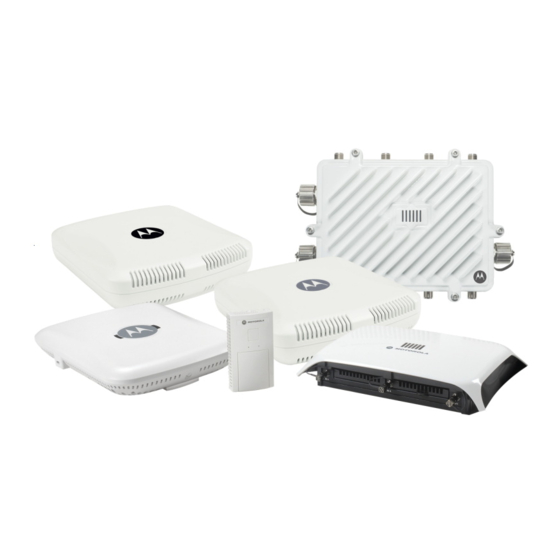
CHAPTER 1 OVERVIEW Motorola Solutions’ family of WING 5.6 supported access points enable high performance with secure and resilient wireless voice and data services to remote locations with the scalability required to meet the needs of large distributed enterprises. AP6511, AP6521, AP6522, AP6532, AP6562, AP71XX, AP81XX and AP82XX access points and ES6510 model ethernet switch can now use WiNG 5 software as its onboard operating system. - Page 24 1 - 2 WiNG 5.6 Access Point System Reference Guide is optimized to prevent wired congestion and wireless congestion. Traffic flows dynamically, based on user and application, and finds alternate routes to work around network choke points. NOTE: This guide describes the installation and use of the WiNG 5 software designed specifically for AP6511, AP6521, AP6522, AP6532, AP6562, AP71XX, AP81XX and AP82XX access points and ES6510 model ethernet switch.
-
Page 25: About The Motorola Solutions Wing 5 Software
Deploying a new WiNG 5 access point managed network does not require the replacement of existing Motorola Solutions access points. WiNG 5 enables the simultaneous use of existing architectures from Motorola Solutions and other vendors, even if those other architectures are centralized models. - Page 26 1 - 4 WiNG 5.6 Access Point System Reference Guide...
-
Page 27: Chapter 2, Web User Interface Features
CHAPTER 2 WEB USER INTERFACE FEATURES The access point’s resident user interface contains a set of features specifically designed to enable either Virtual Controller AP, Standalone AP or Adopt to Controller functionality. In Virtual Controller AP mode, an access point can manage up to 24 other access points of the same model and share data amongst managed access points. -
Page 28: Accessing The Web Ui
1 GB of RAM for the UI to display and function properly. The Web UI is based on Flex, and does not use Java as the underlying UI framework. Motorola Solutions recommends using a resolution of 1280 x 1024 pixels for using the GUI. - Page 29 2 - 3 Figure 2-1 Access Point Web UI Login screen 9. Enter the default username admin in the Username field. 10. Enter the default password motorola in the Password field. 11. Select the Login button to load the management interface.
-
Page 30: Glossary Of Icons Used
2 - 4 WiNG 5.6 Access Point System Reference Guide 2.2 Glossary of Icons Used Web User Interface Features The access point interface utilizes a number of icons designed to interact with the system, gather information from managed devices and obtain status. This chapter is a compendium of the icons used, and is organized as follows: •... -
Page 31: Dialog Box Icons
Web User Interface Features 2 - 5 Create new policy – Select this icon to create a new policy. Policies define different configuration parameters that can be applied to device configurations, and device profiles. Edit policy – Select this icon to edit an existing configuration item or policy. To edit a policy, select the policy and this icon. -
Page 32: Status Icons
2 - 6 WiNG 5.6 Access Point System Reference Guide 2.2.4 Status Icons Glossary of Icons Used These icons define device status, operations on the wireless controller, or any other action that requires a status being returned to the user. - Page 33 Web User Interface Features 2 - 7 Radio QoS Policy – Indicates a QoS policy configuration has been impacted. AAA Policy – Indicates an Authentication, Authorization and Accounting (AAA) policy has been impacted. AAA policies define RADIUS authentication and accounting parameters. Association ACL –...
- Page 34 2 - 8 WiNG 5.6 Access Point System Reference Guide Device Categorization – Indicates a device categorization policy is being applied. This is used by the intrusion prevention system to categorize APs or wireless clients as either neighbors or sanctioned devices. This enables these devices to bypass the intrusion prevention system.
-
Page 35: Configuration Objects
Web User Interface Features 2 - 9 2.2.6 Configuration Objects Glossary of Icons Used Configuration icons are used to define the following: Configuration – Indicates an item capable of being configured by the access point’s interface. View Events / Event History – Defines a list of events. Select this icon to view events or view the event history. -
Page 36: Access Type Icons
2 - 10 WiNG 5.6 Access Point System Reference Guide 2.2.8 Access Type Icons Glossary of Icons Used The following icons display a user access type: Web UI – Defines a Web UI access permission. A user with this permission is permitted to access an associated device’s Web UI. -
Page 37: Device Icons
Web User Interface Features 2 - 11 Help Desk – Indicates help desk privileges. A help desk user is allowed to use troubleshooting tools like sniffers, execute service commands, view or retrieve logs and reboot an access point. Web User – Indicates a Web user privilege. A Web user is allowed accessing the access point’s Web user interface. - Page 38 2 - 12 WiNG 5.6 Access Point System Reference Guide...
-
Page 39: Chapter 3, Quick Start
CHAPTER 3 QUICK START Access points can utilize an initial setup wizard to streamline the process of initially accessing the wireless network. The wizard defines the access point’s operational mode, deployment location, basic security, network and WLAN settings. For instructions on how to use the initial setup wizard, see Using the Initial Setup Wizard on page 3-2. -
Page 40: Using The Initial Setup Wizard
3 - 2 WiNG 5.6 Access Point System Reference Guide 3.1 Using the Initial Setup Wizard Quick Start Once the access point is installed and powered on, complete the following steps to get the access point up and running and access management functions: 1. - Page 41 Quick Start 3 - 3 Figure 3-2 Initial Setup Wizard NOTE: The Initial Setup Wizard displays the same pages and content for each access point model supported. The only difference being the number of radios configurable by model, as an AP7131 model can support up to three radios, AP6522, AP6532, AP6562, AP81XX, 82XX and AP71XX models support two radios and AP6511 and AP6521 models support a single radio.
- Page 42 3 - 4 WiNG 5.6 Access Point System Reference Guide Figure 3-3 Initial Setup Wizard - Navigation Panel - Typical Setup Wizard A green check mark to the left of an item in the Navigation Panel defines the listed task as having its minimum required configuration parameters set correctly.
-
Page 43: Typical Setup Wizard
Quick Start 3 - 5 6. Select Save/Commit within each page to save the updates made to that page's configuration. Select Next to proceed to the next page listed in the Navigation Panel. Select Back to revert to the previous screen without saving your updates. NOTE: While you can navigate to any page in the navigation panel, you cannot complete the Initial Setup Wizard until each task in the Navigation Panel has a green check mark. - Page 44 Mode on page 3-9. NOTE: If designating the access point as a Standalone AP, Motorola Solutions recommends the access point’s UI be used exclusively to define its device configuration, and not the CLI. The CLI provides the ability to define more than one profile and the UI does not.
- Page 45 Quick Start 3 - 7 • Adopted to Controller - Select this option when deploying the access point as a controller managed (Dependent mode) access point. Selecting this option closes the Initial AP Setup Wizard. An adopted access point obtains its configuration from a profile stored on its managing controller.
-
Page 46: Virtual Controller Ap Mode
3 - 8 WiNG 5.6 Access Point System Reference Guide 3.1.1.1 Virtual Controller AP Mode Using the Initial Setup Wizard When more than one access point is deployed, a single access point can function as a Virtual Controller AP. Up to 24 access points can be connected to, and managed by a single Virtual Controller AP of the same access point model. -
Page 47: Standalone Mode
In the Standalone mode, the access point is not adopted to a wireless controller. Select this option to deploy this access point as an autonomous fat access point. CAUTION: If designating the access point as a Standalone AP, Motorola Solutions recommends the access point’s UI be used exclusively to define its device configuration, and not the CLI. -
Page 48: Network Topology Selection
3 - 10 WiNG 5.6 Access Point System Reference Guide 3.1.1.3 Network Topology Selection Typical Setup Wizard Use the Network Topology screen to define how the access point manages network traffic. The available modes are: Figure 3-6 Initial Setup Wizard - Network Topology screen for Typical Setup Wizard •... -
Page 49: Lan Configuration
Quick Start 3 - 11 3.1.1.4 LAN Configuration Typical Setup Wizard Use the LAN Configuration screen to set the access point's DHCP and LAN network address configuration. Figure 3-7 Initial Setup Wizard - LAN Configuration screen for Typical Setup Wizard 1. - Page 50 3 - 12 WiNG 5.6 Access Point System Reference Guide option is not selected, a primary and secondary DNS resource must be specified. DNS forwarding is useful when a request for a domain name is made but the DNS server, responsible for converting the name into its corresponding IP address, cannot locate the matching IP address.
-
Page 51: Wan Configuration
Quick Start 3 - 13 3.1.1.5 WAN Configuration Typical Setup Wizard NOTE: This option is only available when Router Mode is selected in the Network Topology screen. Use the WAN Setting screen to define network address settings for the WAN interface. The WAN interface connects the access point to a wired local area network or backhaul. -
Page 52: Wireless Lan Setup
3 - 14 WiNG 5.6 Access Point System Reference Guide • Enable NAT on the WAN Interface – Select the option to enable Network Address Translation on the selected GE interface. 2. Select Next. The Typical Setup Wizard displays the... - Page 53 Quick Start 3 - 15 3.1.1.6 Wireless LAN Setup Typical Setup Wizard A Wireless Local Area Network (WLAN) is a data-communications system and local area network that flexibly extends the functionality of a wired LAN. A WLAN links two or more computers or devices using spread-spectrum or OFDM modulation based technology.
- Page 54 3 - 16 WiNG 5.6 Access Point System Reference Guide • Captive Portal Authentication and No Encryption – Configures a network that uses a RADIUS server to authenticate users before allowing them on to the network. Once on the network, no encryption is used for the data being transmitted through the network.
- Page 55 Quick Start 3 - 17 3.1.1.6.1 RADIUS Server Configuration Wireless LAN Setup Use the RADIUS Server Configuration screen to configure the users for the onboard RADIUS server. Use the screen to add, modify and remove RADIUS users. Figure 3-10 Initial Setup Wizard - RADIUS Server Configuration screen for Typical Setup Wizard Use the Add User button to add a new RADIUS user.
- Page 56 3 - 18 WiNG 5.6 Access Point System Reference Guide Figure 3-11 Initial Setup Wizard - RADIUS Server Configuration - Add User screen for Typical Setup Wizard 1. Use the Add User dialog to provide user information to add to the RADIUS server user database.
-
Page 57: Summary And Commit Screen
Quick Start 3 - 19 3.1.1.7 Summary And Commit Screen Typical Setup Wizard The Summary And Commit screen displays a complete overview of the configurations made in the previous screens. There is no user intervention or additional settings required. The Summary and Commit screen is an additional means of validating the configuration before it is deployed. -
Page 58: Adopt To A Controller
3 - 20 WiNG 5.6 Access Point System Reference Guide 3.1.1.8 Adopt to a controller Using the Initial Setup Wizard Adopted to Controller is the default behavior of the access point. When the access point is switched on for the first time, it looks for a wireless controller on the default subnet and that runs the same WiNG firmware version and automatically adopts to it. -
Page 59: Advanced Setup Wizard
Quick Start 3 - 21 3.1.2 Advanced Setup Wizard Using the Initial Setup Wizard Advanced Setup is the recommended wizard for users who want more control on how the access point is configured beyond minimum default settings. This wizard provides additional radio and system information settings. The Advanced Setup wizard consists of the following: •... - Page 60 Standalone Mode on page 3-9. NOTE: If designating the access point as a Standalone AP, Motorola Solutions recommends the access point’s UI be used exclusively to define its device configuration, and not the CLI. The CLI provides the ability to define more than one profile and the UI does not.
- Page 61 Quick Start 3 - 23 • Adopted to Controller - Select this option when deploying the access point as a controller managed (Dependent mode) access point. Selecting this option closes the Initial AP Setup Wizard. An adopted access point obtains its configuration from a profile stored on its managing controller.
-
Page 62: Network Topology Selection
3 - 24 WiNG 5.6 Access Point System Reference Guide 3.1.2.1 Network Topology Selection Advanced Setup Wizard Use the Network Topology screen to define how the access point manages network traffic. The available modes are: Figure 3-15 Initial Setup Wizard - Access Point Mode screen for Advanced Setup Wizard •... -
Page 63: Lan Configuration
Quick Start 3 - 25 3.1.2.2 LAN Configuration Advanced Setup Wizard Use the LAN Configuration screen to configure the parameters required for setting a Local Area Network (LAN) on the access point. Figure 3-16 Initial Setup Wizard - LAN Configuration screen for Advanced Setup Wizard 1. - Page 64 3 - 26 WiNG 5.6 Access Point System Reference Guide • Default Gateway - Define a default gateway address for use with the DHCP server configuration. This is a required parameter. • DNS Forwarding - Select this option to allow a DNS server to translate domain names into IP addresses. If this option is not selected, a primary and secondary DNS resource must be specified.
-
Page 65: Wan Configuration
Quick Start 3 - 27 3.1.2.3 WAN Configuration Advanced Setup Wizard NOTE: This option is only available when Router Mode is selected in the Network Topology screen of the Advanced Setup Wizard. The Advanced Setup Wizard displays the WAN Setting screen to define DHCP and network address information for the WAN interface. -
Page 66: Radio Configuration
3 - 28 WiNG 5.6 Access Point System Reference Guide • Select the port that’s connected to the WAN – Select the port that is connected to the WAN. • Enable NAT on the WAN Interface – Select the option to enable Network Address Translation on the selected GE interface. - Page 67 Quick Start 3 - 29 3.1.2.4 Radio Configuration Advanced Setup Wizard Use the Radio Configuration screen to define radio support for the 2.4 GHz radio band, 5.0 GHz radio band or set the radio as a dedicated sensor. NOTE: The Radio Configuration screen displays separate configurable fields for each access point radio.
- Page 68 3 - 30 WiNG 5.6 Access Point System Reference Guide • Power Level - Use the spinner control to select a 1 - 23 dBm minimum power level to assign to this radio in selected 2.4 GHz or 5.0 GHz band. 1 dBm is the default setting.
-
Page 69: Wireless Lan Setup
Quick Start 3 - 31 3.1.2.5 Wireless LAN Setup Advanced Setup Wizard A Wireless Local Area Network (WLAN) is a data-communications system and wireless local area network that flexibly extends the functionality of a wired LAN. A WLAN links two or more computers or devices using spread-spectrum or OFDM modulation based technology. - Page 70 3 - 32 WiNG 5.6 Access Point System Reference Guide users before allowing them on to the network. Once on the network, no encryption is used for the data transmitted through the network. Select this option to use a Web page (either internally or externally hosted) to authenticate users before access is granted to the network.
-
Page 71: System Information
Quick Start 3 - 33 3.1.2.6 System Information Advanced Setup Wizard Use the System Information screen to define the device’s location, contact information for an administrator, and the country where this access point is deployed. Figure 3-20 Initial Setup Wizard - System Information screen for the Advanced Setup Wizard •... -
Page 72: Summary And Commit Screen
3 - 34 WiNG 5.6 Access Point System Reference Guide 3.1.2.7 Summary And Commit Screen Advanced Setup Wizard The Summary And Commit screen displays an overview of the updates made using the Advanced Setup Wizard. There is no user intervention or additional settings required. This screen is an additional means of validating the configuration before it is deployed. -
Page 73: Adopt To A Controller
Quick Start 3 - 35 3.1.2.8 Adopt to a controller Advanced Setup Wizard When the access point is powered on for the first time, it looks for a wireless controller on the default subnet running the same firmware version and automatically adopts to it. When Adopted to Controller is selected, further configuration settings are displayed in the same screen. - Page 74 3 - 36 WiNG 5.6 Access Point System Reference Guide...
-
Page 75: Chapter 4, Dashboard
CHAPTER 4 DASHBOARD The dashboard allows network administrators to review and troubleshoot the operation of the devices comprising the access point managed network. Use the dashboard to review the current network topology, assess the network’s component health and diagnose problematic device behavior. By default, the Dashboard screen displays the System Dashboard, which is the top level in the device hierarchy. -
Page 76: Dashboard Conventions
4 - 2 WiNG 5.6 Access Point System Reference Guide 4.1 Dashboard Dashboard The Dashboard screen displays device information organized by device association and inter-connectivity between an access point and connected wireless clients. To review dashboard information: 1. Select Dashboard. Expand the... -
Page 77: Health
Dashboard 4 - 3 4.1.1.1 Health Dashboard Conventions Health tab displays performance and utilization data for the access point managed network. Figure 4-2 Dashboard - Health tab For more information see: • Device Details • Radio RF Quality Index • Radio Utilization Index •... - Page 78 4 - 4 WiNG 5.6 Access Point System Reference Guide Figure 4-3 Dashboard - Health tab - Device Details field Device Details field displays the name assigned to the selected access point, factory encoded MAC address, primary IP address, model type, RF Domain, software version, uptime, CPU and RAM information and system clock. Use this data to determine whether a software upgrade is warranted, or if the system clock needs adjustment.
- Page 79 Dashboard 4 - 5 Periodically select Refresh (at the bottom of the screen) to update the RF quality data. 4.1.1.1.3 Radio Utilization Index Dashboard Conventions Radio Utilization Index displays how efficiently the RF medium is used by the access point. Traffic utilization is defined as the percentage of throughput relative to the maximum possible throughput.
- Page 80 4 - 6 WiNG 5.6 Access Point System Reference Guide 1. The Client RF Quality Index displays the following: Worst 5 Lists the worst 5 performing client radios connected to the access point. The RF Quality Index measures the overall effectiveness of the RF environment as a percentage. Its a function of the connect rate in both directions, as well as the retry rate and the error rate.
-
Page 81: Inventory
Dashboard 4 - 7 4.1.1.2 Inventory Dashboard Conventions Inventory tab displays information relative to the devices managed by the selected access point. The Inventory screen affords a system administrator an overview of the number and state of managed devices. The screen contains links to display more granular data specific to a radio. - Page 82 4 - 8 WiNG 5.6 Access Point System Reference Guide 4.1.1.2.1 Radio Types Inventory Radio Types field displays the total number and types of radios managed by the selected access point. Figure 4-8 Dashboard - Inventory tab - Radio Types field...
- Page 83 Dashboard 4 - 9 Figure 4-10 Dashboard - Inventory tab - Wireless Clients field Information within the Wireless Clients field is presented in two tables. The first table lists the total number of wireless clients managed by this access point. The second table lists an ordered ranking of radios based on their supported client count. Use this information to assess if an access point managed radio is optimally deployed in respect to its radio type and intended client support requirements.
-
Page 84: Network View
4 - 10 WiNG 5.6 Access Point System Reference Guide 4.2 Network View Dashboard Network View displays device topology association between a selected access point, its RF Domain and its connected clients. Access points and clients can be selected and viewed using various color schemes in respect to neighboring access points, connected devices and performance criteria. -
Page 85: Network View Display Options
Dashboard 4 - 11 Figure 4-13 Network View - System Browser 4.2.1 Network View Display Options Network View 1. Select the blue Options link right under the Network View banner to display a menu for different device interaction display options. Figure 4-14 Network View - Display Options 2. -
Page 86: Device Specific Information
4 - 12 WiNG 5.6 Access Point System Reference Guide and error rates. Quality results include: Red (Bad Quality), Orange (Poor Quality), Yellow (Fair Quality) and Green (Good Quality). • Vendor – Displays the device manufacturer. • Band – Select this option to filter based on the 2.4 or 5.0 GHz radio band of connected clients. Results include: Yellow (2.4 GHz radio band) and Blue (5.0 GHz radio band). -
Page 87: Chapter 5, Device Configuration
CHAPTER 5 DEVICE CONFIGURATION Access points can either be assigned unique configurations to support a particular deployment objective or have an existing RF Domain or profile configuration modified (overridden) to support a requirement that deviates its configuration from the configuration shared by its peer access points. Refer to the following to set an access point’s sensor functionality, Virtual Controller AP designation, and license and certificate usage configuration: •... -
Page 88: Rf Domain Configuration
5 - 2 WiNG 5.6 Access Point System Reference Guide 5.1 RF Domain Configuration Device Configuration An access point’s configuration consists of numerous elements including a RF Domain, WLAN and device specific settings. RF Domains are used to assign regulatory, location and relevant policies to access points of the same model. For example, an AP6532 RF Domain can only be applied to another AP6532 model. -
Page 89: Rf Domain Sensor Configuration
In addition to dedicated Motorola Solutions AirDefense sensors, an access point radio can function as a sensor and upload information to a dedicated WIPS server (external to the access point). Unique WIPS server configurations can be used to ensure... -
Page 90: Rf Client Name Configuration
5 - 4 WiNG 5.6 Access Point System Reference Guide WIPS is not supported on a WLAN basis, rather, sensor functionality is supported on the access point radio(s) available to each managed WLAN. When an access point radio is functioning as a WIPS sensor, it is able to scan in sensor mode across all legal channels within the 2.4 and 5.0 GHz band. -
Page 91: Rf Domain Alias Configuration
Device Configuration 5 - 5 3. Select RF Domains from the options on left-hand side of the UI. 4. Select the Client Name tab. Figure 5-3 RF Domain Client Configuration screen 5. Either select the + Add Row button to create a new client configuration or highlight an existing configuration and select Delete icon to remove it. - Page 92 5 - 6 WiNG 5.6 Access Point System Reference Guide • RF Domain aliases are defined from Configuration > Devices > RF Domain > Alias screen. These aliases are available for use for a site as a RF Domain is site specific. RF Domain alias values override alias values defined in a global alias or a profile alias configuration.
-
Page 93: Network Basic Alias
Device Configuration 5 - 7 5.1.3.1 Network Basic Alias RF Domain Configuration A basic alias is a set of configurations that consist of VLAN, Host, Network and Address Range alias configurations. VLAN configuration is a configuration for optimal VLAN re-use and management for local and remote deployments. A host alias configuration is for a particular host device’s IP address. - Page 94 5 - 8 WiNG 5.6 Access Point System Reference Guide Use the VLAN Alias field to create unique aliases for VLANs that can be used at different deployments. For example, if a named VLAN is defined as 10 for the central network, and the VLAN is set at 26 at a remote location, the VLAN can be overridden at the deployment location with an alias.
- Page 95 Device Configuration 5 - 9 8. Select + Add Row to define Network Alias settings: Use the Network Alias field to create aliases for IP networks that can be utilized at different deployments. For example, if a central network ACL defines a network as 192.168.10.0/24, and a remote location’s network range is 172.16.10.0/24, the ACL can be overridden at the remote location to suit their local (but remote) requirement.
-
Page 96: Network Group Alias
5 - 10 WiNG 5.6 Access Point System Reference Guide 5.1.3.2 Network Group Alias RF Domain Configuration A network group alias is a set of configurations that consist of host and network configurations. Network configurations are complete networks in the form 192.168.10.0/24 or IP address range in the form 192.168.10.10-192.168.10.20. Host configuration is in the form of single IP address, 192.168.10.23. - Page 97 Device Configuration 5 - 11 5. Select Edit to modify the attributes of an existing policy or Delete to remove obsolete policies from the list of those available. Select to create a new Network Group Alias. Copy to copy an existing policy or Rename to rename an existing policy.
-
Page 98: Network Service Alias
5 - 12 WiNG 5.6 Access Point System Reference Guide 9. Select when completed to update the network group alias rules. Select Reset to revert the screen back to its last saved configuration. 5.1.3.3 Network Service Alias RF Domain Configuration A network service alias is a set of configurations that consist of protocol and port mappings. - Page 99 Device Configuration 5 - 13 Figure 5-8 RF Domain - Network Service Alias Add screen 6. If adding a new Network Service Alias, provide it a name up to 32 characters. NOTE: The Network Service Alias Name always starts with a dollar sign ($). 7.
-
Page 100: System Profile Configuration
5 - 14 WiNG 5.6 Access Point System Reference Guide 5.2 System Profile Configuration Device Configuration An access point profile enables an administrator to assign a common set of configuration parameters and policies to access points of the same model. Profiles can be used to assign common or unique network, wireless and security parameters to across a large, multi segment, site. -
Page 101: General Profile Configuration
Device Configuration 5 - 15 5.2.1 General Profile Configuration System Profile Configuration An access point profile requires unique clock synchronization settings as part of its general configuration. Network time protocol (NTP) manages time and/or network clock synchronization within the access point managed network. NTP is a client/server implementation. -
Page 102: Profile Radio Power
5 - 16 WiNG 5.6 Access Point System Reference Guide Version Use the spinner control to specify the version number used by this NTP server resource. The default setting is 0. 5. Use the RF Domain Manager field to configure how this access point behaves in standalone mode. Set the following... - Page 103 Device Configuration 5 - 17 Figure 5-10 Profile - Power screen 5. Use the Power Mode drop-down menu to set the Power Mode Configuration on this NOTE: Single radio model access points always operate using a full power configuration. The power management configurations described in this section do not apply to single radio access point models.
-
Page 104: Profile Adoption (Auto Provisioning) Configuration
5 - 18 WiNG 5.6 Access Point System Reference Guide 5.2.3 Profile Adoption (Auto Provisioning) Configuration System Profile Configuration Adoption is the process an access point uses to discover Virtual Controller APs available in the network, pick the most desirable Virtual Controller, establish an association with the Virtual Controller and optionally obtain an image upgrade, obtains its configuration and considers itself provisioned. - Page 105 Device Configuration 5 - 19 Figure 5-11 Profile Adoption screen 5. Define the Preferred Group used as optimal group of Virtual Controller for adoption. The name of the preferred group cannot exceed 64 characters. 6. Select the VLAN option to define a VLAN the access point’s associating Virtual Controller AP is reachable on.
-
Page 106: Profile Wired 802.1X Configuration
5 - 20 WiNG 5.6 Access Point System Reference Guide 10. Enter Controller Hostnames as needed to define resources for adoption. Click +Add Row to add controllers. Set the following parameters to define Controller Hostnames: Host Use the drop-down menu to specify whether the controller adoption resource is defined as a (non DNS) IP address or a hostname. -
Page 107: Profile Interface Configuration
Device Configuration 5 - 21 Figure 5-12 Profile Wired 802.1X screen 5. Set the following Wired 802.1x Settings: Dot1x Authentication Select this option to globally enable 802.1x authentication for the selected device. This Control setting is disabled by default. Dot1x AAA Policy Use the drop-down menu to select an AAA policy to associate with wired 802.1x traffic. -
Page 108: Ethernet Port Configuration
5 - 22 WiNG 5.6 Access Point System Reference Guide 5.2.5.1 Ethernet Port Configuration Profile Interface Configuration Displays the physical port reporting runtime data and statistics. The following ports are available depending on model: • AP6511 - fe1, fe2, fe3, fe4, up1 •... - Page 109 Device Configuration 5 - 23 Type Displays the physical port type. Description Displays an administrator defined description for each listed port. Admin Status A green check mark defines the port as active and currently enabled with the profile. A red “X” defines the port as currently disabled and not available for use. The interface status can be modified with the port configuration as required.
- Page 110 5 - 24 WiNG 5.6 Access Point System Reference Guide Figure 5-14 Ethernet Ports - Basic Configuration screen 7. Set the following Ethernet port Properties: Description Enter a brief description for the port (64 characters maximum). The description should reflect the port’s intended function to differentiate it from others with similar configurations.
- Page 111 Device Configuration 5 - 25 8. Define the following Cisco Discovery Protocol (CDP) and LLDP parameters to apply to the Ethernet port configuration: Cisco Discover Protocol Select this option to allow the Cisco discovery protocol for receiving data on this port. If Receive enabled, the port sends out periodic interface updates to a multicast address to advertise its presence to neighbors.
- Page 112 5 - 26 WiNG 5.6 Access Point System Reference Guide A captive portal is an access policy for providing temporary and restrictive access using a standard Web browser. Captive portals provides authenticated access by capturing and re-directing a wireless user's Web browser session to a captive portal login page where the user must enter valid credentials to access to the network.
- Page 113 Device Configuration 5 - 27 Use the IPv6 Inbound Firewall Rules drop-down menu to select the IPv6 specific firewall rules to apply to this profile’s Ethernet port configuration. IPv6 is the latest revision of the Internet Protocol (IP) designed to replace IPv4. IPV6 provides enhanced identification and location information for computers on networks routing traffic across the Internet.
- Page 114 5 - 28 WiNG 5.6 Access Point System Reference Guide Port Control Use the drop-down menu to set the port control state to apply to this port. Options include force-authorized, force-unauthorized and automatic. The default setting is port-authorized. Re Authenticate Select this setting to force clients to reauthenticate on this port.
- Page 115 Device Configuration 5 - 29 encodes additional region information after the standard RSTP BPDU as well as a number of MSTI messages. Each MSTI messages conveys spanning tree information for each instance. Each instance can be assigned a number of configured VLANs.
- Page 116 5 - 30 WiNG 5.6 Access Point System Reference Guide 22. Refer to the MSTP Configuration field to define the following: Enable as Edge Port Select to enable the port as an Edge Port for MSTP. An Edge Port is a port known to connect to a LAN which has no other bridges attached to it or is directly connected to an user device.
-
Page 117: Virtual Interface Configuration
Device Configuration 5 - 31 5.2.5.2 Virtual Interface Configuration Profile Interface Configuration A Virtual Interface is required for layer 3 (IP) access to provide layer 3 service on a VLAN. The Virtual Interface defines which IP address is associated with each VLAN ID the access point is connected to. A Virtual Interface is created for the default VLAN (VLAN 1) to enable remote administration. - Page 118 5 - 32 WiNG 5.6 Access Point System Reference Guide VLAN Displays the numerical VLAN ID associated with each listed interface. IP Address Defines whether DHCP was used to obtain the primary IP address used by the Virtual Interface configuration.
- Page 119 Device Configuration 5 - 33 Select either the Inside, Outside or None radio buttons. • Inside - The inside network is transmitting data over the network to its intended destination. On the way out, the source IP address is changed in the header and replaced by the (public) IP address. •...
- Page 120 5 - 34 WiNG 5.6 Access Point System Reference Guide 14. Set the following Router Advertisement Processing settings for the virtual interface. Router advertisements are periodically sent to hosts or sent in response to solicitation requests. The advertisement includes IPv6 prefixes and other subnet and host information.
- Page 121 Device Configuration 5 - 35 18. Set the following network information from within the IPv4 Addresses field: Enable Zero Zero configuration can be a means of providing a primary or secondary IP addresses for the Configuration virtual interface. Zero configuration (or zero config) is a wireless connection utility included with Microsoft Windows XP and later as a service dynamically selecting a network to connect based on a user's preferences and various default settings.
- Page 122 5 - 36 WiNG 5.6 Access Point System Reference Guide 21. Refer to the IPv6 Addresses field to define how IP6 addresses are created and utilized. IPv6 Mode Select this option to enable IPv6 support on this virtual interface. IPv6 is disabled by default.
- Page 123 Device Configuration 5 - 37 Figure 5-22 Virtual Interfaces - Basic Configuration screen - IPv6 tab - Add Address Prefix from Provider EUI64 Delegated Prefix Enter a 32 character maximum name for the IPv6 prefix from provider in EUI format. Using Name EUI64, a host can automatically assign itself a unique 64-bit IPv6 interface identifier without manual configuration or DHCP.
- Page 124 5 - 38 WiNG 5.6 Access Point System Reference Guide 26. Select the IPv6 RA Prefixes tab. Figure 5-24 Virtual Interfaces - Basic Configuration screen - IPv6 RA Prefixes tab 27. Use the Router Advertisement Policy drop-down menu to select and apply a policy to the virtual interface.
- Page 125 Device Configuration 5 - 39 29. Set the following IPv6 RA Prefix settings: Prefix Type Set the prefix delegation type used with this configuration. Options include, Prefix, and prefix- from-provider. The default setting is Prefix. A prefix allows an administrator to associate a user defined name to an IPv6 prefix.
-
Page 126: Port Channel Configuration
5 - 40 WiNG 5.6 Access Point System Reference Guide 32. Select the Security tab. Figure 5-26 Virtual Interfaces - Security tab 33. Use the IPv4 Inbound Firewall Rules drop-down menu to select the IPv4 specific inbound firewall rules to apply to this profile’s virtual interface configuration. - Page 127 Device Configuration 5 - 41 Figure 5-27 Profile Interfaces - Port Channels screen 1. Select the Configuration tab from the Web UI. 2. Select Devices. 3. Select System Profile from the options on left-hand side of the UI. 4. Expand the Interface menu and select Port...
- Page 128 5 - 42 WiNG 5.6 Access Point System Reference Guide Figure 5-28 Port Channels - Basic Configuration tab 7. Set the following port channel Properties: Description Enter a brief description for the port channel (64 characters maximum). The description should reflect the port channel’s intended function.
- Page 129 Device Configuration 5 - 43 8. Use the Port Channel Load Balance drop-down menu within the Client Load Balancing field to define whether port channel load balancing is conducted using a Source/Destination IP or a Source/Destination MAC as criteria. Source/ Destination IP is the default setting.
- Page 130 5 - 44 WiNG 5.6 Access Point System Reference Guide Figure 5-29 Port Channels - Security tab 12. Refer to the Access Control section. As part of the port channel’s security configuration, Inbound IPv4 IP, IPv6 IP and MAC address firewall rules are required.
- Page 131 Device Configuration 5 - 45 Trust 802.1p COS values Select this option to enable 802.1p COS values on this port channel. The default value is enabled. Trust IP DSCP Select this option to enable IP DSCP values on this port channel. The default value is enabled.
- Page 132 5 - 46 WiNG 5.6 Access Point System Reference Guide 17. Define the following PortFast parameters for the port channel’s MSTP configuration: Enable PortFast PortFast reduces the time required for a port to complete a MSTP state change from Blocked to Forward. PortFast must only be enabled on ports on the wireless controller directly connected to a server/workstation and not another hub or controller.
- Page 133 Device Configuration 5 - 47 <=10000000 bits/sec 2000000 <=100000000 bits/sec 200000 <=1000000000 bits/sec 20000 <=10000000000 bits/sec 2000 <=100000000000 bits/sec <=1000000000000 bits/sec >1000000000000 bits/sec 20. Select + Add Row as needed to include additional indexes. 21. Refer to the Spanning Tree Port Priority table.
-
Page 134: Access Point Radio Configuration
5 - 48 WiNG 5.6 Access Point System Reference Guide 5.2.5.4 Access Point Radio Configuration Profile Interface Configuration An access point profile can have its radio configuration modified once its radios have successfully associated to the network. To define a access point radio configuration: 1. - Page 135 Device Configuration 5 - 49 RF Mode Displays whether each listed radio is operating in the 802.11a/n or 802.11b/g/n radio band. If the radio is a dedicated sensor, it will be listed as a sensor to define the radio as not providing typical WLAN support.
- Page 136 5 - 50 WiNG 5.6 Access Point System Reference Guide Radio QoS Policy Use the drop-down menu to specify an existing QoS policy to apply to the access point radio in respect to its intended radio traffic. If there’s no existing suiting the radio’s intended operation, select the Create icon to define a new QoS policy that can be applied to this profile.
- Page 137 Motorola Solutions recommends that only a professional installer set the antenna gain. The default value is 0.00.
- Page 138 5 - 52 WiNG 5.6 Access Point System Reference Guide NOTE: AP6522, AP6522M, AP6532, AP6562, AP8132, AP8232, AP7131, AP7181 and AP7161 model access points can support up to 256 client connections to a single access point radio. AP6511 and AP6521 model access points (both single radio models) can support up to 128 client connections to a single radio.
- Page 139 Device Configuration 5 - 53 Short Preamble If using an 802.11bg radio, select this option for the radio to transmit using a short preamble. Short preambles improve throughput. However, some devices (SpectraLink phones) require long preambles. The default value is disabled. Guard Interval Use the drop-down menu to specify a Long or Any guard interval.
- Page 140 5 - 54 WiNG 5.6 Access Point System Reference Guide 15. Select Create New MeshPoint to open a dialog where new Mesh Points are created. 16. Select the button located at the bottom right of the screen to save the changes to the WLAN Mapping. Select Reset to revert to the last saved configuration.
- Page 141 Device Configuration 5 - 55 Figure 5-35 Access Point Radio - Advanced Settings tab 22. Refer to the Aggregate MAC Protocol Data Unit (A-MPDU) field to define how MAC service frames are aggregated by the access point radio. A-MPDU Modes Use the drop-down menu to define the A-MPDU mode supported.
- Page 142 5 - 56 WiNG 5.6 Access Point System Reference Guide Forwarding Port Use the Forward Port spinner to configure the port on which to forward captured packets to the Ekahau Engine. MAC to be forwarded Use the text area to provide a MAC address that identifies that the packet is received from Ekahau tags.
- Page 143 Device Configuration 5 - 57 30. Select the button located at the bottom right of the screen to save the changes to the Advanced Settings screen. Select Reset to revert to the last saved configuration. 5.2.5.4.1 MCS Data Rates Access Point Radio Configuration 802.11n MCS rates are defined as follows both with and without short guard intervals (SGI): Table 5.1 MCS-1Stream MCS Index...
- Page 144 5 - 58 WiNG 5.6 Access Point System Reference Guide Table 5.3 MCS-3Stream MCS Index Number of 20 MHz 20 MHz 40 MHz 40MHz Streams No SGI With SGI No SGI With SGI 58.5 121.5 86.7 130.7 173.3 175.5 364.5 216.7...
-
Page 145: Wan Backhaul Configuration
Device Configuration 5 - 59 5.2.5.5 WAN Backhaul Configuration Profile Interface Configuration A Wireless Wide Area Network (WWAN) card is a specialized network interface card that allows a network device to connect, transmit and receive data over a Cellular Wide Area Network. The AP7131N model access point has a PCI Express card slot that supports 3G WWAN cards. - Page 146 5 - 60 WiNG 5.6 Access Point System Reference Guide Figure 5-36 Profile Interface - WAN Backhaul screen 5. Refer to the WAN (3G) Backhaul configuration to specify the access point’s WAN card interface settings: WAN Interface Name Displays the WAN Interface name for the WAN 3G Backhaul card.
- Page 147 Device Configuration 5 - 61 8. Configure the IPv4 Inbound IP Firewall Rules. Use the drop-down menu to select a firewall (set of IP access connection rules) to apply to the PPPoE client connection. If a firewall rule does not exist suiting the data protection needs of the PPPoE client connection, select the Create icon to define a new rule configuration or the Edit icon to modify an existing rule.
-
Page 148: Pppoe Configuration
5 - 62 WiNG 5.6 Access Point System Reference Guide 5.2.5.6 PPPoE Configuration Profile Interface Configuration PPP over Ethernet (PPPoE) is a data-link protocol for dialup connections. PPPoE allows the access point to use a broadband modem (DSL, cable modem, etc.) for access to high-speed data and broadband networks. Most DSL providers are currently supporting (or deploying) the PPPoE protocol. - Page 149 Device Configuration 5 - 63 Figure 5-37 Profile Interface - PPPoE screen 5. Use the Basic Settings field to enable PPPoE and define a PPPoE client. Admin Status Select Enable to support a high speed client mode point-to-point connection using the PPPoE protocol.
- Page 150 5 - 64 WiNG 5.6 Access Point System Reference Guide 6. Define the following Authentication parameters for PPPoE client interoperation: Username Provide the 64 character maximum username used for authentication support by the PPPoE client. Password Provide the 64 character maximum password used for authentication by the PPPoE client.
-
Page 151: Profile Network Configuration
Device Configuration 5 - 65 5.2.6 Profile Network Configuration System Profile Configuration Setting an access point profile’s network configuration is a large task comprised of numerous administration activities. An access point profile network configuration process consists of the following: • DNS Configuration •... -
Page 152: Dns Configuration
5 - 66 WiNG 5.6 Access Point System Reference Guide 5.2.6.1 DNS Configuration Profile Network Configuration Domain Naming System (DNS) is a hierarchical naming system for resources connected to the Internet or a private network. Primarily, DNS resources translate domain names into IP addresses. If one DNS server does not know how to translate a particular domain name, it asks another one until the correct IP address is returned. -
Page 153: Arp
Device Configuration 5 - 67 8. Set the following DNS Servers IPv6 configuration data when using IPv6: IPv6 DNS Name Provide the default domain name used to resolve IPv6 DNS names. When an IPv6 host is Server configured with the address of a DNS server, the host sends DNS name queries to the server for resolution. - Page 154 5 - 68 WiNG 5.6 Access Point System Reference Guide 6. Set the following parameters to define the ARP configuration: Switch VLAN Interface Use the spinner control to select a VLAN for an address requiring resolution. IP Address Define the IP address used to fetch a MAC Address.
-
Page 155: L2Tpv3 Profile Configuration
Device Configuration 5 - 69 5.2.6.3 L2TPv3 Profile Configuration Profile Network Configuration L2TP V3 is an IETF standard used for transporting different types of layer 2 frames in an IP network (and access point profile). L2TP V3 defines control and encapsulation protocols for tunneling layer 2 frames between two IP nodes. Use L2TP V3 to create tunnels for transporting layer 2 frames. - Page 156 5 - 70 WiNG 5.6 Access Point System Reference Guide Figure 5-40 Network - L2TPv3 screen - General tab 5. Set the following General Settings for an L2TPv3 profile configuration: Host Name Define a 64 character maximum hostname to specify the name of the host that’s sent tunnel messages.
- Page 157 Device Configuration 5 - 71 7. Select the L2TPv3 Tunnel tab. Figure 5-41 Network - L2TPv3 screen - L2TPv3 tunnel tab 8. Review the following L2TPv3 tunnel configuration data: Name Displays the name of each listed L2TPv3 tunnel assigned upon creation. Local IP Address Lists the IP address assigned as the local tunnel end point address, not the interface IP address.
- Page 158 5 - 72 WiNG 5.6 Access Point System Reference Guide Figure 5-42 Network - L2TPv3 screen - Add L2TPv3 Tunnel Configuration 10. If creating a new tunnel configuration, assign it a 31 character maximum Name. 11. Refer to the Session table to review the configurations of the peers available for tunnel connection.
- Page 159 Device Configuration 5 - 73 Figure 5-43 Network - L2TPv3 screen - Add L2TPv3 Tunnel Configuration - Settings screen 15. Define the following Settings required for the L2TP tunnel configuration: Local IP Address Enter the IP address assigned as the local tunnel end point address, not the interface IP address.
- Page 160 5 - 74 WiNG 5.6 Access Point System Reference Guide Establishment Criteria Configure establishment criteria for creating a tunnel between the device and the NOC. This criteria ensures only one tunnel is created between two sites where the tunnel is established between the vrrp-master/cluster master/rf-domain manager at the remote site and the controller at the NOC.
- Page 161 Device Configuration 5 - 75 Video Set the random early detection threshold in % for video traffic. Set a value from 1 - 100%. The default is 25%. Voice Set the random early detection threshold in % for voice traffic. Set a value from 1 - 100%. The default is 25%.
- Page 162 5 - 76 WiNG 5.6 Access Point System Reference Guide 21. Select the Manual Session tab. After successful tunnel connection and establishment, individual sessions can be created. Each session is a single data stream. After successful session establishment, data corresponding to that session (pseudowire) can be transferred. If a session is down, the pseudowire associated with it is shut down as well.
- Page 163 Device Configuration 5 - 77 Figure 5-46 Network - L2TPv3 screen, Add L2TPv3 Peer Configuration 24. Set the following session parameters: Name Define a 31 character maximum name for this tunnel session. Each session name represents a single data stream. IP Address Specify the IP address used as a tunnel source IP address.
- Page 164 5 - 78 WiNG 5.6 Access Point System Reference Guide UDP Port If UDP encapsulation is selected, use the spinner control to define the UDP encapsulation port. This is the port where the L2TP service is running. Source VLAN Define the VLAN range (1 - 4,094) to include in the tunnel. Tunnel session data includes VLAN tagged frames.
-
Page 165: Igmp Snooping
Device Configuration 5 - 79 5.2.6.4 IGMP Snooping Profile Network Configuration Internet Group Management Protocol (IGMP) is a protocol to establish and maintain multicast group memberships to interested members. Multicasting allows a networked computer to send content to multiple computers who have registered to receive the content. - Page 166 5 - 80 WiNG 5.6 Access Point System Reference Guide 6. Set the following for IGMP Querier configuration: Enable IGMP Querier Select this option to enable IGMP querier. IGMP snoop querier is used to keep host memberships alive. It is primarily used in a network where there is a multicast streaming server and hosts subscribed to the server and no IGMP querier present.
-
Page 167: Mld Snooping
Device Configuration 5 - 81 5.2.6.5 MLD Snooping Profile Network Configuration Multicast Listener Discovery (MLD) snooping enables a controller, service platform or access point to examine MLD packets and make forwarding decisions based on content. MLD is used by IPv6 devices to discover devices wanting to receive multicast packets destined for specific multicast addresses. - Page 168 5 - 82 WiNG 5.6 Access Point System Reference Guide 5. Define the following MLD Querier settings for the MLD snooping configuration: Enable MLD Querier Select the option to enable MLD querier on the controller, service platform or access point. When enabled, the device sends query messages to discover which network devices are members of a given multicast group.
-
Page 169: Quality Of Service (Qos)
Device Configuration 5 - 83 5.2.6.6 Quality of Service (QoS) Profile Network Configuration The uses different Quality of Service (QoS) screens to define WLAN and device radio QoS configurations. The System Profiles > Network > QoS facility is separate from WLAN and radio QoS configurations, and is used to configure the priority of the different DSCP packet types. - Page 170 5 - 84 WiNG 5.6 Access Point System Reference Guide 802.1p Priority Assign a 802.1p priority as a 3-bit IP precedence value in the Type of Service field of the IP header used to set the priority. The valid values for this field are 0-7. Up to 64 entries are permitted.
-
Page 171: Spanning Tree Configuration
Device Configuration 5 - 85 5.2.6.7 Spanning Tree Configuration Profile Network Configuration The Multiple Spanning Tree Protocol (MSTP) provides an extension to RSTP to optimize the usefulness of VLANs. MSTP allows for a separate spanning tree for each VLAN group, and blocks all but one of the possible alternate paths within each spanning tree topology. - Page 172 5 - 86 WiNG 5.6 Access Point System Reference Guide Figure 5-50 Network - Spanning Tree screen 5. Set the following MSTP Configuration parameters: MSTP Enable Select this option to enable MSTP for this profile. MSTP is disabled by default, so enable this setting if requiring different (groups) of VLANs with the profile supported network segment.
- Page 173 Device Configuration 5 - 87 Hello Time Set a BPDU hello interval from 1 - 10 seconds. BPDUs are exchanged regularly (every 2 seconds by default) and enable supported devices to keep track of network changes and start/stop port forwarding as required. Forward Delay Set the forward delay time from 4 - 30 seconds.
-
Page 174: Routing
5 - 88 WiNG 5.6 Access Point System Reference Guide 5.2.6.8 Routing Profile Network Configuration Routing is the process of selecting IP paths to send access point managed network traffic. Use the Routing screen to set destination IP and gateway addresses enabling assignment of static IP addresses for requesting clients without creating numerous host pools with manual bindings. - Page 175 Device Configuration 5 - 89 5. Select IP Routing to enable static routes using IPv4 addresses. This option is enabled by default. 6. Select the Policy Based Routing policy to apply to this profile. Select the Create icon to create a policy based route or select the Edit icon to edit an existing policy after selecting it in the drop-down list.
- Page 176 5 - 90 WiNG 5.6 Access Point System Reference Guide 12. Select Unicast Routing to enable IPv6 unicast routing for this profile. Keeping unicast enabled allows the profile’s neighbor advertisements and solicitations in unicast (as well as multicast) to provide better neighbor discovery. This setting is enabled by default.
-
Page 177: Dynamic Routing (Ospf)
Device Configuration 5 - 91 Default Gateway Use a network address of ::/0 to set the default gateway. 19. Select the button located at the bottom right of the screen to save the changes. Select Reset to revert to the last saved configuration. - Page 178 5 - 92 WiNG 5.6 Access Point System Reference Guide Figure 5-54 Network - OSPF Settings tab 5. Enable/disable OSPF and provide the following dynamic routing settings: Enable OSPF Select this option to enable OSPF for this access point. OSPF is disabled by default.
- Page 179 Device Configuration 5 - 93 VRRP State Check Select this option to enable checking VRRP state. If the interface’s VRRP state is not Backup, then the interface is published via OSPF. 6. Set the following OSPF Overload Protection settings: Number of Routes Use the spinner controller to set the maximum number of OSPN routes permitted.
- Page 180 5 - 94 WiNG 5.6 Access Point System Reference Guide Figure 5-55 Network - Area Settings tab 12. Review existing Area Settings configurations using: Area ID Displays either the IP address or integer representing the OSPF area. Authentication Type Lists the authentication schemes used to validate the credentials of dynamic route connections.
- Page 181 Device Configuration 5 - 95 14. Set the OSPF Area configuration. Area ID Use the drop-down menu and specify either an IP address or Integer for the OSPF area. Authentication Type Select either None, simple-password or message-digest as credential validation scheme used with the OSPF dynamic route.
- Page 182 5 - 96 WiNG 5.6 Access Point System Reference Guide 18. Select the button to define a new set of virtual interface basic settings, or Edit to update the settings of an existing virtual interface configuration. Figure 5-58 Network - OSPF Virtual Interfaces - Basic Configuration tab The Basic Configuration screen displays by default regardless of a whether a new Virtual Interface is being created or an existing one is being modified.
- Page 183 Device Configuration 5 - 97 • None - No NAT activity takes place. This is the default setting. 22. Set the following DHCPv6 Client Configuration. The Dynamic Host Configuration Protocol for IPv6 (DHCPv6) provides a framework for passing configuration information. Stateless DHCPv6 Select this option to request information from the DHCPv6 server using stateless DHCPv6.
- Page 184 5 - 98 WiNG 5.6 Access Point System Reference Guide No MTU Select this option to not use the existing MTU setting for router advertisements on this virtual interface. If the value is set to zero no MTU options are sent. This setting is disabled by default.
- Page 185 Device Configuration 5 - 99 Use DHCP to obtain Select this option to allow DHCP to obtain a default gateway address and DNS resource for Gateway/DNS one virtual interface. This setting is disabled by default and only available when the Use Servers DHCP to Obtain IP option is selected.
- Page 186 5 - 100 WiNG 5.6 Access Point System Reference Guide IPv6 Address Static Optionally set up to 15 global IPv6 IP addresses (in the EUI-64 format) that can created using EUI64 statically. The IPv6 EUI-64 format address is obtained through a 48-bit MAC address. The MAC is initially separated into two 24-bits, with one being an OUI (Organizationally Unique Identifier) and the other being client specific.
- Page 187 Device Configuration 5 - 101 Figure 5-62 Network - OSPF Virtual Interfaces - Basic Configuration screen - IPv6 tab - Add Address Prefix from Provider EUI64 Delegated Prefix Enter a 32 character maximum name for the IPv6 prefix from provider in EUI format. Using Name EUI64, a host can automatically assign itself a unique 64-bit IPv6 interface identifier without manual configuration or DHCP.
- Page 188 5 - 102 WiNG 5.6 Access Point System Reference Guide 42. Select the IPv6 RA Prefixes tab. Figure 5-64 Network - OSPF Virtual Interfaces - Basic Configuration screen - IPv6 RA Prefixes tab 43. Use the Router Advertisement Policy drop-down menu to select and apply a policy to the virtual interface.
- Page 189 Device Configuration 5 - 103 45. Set the following IPv6 RA Prefix settings: Prefix Type Set the prefix delegation type used with this configuration. Options include, Prefix, and prefix- from-provider. The default setting is Prefix. A prefix allows an administrator to associate a user defined name to an IPv6 prefix.
- Page 190 5 - 104 WiNG 5.6 Access Point System Reference Guide 48. Select the Security tab. Figure 5-66 Network - OSPF Virtual Interface - Security tab 49. Use the IPv4 Firewall Rules drop-down menu to select the IPv4 specific inbound firewall rules to apply to this profile’s virtual interface configuration.
-
Page 191: Forwarding Database
Device Configuration 5 - 105 5.2.6.10 Forwarding Database Profile Network Configuration A Forwarding Database is used by a bridge to forward or filter packets. The bridge reads the packet’s destination MAC address and decides to either forward the packet or drop (filter) it. If it is determined the destination MAC is on a different network segment, it forwards the packet to the segment. - Page 192 5 - 106 WiNG 5.6 Access Point System Reference Guide 8. Define the target VLAN ID if the destination MAC is on a different network segment. 9. Provide an Interface Name used as the target destination interface for the target MAC address.
-
Page 193: Bridge Vlan
Device Configuration 5 - 107 5.2.6.11 Bridge VLAN Profile Network Configuration A Virtual LAN (VLAN) is separately administrated virtual network within the same physical managed network. VLANs are broadcast domains to allow control of broadcast, multicast, unicast and unknown unicast within a Layer 2 device. For example, say several computers are used in conference room X and some in conference Y. - Page 194 5 - 108 WiNG 5.6 Access Point System Reference Guide Edge VLAN Mode Defines whether the VLAN is currently in edge VLAN mode. An edge VLAN is the VLAN where hosts are connected. For example, if VLAN 10 is defined with wireless clients and VLAN 20 is where the default gateway resides, VLAN 10 should be marked as an edge VLAN and VLAN 20 shouldn’t be marked as an edge VLAN.
- Page 195 Device Configuration 5 - 109 Figure 5-69 Network - Bridge VLAN Configuration screen 6. If adding a new Bridge VLAN configuration, use the spinner control to define a VLAN ID from 1 - 4095. This value must be defined and saved before the General tab can become enabled and the remainder of the settings defined.
- Page 196 5 - 110 WiNG 5.6 Access Point System Reference Guide 9. Set or override the following Extended VLAN Tunnel parameters: Bridging Mode Specify one of the following bridging mode for use on the VLAN. • Automatic - Select automatic mode to let the controller or service platform determine the best bridging mode for the VLAN.
- Page 197 Device Configuration 5 - 111 11. Define the following Layer 2 Firewall parameters: Trust ARP Response Select this option to use trusted ARP packets to update the DHCP Snoop Table to prevent IP spoof and arp-cache poisoning attacks. This feature is disabled by default. Trust DHCP Responses Select this option to use DHCP packets from a DHCP server as trusted and permissible within the network.
- Page 198 5 - 112 WiNG 5.6 Access Point System Reference Guide Figure 5-70 Network - Bridge VLAN - IGMP Snooping screen 15. Define the following IGMP General parameters. Enable IGMP Snooping Select this option to enable IGMP snooping. If disabled, snooping on this bridge VLAN is disabled.
- Page 199 Device Configuration 5 - 113 17. Set the following IGMP Querier parameters for the bridge VLAN configuration: Enable IGMP Querier IGMP snoop querier is used to keep host memberships alive. It’s primarily used in a network where there’s a multicast streaming server, hosts subscribed to the server and no IGMP querier present.
- Page 200 5 - 114 WiNG 5.6 Access Point System Reference Guide 19. Define the following General MLD snooping parameters for the bridge VLAN configuration: Multicast Listener Discovery (MLD) snooping enables a controller, service platform or access point to examine MLD packets and make forwarding decisions based on content.
-
Page 201: Cisco Discovery Protocol Configuration
Device Configuration 5 - 115 5.2.6.12 Cisco Discovery Protocol Configuration Profile Network Configuration The Cisco Discovery Protocol (CDP) is a proprietary Data Link Layer protocol implemented in Cisco networking equipment. It's primarily used to obtain IP addresses of neighboring devices and discover their platform information. CDP is also used to obtain information about the interfaces the access point uses. -
Page 202: Link Layer Discovery Protocol Configuration
5 - 116 WiNG 5.6 Access Point System Reference Guide 5.2.6.13 Link Layer Discovery Protocol Configuration Profile Network Configuration The Link Layer Discovery Protocol (LLDP) provides a standard way for a controller or access point to advertise information about themselves to networked neighbors and store information they discover from their peers. -
Page 203: Miscellaneous Network Configuration
Device Configuration 5 - 117 Extended Power via MDI Select this option to include LLPD-MED extended power via MDI discovery TLV in LLDP Discovery PDUs. This setting is disabled by default. 6. Select the button to save the changes to the LLDP configuration. Select Reset to revert to the last saved configuration. -
Page 204: Alias
5 - 118 WiNG 5.6 Access Point System Reference Guide 5.2.6.15 Alias Profile Network Configuration With large deployments, the configuration of remote sites utilizes a set of shared attributes, of which a small set of attributes are unique for each location. For such deployments, maintaining separate configuration (WLANs, profiles, policies and ACLs) for each remote site is complex. - Page 205 Device Configuration 5 - 119 2. Select System Profiles. 3. Select Network to expand it and display its sub menus. 4. Select the Alias item, the Basic Alias screen displays. Figure 5-75 Network - Basic Alias Screen 5. Select + Add Row to define VLAN Alias settings:...
- Page 206 5 - 120 WiNG 5.6 Access Point System Reference Guide • Wireless LANs 6. Select + Add Row to define Address Range Alias settings: Use the Address Range Alias field to create aliases for IP address ranges that can be utilized at different deployments.
- Page 207 Device Configuration 5 - 121 loc2.domain.com, the alias can be overridden at the remote location to suit the local (but remote) requirement. At one remote location, the alias functions with the loc1.domain.com domain and at the other with the loc2.domain.com domain. Name If adding a new String Alias, provide it a distinguishing name up to 32 characters.
- Page 208 5 - 122 WiNG 5.6 Access Point System Reference Guide Figure 5-76 Network - Alias - Network Group Alias screen Name Displays the administrator assigned name of the Network Group Alias. Host Displays all host aliases configured in this network group alias. Displays a blank column if no host alias is defined.
- Page 209 Device Configuration 5 - 123 Figure 5-77 Network - Alias - Network Group Alias Add screen 7. If adding a new Network Group Alias, provide it a name of up to 32 characters. NOTE: The Network Group Alias Name always starts with a dollar sign ($). 8.
- Page 210 5 - 124 WiNG 5.6 Access Point System Reference Guide 5.2.6.15.3Network Service Alias Alias Network Service Alias is a set of configurations that consist of protocol and port mappings. Both source and destination ports are configurable. For each protocol, up to 2 source port ranges and up to 2 destination port ranges can be configured. A maximum of 4 protocol entries can be configured per Network Service Alias.
- Page 211 Device Configuration 5 - 125 Figure 5-79 Network - Alias - Network Service Alias Add screen 7. If adding a new Network Service Alias, provide it a name up to 32 characters. NOTE: The Network Service Alias Name always starts with a dollar sign ($). 8.
-
Page 212: Profile Network Configuration And Deployment Considerations
5 - 126 WiNG 5.6 Access Point System Reference Guide 5.2.6.16 Profile Network Configuration and Deployment Considerations Profile Network Configuration Before defining a profile’s network configuration, refer to the following deployment guidelines to ensure the profile configuration is optimally effective: •... -
Page 213: Profile Security Configuration
Device Configuration 5 - 127 5.2.7 Profile Security Configuration System Profile Configuration An access point profile can have its own firewall policy, wireless client role policy, WEP shared key authentication and NAT policy applied. For more information, refer to the following: •... -
Page 214: Defining Profile Vpn Settings
5 - 128 WiNG 5.6 Access Point System Reference Guide 5.2.7.1 Defining Profile VPN Settings Profile Security Configuration IPSec VPN provides a secure tunnel between two networked peer access points or controllers. Administrators can define which packets are sent within the tunnel, and how they’re protected. When a tunnelled peer sees a sensitive packet, it creates a secure tunnel and sends the packet through the tunnel to its remote peer destination. - Page 215 Device Configuration 5 - 129 DPD Keep Alive Lists each policy’s IKE keep alive message interval defined for IKE VPN tunnel dead peer detection. IKE LifeTime Displays each policy’s lifetime for an IKE SA. The lifetime defines how long a connection (encryption/authentication keys) should last, from successful key negotiation to expiration.
- Page 216 5 - 130 WiNG 5.6 Access Point System Reference Guide Mode If using IKEv1, use the drop-down menu to define the IKE mode as either Main or Aggressive. IPSEC has two modes in IKEv1 for key exchanges. Aggressive mode requires 3 messages be exchanged between the IPSEC peers to setup the SA, Main requires 6 messages.
- Page 217 Device Configuration 5 - 131 12. Refer to the following to determine whether a VPN Peer Configuration requires creation, modification or removal: Name Lists the 32 character maximum name assigned to each listed peer configuration. IP/Hostname Displays the IP address (or host address FQDN) of the IPSec VPN peer targeted for secure tunnel connection and data transfer.
- Page 218 5 - 132 WiNG 5.6 Access Point System Reference Guide IP Type Enter either the IP address or FQDN hostname of the IPSec VPN peer used in the tunnel setup. If IKEv1 is used, this value is titled IP Type, if IKEv2 is used, this parameter is titled Select IP/Hostname.
- Page 219 Device Configuration 5 - 133 Figure 5-84 Profile Security - VPN Transform Set tab 16. Review the following attributes of an existing Transform Set configurations: Transform Set Lists the 32 character maximum name assigned to each listed transform set upon creation.
- Page 220 5 - 134 WiNG 5.6 Access Point System Reference Guide Figure 5-85 Profile Security - VPN Transform Set create/modify screen 18. Define the following settings for the new or modified Transform Set configuration: Transform Set If creating a new transform set, define a 32 character maximum name to differentiate this configuration from others with similar attributes.
- Page 221 Device Configuration 5 - 135 Figure 5-86 Profile Security - VPN Crypto Map tab 21. Review the following Crypto Map configuration parameters to assess their relevance: Name Lists the 32 character maximum name assigned for each crypto map upon creation. This name cannot be modified as part of the edit process.
- Page 222 5 - 136 WiNG 5.6 Access Point System Reference Guide Figure 5-87 Profile Security - VPN Crypto Map screen 24. Review the following before determining whether to add or modify a crypto map configuration: Sequence Each crypto map configuration uses a list of entries based on a sequence number. Specifying multiple sequence numbers within the same crypto map, provides the flexibility to connect to multiple peers from the same interface, based on the sequence number (from 1 - 1,000).
- Page 223 Device Configuration 5 - 137 Figure 5-88 Profile Security - VPN Crypto Map Entry screen 26. Define the following parameters to set the crypto map configuration: Sequence Each crypto map configuration uses a list of entries based on a sequence number. Specifying multiple sequence numbers within the same crypto map extends connection flexibility to multiple peers on the same interface, based on this selected sequence number (from 1 - 1,000).
- Page 224 5 - 138 WiNG 5.6 Access Point System Reference Guide IP Firewall Rules Use the drop-down menu to select the access list (ACL) used to protect IPSec VPN traffic. New access/deny rules can be defined for the crypto map by selecting the Create icon, or an existing set of firewall rules can be modified by selecting the Edit icon.
- Page 225 Device Configuration 5 - 139 Figure 5-89 Profile Security - Remote VPN Server tab (IKEv2 example) 29. Select either the IKEv1 IKEv2 radio button to enforce peer key exchanges over the remote VPN server using either IKEv1 or IKEv2. IKEv2 provides improvements from the original IKEv1 design (improved cryptographic mechanisms, NAT and firewall traversal, attack resistance etc.) and is recommended in most deployments.
- Page 226 5 - 140 WiNG 5.6 Access Point System Reference Guide AAA Policy Select the AAA policy used with the remote VPN client. AAA policies define RADIUS authentication and accounting parameters. The access point can optionally use AAA server resources (when using RADIUS as the authentication method) to provide user database information and user authentication data.
- Page 227 Device Configuration 5 - 141 Figure 5-90 Profile Security - Remote VPN Client tab 38. Refer to the following fields to define Remote VPN Client Configuration settings: Shutdown Select this option to disable the remote VPN client. The default is disabled. Transform Set Configure the transform set used to specify how traffic is protected within the crypto ACL defining the traffic that needs to be protected.
- Page 228 5 - 142 WiNG 5.6 Access Point System Reference Guide value Set the DHCP peer local ID. The ID cannot exceed 128 characters. 42. Select to save the updates made to the Remote VPN Client screen. Selecting Reset reverts the screen to its last saved configuration.
- Page 229 Device Configuration 5 - 143 Plain Text Deny Select global or interface to set the scope of the ACL. The default setting is global, expanding the rules of the ACL beyond just the interface. Enable IKE UniqueIds Select this option to initiate a unique ID check. This is disabled by default. 45.
-
Page 230: Auto Ipsec Tunnel
5 - 144 WiNG 5.6 Access Point System Reference Guide 5.2.7.2 Auto IPSec Tunnel Profile Security Configuration IPSec tunnels are established to secure traffic, data and management traffic, from access points to remote wireless controllers. Secure tunnels must be established between access points and the wireless controller with minimum configuration pushed through DHCP option settings. -
Page 231: Defining Profile Security Settings
WEP key to access the network using this profile. The access point, other proprietary routers, and Motorola Solutions clients use the key algorithm to convert an ASCII string to the same hexadecimal number. Clients without Motorola Solutions adapters need to use WEP keys manually configured as hexadecimal numbers. -
Page 232: Setting The Certificate Revocation List (Crl) Configuration
5 - 146 WiNG 5.6 Access Point System Reference Guide 5.2.7.4 Setting the Certificate Revocation List (CRL) Configuration Profile Security Configuration A certificate revocation list (CRL) is a list of certificates that have been revoked or are no longer valid. A certificate can be revoked if the certificate authority (CA) had improperly issued a certificate, or if a private-key is compromised. -
Page 233: Setting The Profile's Nat Configuration
Device Configuration 5 - 147 5.2.7.5 Setting the Profile’s NAT Configuration Profile Security Configuration Network Address Translation (NAT) is a technique to modify network address information within IP packet headers in transit across a traffic routing device. This enables mapping one IP address to another to protect network address credentials. With typical deployments, NAT is used as an IP masquerading technique to hide private IP addresses behind a single, public facing, IP address. - Page 234 5 - 148 WiNG 5.6 Access Point System Reference Guide NAT Pool tab displays by default. The NAT Pool tab lists those NAT policies created thus far. Any of these policies can be selected and applied to the access point profile.
- Page 235 Device Configuration 5 - 149 Figure 5-97 Profile Security - Static NAT screen - Source tab 10. To map a source IP address from an internal network to a NAT IP address click the button. 11. Define the following Source NAT parameters. Source IP Enter the address used at the (internal) end of the static NAT configuration.
- Page 236 5 - 150 WiNG 5.6 Access Point System Reference Guide Figure 5-98 Profile Security - Static NAT screen - Destination tab 13. Select to create a new NAT destination configuration or Delete to permanently remove a NAT destination. Existing NAT destination configurations are not editable.
- Page 237 Device Configuration 5 - 151 14. Set the following Destination configuration parameters: Static NAT creates a permanent, one-to-one mapping between an address on an internal network and a perimeter or external network. To share a Web server on a perimeter interface with the Internet, use static address translation to map the actual address to a registered IP address.
- Page 238 5 - 152 WiNG 5.6 Access Point System Reference Guide Figure 5-100 Profile Security - Dynamic NAT tab 17. Refer to the following to determine whether a new Dynamic NAT configuration requires creation, edit or deletion: Source List ACL Lists the ACL defining packet selection criteria for the NAT configuration. NAT is applied only on packets which match a rule defined in the access list.
- Page 239 Device Configuration 5 - 153 Figure 5-101 Profile Security - Source ACL List screen 19. Set the following to define the Dynamic NAT configuration: Source List ACL Use the drop-down menu to select an ACL name to define the packet selection criteria for NAT.
- Page 240 5 - 154 WiNG 5.6 Access Point System Reference Guide 21. Select to save the changes made to the dynamic NAT configuration. Select Reset to revert to the last saved configuration.
-
Page 241: Setting The Profile's Bridge Nat Configuration
Device Configuration 5 - 155 5.2.7.6 Setting the Profile’s Bridge NAT Configuration Profile Security Configuration Use Bridge NAT to manage Internet traffic originating at a remote site. In addition to traditional NAT functionality, Bridge NAT provides a means of configuring NAT for bridged traffic through an access point. NAT rules are applied to bridged traffic through the access point, and matching packets are NATed to the WAN link instead of being bridged on their way to the router. - Page 242 5 - 156 WiNG 5.6 Access Point System Reference Guide 5. Review the following Bridge NAT configurations to determine whether a new Bridge NAT configuration requires creation or an existing configuration modified or removed: Lists the ACL applying IP address access/deny permission rules to the Bridge NAT configuration.
-
Page 243: Profile Security Configuration And Deployment Considerations
Device Configuration 5 - 157 Figure 5-104 Profile Security - Source Dynamic NAT screen - Add Row field 10. Select to save the changes made within the Add Row Dynamic NAT screens. Select Reset to revert to the last saved configuration. 5.2.7.7 Profile Security Configuration and Deployment Considerations Profile Security Configuration Before defining a profile’s security configuration, refer to the following deployment guidelines to ensure the profile... -
Page 244: Virtual Router Redundancy Protocol (Vrrp) Configuration
5 - 158 WiNG 5.6 Access Point System Reference Guide 5.2.8 Virtual Router Redundancy Protocol (VRRP) Configuration System Profile Configuration A default gateway is a critical resource for connectivity. However, it’s prone to a single point of failure. Thus, redundancy for the default gateway is required by the access point. - Page 245 Device Configuration 5 - 159 5. Review the following VRRP configuration data to assess if a new VRRP configuration is required or if an existing VRRP configuration requires modification or removal: Virtual Router ID Lists a numerical index (from 1 - 254) used to differentiate VRRP configurations. The index is assigned when a VRRP configuration is initially defined.
- Page 246 5 - 160 WiNG 5.6 Access Point System Reference Guide (available publicly) refer to http://www.ietf.org/rfc/rfc3768.txt (version 2) and http://www.ietf.org/rfc/rfc5798.txt (version 7. From within the VRRP tab, select to create a new VRRP configuration or Edit to modify the attributes of an existing VRRP configuration.
- Page 247 Device Configuration 5 - 161 9. Define the following VRRP General parameters: Description In addition to an ID assignment, a virtual router configuration can be assigned a textual description (up to 64 characters) to further distinguish it from others with a similar configuration.
-
Page 248: Profile Critical Resources
5 - 162 WiNG 5.6 Access Point System Reference Guide Network Monitoring: Use this setting to decrement the configured priority (by the set value) when the Delta Priority monitored interface is down. When critical resource monitoring, the configured value is incremented by the value defined. - Page 249 Device Configuration 5 - 163 Figure 5-109 Critical Resources screen - Adding a Critical Resource 6. Use the Offline Resource Detection drop-down menu to define how critical resource event messages are generated. Options include Any and All. If selecting Any, an event is generated when the state of any single critical resource changes. If selecting All, an event is generated when the state of all monitored critical resources change.
- Page 250 5 - 164 WiNG 5.6 Access Point System Reference Guide 10. Select the Monitor Interval tab. Figure 5-110 Critical Resources screen - Monitor Interval tab 11. Set the duration between two successive pings from the access point to the critical resource. Define this value in seconds from 5 - 86,400.
-
Page 251: Profile Services Configuration
Device Configuration 5 - 165 5.2.10 Profile Services Configuration System Profile Configuration A profile can contain specific guest access (captive portal) server configurations. These guest network access permissions can be defined uniquely as profile requirements dictate. To define a profile’s services configuration: 1. -
Page 252: Profile Services Configuration And Deployment Considerations
5 - 166 WiNG 5.6 Access Point System Reference Guide Bonjour Forwarding Policy enables discovery of services on VLANs which are not visible to the device running the Bonjour Gateway. Bonjour forwarding enables forwarding of Bonjour advertisements across VLANs to enable the Bonjour Gateway device to build a list of services and the VLANs where these services are available. -
Page 253: Profile Management Configuration
Device Configuration 5 - 167 5.2.11 Profile Management Configuration System Profile Configuration The access point has mechanisms to allow/deny management access to the network for separate interfaces and protocols (HTTP, HTTPS, Telnet, SSH or SNMP). These management access configurations can be applied strategically to profiles as resource permissions dictate. - Page 254 5 - 168 WiNG 5.6 Access Point System Reference Guide Figure 5-112 Profile Management - Settings screen 5. Refer to the Message Logging field to define how the profile logs system events. It’s important to log individual events to discern an overall pattern that may be negatively impacting performance using the configuration defined for the access point’s profile.
- Page 255 Device Configuration 5 - 169 Remote Logging Host Use this table to define numerical (non DNS) IP addresses for up to three external resources where logged system events can be sent on behalf of the profile. Select Clear to remove an IP address. Facility to Send Log Use the drop-down menu to specify the server facility (if used) for the profile event log Messages...
- Page 256 5 - 170 WiNG 5.6 Access Point System Reference Guide Username for SMTP Server Specify the sender’s username on the outgoing SMTP server. Many SMTP servers require users to authenticate with a username and password before sending E-mail through the server.
-
Page 257: Upgrading Ap6532 Firmware From
3. Ping the AP6532 from the computer to ensure IP connectivity. 4. Open an SSH session on the computer and connect to the AP6532’s IP address. 5. Login with a username and password of admin/motorola. The CLI will prompt for a new password. Re-enter the password and confirm. -
Page 258: Profile Management Configuration And Deployment Considerations
• Define profile management access configurations providing both encryption and authentication. Management services like HTTPS, SSH and SNMPv3 should be used when possible, as they provide data privacy and authentication. • Motorola Solutions recommends SNMPv3 be used for management profile configurations, as it provides both encryption, and authentication. - Page 259 Device Configuration 5 - 173 Figure 5-115 Mesh Point Configuration - Mesh Point screen The Mesh Point screen displays a list of configured MeshConnex policies on this device. 5. Refer to the following for more information on the Mesh Point screen: Mesh Connex Policy Displays the name of the selected Mesh Connex™...
- Page 260 5 - 174 WiNG 5.6 Access Point System Reference Guide Root Selection Use the drop-down menu to determine whether this mesh point is the root or non-root Method mesh point. Select either None (the default setting) or auto-mint. Set as Cost Root Select this option to set the mesh point as the cost root for mesh point root selection.
- Page 261 Device Configuration 5 - 175 NOTE: With this release of Motorola Solutions WiNG software, an AP7161 model access point can be deployed as a Vehicle Mounted Modem (VMM) to provide wireless network access to a mobile vehicle (car, train, etc.). A VMM provides layer 2 mobility for connected devices.
- Page 262 5 - 176 WiNG 5.6 Access Point System Reference Guide This screen provides configuration for the 2.4 GHz and 5.0/4.9 GHz frequencies. Refer to the following for more information on the Auto Channel Selection Dynamic Root Selection screen. These descriptions are common for configuring the 2.4 GHZ and 5.0/4.9 GHz frequencies.
- Page 263 Device Configuration 5 - 177 Figure 5-118 Mesh Point Auto Channel Selection Path Method SNR screen 11. Refer to the following for more information on the Path Method SNR screen. These descriptions apply to both the 2.4 GHz and 5.0/4.9 GHz frequencies. Channel Width Configure the channel width that mesh point automatic channel scan should assign to the selected radio.
- Page 264 5 - 178 WiNG 5.6 Access Point System Reference Guide Signal Threshold Configure the signal to noise threshold value for path selection. When the signal strength of the next hop in the mesh network goes below this value, a scan is triggered to select a better next hop.
-
Page 265: Vehicle Mounted Modem (Vmm) Deployment Consideration
Device Configuration 5 - 179 13. Refer to the following for more information on the Path Method Root Path Metric screen. These descriptions apply to both the 2.4 GHz and 5.0/4.9 GHz frequencies. Channel Width Configure the channel width that mesh point automatic channel scan should assign to the selected radio. - Page 266 5 - 180 WiNG 5.6 Access Point System Reference Guide • Disable Dynamic Chain Selection (radio setting). The default value is enabled. This setting is disabled from the Command Line Interface (CLI) using the command, or, in the UI (refer...
-
Page 267: Advanced Profile Configuration
Device Configuration 5 - 181 5.2.13 Advanced Profile Configuration System Profile Configuration An access point profile’s advanced configuration is comprised of defining connected client load balance settings, a MINT protocol configuration and miscellaneous settings (NAS ID, access point LEDs and RF Domain Manager). To set an access point profile’s advanced configuration: 1. - Page 268 5 - 182 WiNG 5.6 Access Point System Reference Guide Figure 5-120 Advanced Profile Configuration - Client Load Balancing screen 2. Use the Group ID field to define a group ID of up to 32 characters. 3. Use the drop-down menu to define a strategy.
- Page 269 Device Configuration 5 - 183 6. Set the following Channel Load Balancing settings: Balance 2.4GHz Channel Select this option to balance loads across channels in the 2.4 GHz radio band. This can Loads prevent congestion on the 2.4 GHz radio if a channel is over utilized. This setting is enabled by default.
- Page 270 5 - 184 WiNG 5.6 Access Point System Reference Guide Minimum number of clients When Using probes from common clients is selected as a neighbor selection strategy, seen use the spinner control to set the number of clients (from 0 -256) that must be shared by at least 2 access points to be regarded as neighbors in the neighbor selection process.
- Page 271 Device Configuration 5 - 185 Weightage given to Use the spinner control to assign a weight (from 0 - 100%) the access point radio uses Throughput to prioritize 5GHz radio throughput in the load calculation. Assign this value higher if throughput and radio performance are considered mission critical and more important than a high client connection count.
-
Page 272: Configuring Mint Protocol
5 - 186 WiNG 5.6 Access Point System Reference Guide 5.2.13.2 Configuring MINT Protocol Advanced Profile Configuration MINT provides the means to secure access point profile communications at the transport layer. Using MINT, an access point can be configured to only communicate with other authorized (MINT enabled) access points of the same model. - Page 273 Device Configuration 5 - 187 3. Define the following Device Heartbeat Settings in respect to devices supported by the profile: Designated IS Priority Use the spinner control to set a Designated IS Priority Adjustment setting from -255 Adjustment and 255. This is the value added to the base level DIS priority to influence the Designated IS (DIS) election.
- Page 274 5 - 188 WiNG 5.6 Access Point System Reference Guide Figure 5-123 Advanced Profile Configuration- MINT Protocol screen - Add IP MiNT Link field 11. Set the following Link IP parameters to complete the MINT network address configuration: Define the IP address used by peer access points for interoperation when supporting the MINT protocol.
- Page 275 Device Configuration 5 - 189 IPSec GW Define either an IP address or hostname for the IPSec gateway. 12. Select the VLAN tab to display the link IP VLAN information shared by the devices managed by the MINT configuration. The VLAN tab displays the VLAN, Routing Level, Link Cost, Hello Packet Interval and Adjacency Hold Time managed devices use to securely communicate amongst one another.
- Page 276 5 - 190 WiNG 5.6 Access Point System Reference Guide Figure 5-125 Advanced Profile Configuration - MINT Protocol screen - Add/edit VLAN field 14. Set the following parameters to add or modify MINT VLAN configuration: VLAN If adding a new VLAN, define a VLAN ID from 1 - 4,094 used by peers for interoperation when supporting the MINT protocol.
-
Page 277: Advanced Profile Miscellaneous Configuration
Device Configuration 5 - 191 5.2.13.3 Advanced Profile Miscellaneous Configuration Advanced Profile Configuration Refer to the advanced profile’s Miscellaneous menu item to set the profile’s NAS configuration. The profile database on the RADIUS server consists of user profiles for each connected network access server (NAS) port. Each profile is matched to a username representing a physical port. -
Page 278: Environmental Sensor Configuration
5 - 192 WiNG 5.6 Access Point System Reference Guide 6. Set the appropriate Root Path Monitor Interval value. This setting configures the frequency at which the path to the root mesh point is monitored. 7. Set the Additional Port... - Page 279 Device Configuration 5 - 193 5. Set the following Light Sensor settings for the AP8132’s sensor module: Enable Light Sensor Select this option to enable the light sensor on the module. This setting is enabled by default. The light sensor reports whether the access point has its light sensor powered on or off.
-
Page 280: Managing Virtual Controllers
Virtual Controller AP of the same model. NOTE: If designating the access point as a Standalone AP, Motorola Solutions recommends the access point’s UI be used exclusively to define its device configuration, and not the CLI. - Page 281 Device Configuration 5 - 195 4. The Virtual Controller AP screen lists all peer access points within this Virtual Controller’s radio coverage area. Each listed access point is listed by its assigned System Name, MAC Address and Virtual Controller designation. Only Standalone APs of the same model can have their Virtual Controller AP designation changed.
-
Page 282: Overriding A Device Configuration
5 - 196 WiNG 5.6 Access Point System Reference Guide 5.4 Overriding a Device Configuration Device Configuration Devices within the access point managed network can have an override configuration defined and applied. New devices can also have an override configuration defined and applied once NOTE: The best way to administer a network populated by numerous access points is to configure them directly from the designated Virtual Controller AP. - Page 283 Device Configuration 5 - 197 Figure 5-130 Device Overrides - Basic Configuration screen 5. Set the following Configuration settings for the target device: System Name Provide the selected device a system name up to 64 characters in length. This is the device name that appears within the RF Domain or Profile the access point supports and is identified by.
-
Page 284: Certificate Management
5 - 198 WiNG 5.6 Access Point System Reference Guide Refer to the Device Time parameter to assess the device’s current time. If the device’s time has not been set, the device time is displayed as unavailable. Select Refresh to update the device’s system time. - Page 285 Device Configuration 5 - 199 Figure 5-131 Device Overrides - Certificates screen 6. Set the following Management Security certificate configurations: HTTPS Trustpoint Either use the default-trustpoint or select the Stored radio button to enable a drop-down menu where an existing certificate/trustpoint can be leveraged. To leverage an existing device certificate for use with this target device, select the Launch Manager button.
-
Page 286: Manage Certificates
5 - 200 WiNG 5.6 Access Point System Reference Guide For more information on the certification activities, refer to the following: • Manage Certificates • RSA Key Management • Certificate Creation • Generating a Certificate Signing Request 5.4.2.1 Manage Certificates... - Page 287 Device Configuration 5 - 201 2. Select a device from amongst those displayed to review its certificate information. Refer to Certificate Details to review the certificate’s properties, self-signed credentials, validity period and CA information. 3. To optionally import a certificate, select the Import button from the Certificate Management...
- Page 288 5 - 202 WiNG 5.6 Access Point System Reference Guide 4. Define the following configuration parameters required for the Import of the trustpoint: Import Select the type of Trustpoint to import. The following Trustpoints can be imported: • Import – Select to import any trustpoint.
- Page 289 Device Configuration 5 - 203 Host If using Advanced settings, provide the hostname of the server used to import the trustpoint. This option is not valid for cf, usb1, usb2, usb3 and usb4. Username/Password These fields are enabled if using ftp or sftp protocols. Specify the username and the password for that username to access the remote servers using these protocols.
- Page 290 5 - 204 WiNG 5.6 Access Point System Reference Guide 9. Define the following configuration parameters to export a trustpoint: Trustpoint Name Enter the 32 character maximum name assigned to the target trustpoint. The trustpoint signing the certificate can be a certificate authority, corporation or individual.
- Page 291 Device Configuration 5 - 205 1. Select the Launch Manager button from either the SSH RSA Key or RADIUS Server Certificate parameters (within the Certificate Management screen). 2. Select RSA Keys from the upper, left-hand side of the Certificate Management screen.
- Page 292 Enter the 32 character maximum name assigned to the RSA key. Key Size Use the spinner control to set the size of the key (from 2,048 or 4096 bits). Motorola Solutions recommends leaving this value at the default setting of 2048 to ensure optimum functionality.
- Page 293 Device Configuration 5 - 207 Key Passphrase Define the key used by both the access point and the server (or repository) of the target RSA key. Select the Show option to expose the actual characters used in the passphrase. Leaving the Show option unselected displays the passphrase as a series of asterisks “*”. Provide the complete URL to the location of the RSA key.
- Page 294 5 - 208 WiNG 5.6 Access Point System Reference Guide Figure 5-138 Certificate Management - Export RSA Key screen 12. Define the following configuration parameters required to export a RSA key: Key Name Enter the 32 character maximum name assigned to the RSA key.
- Page 295 Device Configuration 5 - 209 IP Address If selecting Advanced, enter the IP address of the server used to export the RSA key. This option is not valid for cf, usb1, usb2, usb3 and usb4. Host If selecting Advanced, provide the hostname of the server used to export the RSA key. This option is not valid for cf, usb1, usb2, usb3 and usb4.
- Page 296 RSA key. Use the spinner control to set the size of the key (from 2,048 or 4,096 bits). Motorola Solutions recommends leaving this value at the default setting (2048) to ensure optimum functionality. For more information on creating a new RSA key, see...
- Page 297 Device Configuration 5 - 211 State (ST) Enter a State for the state or province name used in the certificate. This is a required field. City (L) Enter a City to represent the city name used in the certificate. This is a required field. Organization (O) Define an Organization for the organization used in the certificate.
- Page 298 RSA key. Use the spinner control to set the size of the key (from 2,048 or 4,096 bits). Motorola Solutions recommends leaving this value at the default setting (2048) to ensure optimum functionality. For more information on creating a new RSA key, see...
-
Page 299: Rf Domain Overrides
Device Configuration 5 - 213 Organizational Unit (OU) Enter an Organizational Unit for the name of the organization unit used in the CSR. This is a required field. Common Name (CN) If there’s a Common Name (IP address) for the organizational unit issuing the certificate, enter it here. - Page 300 5 - 214 WiNG 5.6 Access Point System Reference Guide Figure 5-141 Device Overrides - RF Domain Overrides screen NOTE: A blue override icon (to the left of a parameter) defines the parameter as having an override applied. To remove a device’s override, go to the Basic Configuration screen’s Device Overrides field, and then select the Clear Overrides button.
-
Page 301: Wired 802.1X Overrides
Device Configuration 5 - 215 7. Refer to the SMART Scan field to review the settings defined for SMART RF. Optionally assign/remove overrides to and from specific parameters. Enable Dynamic Channel Select the option to enable dynamic channel scan. 2.4 GHz Channels Use the Select drop-down menu to select channels to scan in the 2.4 GHz band. -
Page 302: Device Overrides
5 - 216 WiNG 5.6 Access Point System Reference Guide 6. Set the following Wired 802.1x Settings: Dot1x Authentication Select this option to globally enable 802.1x authentication for the . This setting access point Control is disabled by default. Dot1x AAA Policy Use the drop-down menu to select an AAA policy to associate with the wired 802.1x... - Page 303 Device Configuration 5 - 217 Figure 5-143 Device Overrides - General screen NOTE: A blue override icon (to the left of a parameter) defines the parameter as having an override applied. To remove an override, go to the Basic Configuration screen’s Device Overrides field and select Clear...
- Page 304 5 - 218 WiNG 5.6 Access Point System Reference Guide Refer to the following to complete the override of the access point’s entire profile configuration: • Radio Power Overrides • Adoption Overrides • Profile Interface Override Configuration • Overriding the Network Configuration •...
-
Page 305: Radio Power Overrides
Device Configuration 5 - 219 5.4.5.1 Radio Power Overrides Device Overrides Use the Power screen to set or override one of two power modes (3af or Auto) for an access point. When Automatic is selected, the access point safely operates within available power. Once the power configuration is determined, the access point configures its operating power characteristics based on its model and power configuration. - Page 306 5 - 220 WiNG 5.6 Access Point System Reference Guide Figure 5-144 Device Overrides - Power screen 7. Use the Power Mode drop-down menu to set or override the Power Mode Configuration on this AP. NOTE: Single radio model access point’s always operate using a full power configuration.
-
Page 307: Adoption Overrides
Device Configuration 5 - 221 5.4.5.2 Adoption Overrides Device Overrides Use the Adoption screen to define the configuration of a preferred Virtual Controller, wireless controller, or service platform resource used for access point adoption. A Virtual Controller can adopt up to 24 access points of the same model. The Virtual Controller must also share its VLAN to peer access points wishing to adopt to it. - Page 308 5 - 222 WiNG 5.6 Access Point System Reference Guide Figure 5-145 Device Overrides - Adoption screen 7. Define a 64 character maximum Preferred Group. The preferred group is the controller group the access point would prefer to connect upon adoption.
- Page 309 Device Configuration 5 - 223 11. Define the Offline Duration for this device. This is the time duration in minutes after which an unadopted device generates a offline event. 12. Use the spinner control to set the Controller VLAN. This is the VLAN the Virtual Controller is reachable on. Select from 1 - 4094. There is no default value for this setting. 13.
-
Page 310: Profile Interface Override Configuration
5 - 224 WiNG 5.6 Access Point System Reference Guide 5.4.5.3 Profile Interface Override Configuration Device Overrides An access point requires its Virtual Interface be configured for layer 3 (IP) access or layer 3 service on a VLAN. A virtual interface defines which IP address is associated with each connected VLAN ID. - Page 311 Device Configuration 5 - 225 Figure 5-146 Device Overrides - Interface Ethernet Port screen 7. Refer to the following to review port status and assess whether an override is warranted: Name Displays the physical port name reporting runtime data and statistics. Supported ports vary depending on the supported models.
- Page 312 5 - 226 WiNG 5.6 Access Point System Reference Guide Overrides Click the Clear to clear overrides made to this interface. This field is blank if there are no overrides for this configuration. 8. To edit (or override) the configuration of an existing port, select it from amongst those displayed and select the Edit button.
- Page 313 Device Configuration 5 - 227 Duplex Select either half, full or automatic as the duplex option. Select Half duplex to send data over the port, then immediately receive data from the same direction in which the data was transmitted. Like a full-duplex transmission, a half-duplex transmission can carry data in both directions, just not at the same time.
- Page 314 5 - 228 WiNG 5.6 Access Point System Reference Guide Allowed VLANs Selecting Trunk as the mode enables the Allowed VLANs parameter. Add VLANs that exclusively send packets over the listed port. 11. Select Enforce Captive Portal to automatically apply captive portal access permission rules to data transmitted over this specific Ethernet port.
- Page 315 Device Configuration 5 - 229 Use the Inbound MAC Firewall Rules drop-down menus to select the firewall rules to apply to this profile’s Ethernet port configuration. The firewall inspects MAC traffic flows and detects attacks typically not visible to traditional wired firewall appliances.
- Page 316 5 - 230 WiNG 5.6 Access Point System Reference Guide Port Control Set how the port bridges traffic. Select one of the following options: • Automatic – The port is set to the state as received from the authentication server.
- Page 317 Device Configuration 5 - 231 Figure 5-149 Ethernet Ports – Spanning Tree Configuration Spanning Tree Protocol (STP) (IEEE 802.1D standard) configures a meshed network for robustness by eliminating loops within the network and calculating and storing alternate paths to provide fault tolerance. STP calculation happens when a port comes up.
- Page 318 5 - 232 WiNG 5.6 Access Point System Reference Guide VLANs. The frames assigned to these VLANs operate in this spanning tree instance whenever they are inside the MST region. To avoid conveying their entire VLAN to spanning tree mapping in each BPDU, the access point encodes an MD5 digest of their VLAN to an instance table in the MSTP BPDU.
- Page 319 Device Configuration 5 - 233 5.4.5.3.2 Virtual Interface Override Configuration Profile Interface Override Configuration A Virtual Interface is required for layer 3 (IP) access or provide layer 3 service on a VLAN. The Virtual Interface defines which IP address is associated with each VLAN ID. A Virtual Interface is created for the default VLAN (VLAN 1) to enable remote administration.
- Page 320 5 - 234 WiNG 5.6 Access Point System Reference Guide 7. Review the following parameters unique to each Virtual Interface configuration to determine whether a parameter override is warranted: Name Displays the name of each listed Virtual Interface assigned when it was created. The name is from 1 - 4094, and cannot be modified as part of a Virtual Interface edit.
- Page 321 Device Configuration 5 - 235 The Basic Configuration screen displays by default regardless of a whether a new Virtual Interface is being created or an existing one is being modified. 9. If creating a new Virtual Interface, use the spinner control to define a numeric ID from 1 - 4094. 10.
- Page 322 5 - 236 WiNG 5.6 Access Point System Reference Guide 13. Set the following settings for the virtual interface: Maximum Set the PPPoE client maximum transmission unit (MTU) from 500 - 1,492. The MTU is the Transmission Unit largest physical packet size in bytes a network can transmit. Any messages larger than the (MTU) MTU are divided into smaller packets before being sent.
- Page 323 Device Configuration 5 - 237 Figure 5-152 Device Overrides - Virtual Interfaces - Basic Configuration screen - IPv4 tab 20. Set the following network information from within the IPv4 Addresses field: Enable Zero Zero configuration can be a means of providing a primary or secondary IP addresses for the Configuration virtual interface.
- Page 324 5 - 238 WiNG 5.6 Access Point System Reference Guide Figure 5-153 Device Overrides - Virtual Interfaces - Basic Configuration screen - IPv6 tab 23. Refer to the IPv6 Addresses field to define how IP6 addresses are created and utilized.
- Page 325 Device Configuration 5 - 239 Figure 5-154 Device Overrides - Virtual Interfaces - Basic Configuration screen - IPv6 tab - Add Address Prefix from Provider Delegated Prefix Enter a 32 character maximum name for the IPv6 address prefix from provider. Name Host ID Define the subnet ID, host ID and prefix length.
- Page 326 5 - 240 WiNG 5.6 Access Point System Reference Guide Figure 5-156 Device Overrides - Virtual Interfaces - Basic Configuration screen - IPv6 RA Prefixes tab 28. Use the Router Advertisement Policy drop-down menu to select and apply a policy to the virtual interface.
- Page 327 Device Configuration 5 - 241 30. Set the following IPv6 RA Prefix settings: Prefix Type Set the prefix delegation type used with this configuration. Options include, Prefix, and prefix- from-provider. The default setting is Prefix. A prefix allows an administrator to associate a user defined name to an IPv6 prefix.
- Page 328 5 - 242 WiNG 5.6 Access Point System Reference Guide 33. Select the Security tab. The firewall inspects and packet traffic to and from connected clients. If a firewall rule does not exist suiting the data protection needs of this Virtual Interface, select the...
- Page 329 Device Configuration 5 - 243 35. Use the VPN Crypto Map drop-down menu to define the cryptography map to use with this virtual interface. The VPN Crypto Map entry defines the type of VPN connection and its parameters. For more information see Defining Profile VPN Settings on page 5-131.
- Page 330 5 - 244 WiNG 5.6 Access Point System Reference Guide 38. Configure the OSPF Authentication Type settings by selecting from the drop-down list. The available options are None, null, simple-password and message-digest. 39. Refer the following to configure MD5 Authentication keys.
- Page 331 Device Configuration 5 - 245 Description Lists a a short description (64 characters maximum) describing the port channel or differentiating it from others with similar configurations. Admin Status A green check mark defines the listed port channel as active and currently enabled with the access point’s profile.
- Page 332 5 - 246 WiNG 5.6 Access Point System Reference Guide Speed Select the speed at which the port channel can receive and transmit the data. Select either 10 Mbps, 100 Mbps, 1000 Mbps. Select either of these options to establish a 10, 100 or 1000 Mbps data transfer rate for the selected half duplex or full duplex transmission over the port.
- Page 333 Device Configuration 5 - 247 11. Select to save the changes made to the port channel Basic Configuration. Select Reset to revert to the last saved configuration. 12. Select the Security tab. Figure 5-162 Device Overrides - Port Channels - Security tab 13.
- Page 334 5 - 248 WiNG 5.6 Access Point System Reference Guide ARP header Mismatch Select this option to enable a mismatch check for the source MAC in both the ARP and Validation Ethernet header. The default value is enabled. Trust 802.1p COS values Select this option to enable 802.1p COS values on this port channel.
- Page 335 Device Configuration 5 - 249 Enable PortFast BPDU Select Enable to invoke a BPDU guard for this PortFast enabled port channel. Enabling Guard the BPDU Guard feature means this port will shutdown on receiving a BPDU. Thus, no BPDUs are processed. The default setting is None. 18.
- Page 336 5 - 250 WiNG 5.6 Access Point System Reference Guide 20. Select + Add Row as needed to include additional indexes. 21. Refer to the Spanning Tree Port Priority table. Define an Instance Index using the spinner control and then set the Priority. The lower the priority, a greater likelihood of the port becoming a designated port.
- Page 337 Device Configuration 5 - 251 Figure 5-164 Device Overrides - Access Point Radios screen NOTE: A blue override icon (to the left of a parameter) defines the parameter as having an override applied. To remove an override, go to the Basic Configuration screen’s Device Overrides field and select Clear...
- Page 338 5 - 252 WiNG 5.6 Access Point System Reference Guide Channel Lists the channel setting for the radio. Smart is the default setting. If set to smart, the access point scans non-overlapping channels listening for beacons from other access points. After the channels are scanned, it selects the channel with the fewest access points.
- Page 339 Device Configuration 5 - 253 Association ACL Use the drop-down menu to specify an existing Association ACL policy to apply to the radio. An Association ACL is a policy-based Access Control List (ACL) that either prevents or allows wireless clients from connecting to an access point radio. An ACL is a sequential collection of permit and deny conditions that apply to packets.
- Page 340 Motorola Solutions recommends only a professional installer set the antenna gain. The default value is 0.00.
- Page 341 Device Configuration 5 - 255 Rate Selection Methods Use the drop-down menu to specify the algorithm to use for rate selection. Select Standard to use the standard rate selection algorithm. Select Opportunistic to use the Opportunistic rate selection algorithm. NOTE: AP7131, AP6522, AP6522M, AP6532, AP6562, AP8132, AP8232, AP7181 and AP7161 model access points can support up to 256 client connections to a single access point radio.
- Page 342 5 - 256 WiNG 5.6 Access Point System Reference Guide Short Preamble If using an 802.11bg radio, select this option for the radio to transmit using a short preamble. Short preambles improve throughput. However, some devices (SpectraLink phones) require long preambles. The default value is disabled.
- Page 343 Device Configuration 5 - 257 Administrators can assign each WLAN its own BSSID. If using a single-radio AP6511 or AP6521 access point, there are 8 BSSIDs available. If using a dual-radio AP6532, AP6522, AP6522M, AP6562, AP8132, AP7131, AP7181, AP8232 or AP7161 model access point, there are 16 BSSIDs for the 802.11b/g/n radio and 16 BSSIDs for the 802.11a/n radio.
- Page 344 5 - 258 WiNG 5.6 Access Point System Reference Guide Figure 5-168 Device Overrides - Access Point Radio Advanced Settings tab 21. Refer to the Aggregate MAC Protocol Data Unit (A-MPDU) field to define or override how MAC service frames are aggregated by the access point radio.
- Page 345 Device Configuration 5 - 259 24. Set or override the following profile Ekahau Properties for the selected access point radio. Forwarding host Provide the IP address of the host to which Ekahau packets are forwarded to. Forwarding Port Use the spinner to provide the Ekahau forwarding port number. MAC to be forwarded Enter the MAC address that is incorporated in the Ekahau packets that are forwarded.
- Page 346 5 - 260 WiNG 5.6 Access Point System Reference Guide including twisted pair or fiber optic lines or satellite transmission. It uses a variation of High Speed Data Link Control (HDLC) for packet encapsulation. For a list of supported 3G cards, see WAN Backhaul Configuration on page 5-60.
- Page 347 Device Configuration 5 - 261 Reset WAN Card If the WAN card becomes unresponsive or is experiencing other errors click the Reset WAN Card button to power cycle and reboot the WAN card. Enable WAN (3G) Select this option to enable 3G WAN card support on the device. A supported 3G card must be connected to the device for this feature to work.
- Page 348 5 - 262 WiNG 5.6 Access Point System Reference Guide NOTE: PPPoE is supported on AP6522, AP6522M, AP6532, AP6562, AP8132, AP8232, AP7131, AP7181 and AP7161 models and is not available on AP6511 and AP6521 model access points. When PPPoE client operation is enabled, it discovers an available server and establishes a PPPoE link for traffic slow. When a wired WAN connection failure is detected, traffic flows through the WWAN interface in fail-over mode (if the WWAN network is configured and available).
- Page 349 Device Configuration 5 - 263 Figure 5-170 Device Overrides - PPPoE screen 6. Use the Basic Settings field to enable PPPoE and define a PPPoE client: Enable PPPoE Select Enable PPPoE to support a high speed client mode point-to-point connection using the PPPoE protocol.
- Page 350 5 - 264 WiNG 5.6 Access Point System Reference Guide 7. Define the following Authentication parameters for PPPoE client interoperation: Username Provide the 64 character maximum username used for authentication support by the PPPoE client. Password Provide the 64 character maximum password used for authentication by the PPPoE client.
-
Page 351: Overriding The Network Configuration
Device Configuration 5 - 265 5.4.5.4 Overriding the Network Configuration Device Overrides Setting a network configuration is a large task comprised of numerous administration activities. Each of the configuration activities described can have an override applied to the original configuration. Applying an override differentiates the device from the profile’s configuration and requires careful administration to ensure this one device still supports the deployment requirements within the network. - Page 352 5 - 266 WiNG 5.6 Access Point System Reference Guide Figure 5-171 Device Overrides - Network DNS screen NOTE: A blue override icon (to the left of a parameter) defines the parameter as having an override applied. To remove an override, go to the Basic Configuration screen’s Device...
- Page 353 Device Configuration 5 - 267 10. Select to save the changes and overrides made to the DNS configuration. Select Reset to revert to the last saved configuration. 5.4.5.4.2 Overriding an ARP Configuration Overriding the Network Configuration Address Resolution Protocol (ARP) is a protocol for mapping an IP address to a hardware MAC address. ARP provides protocol rules for making this correlation and providing address conversion in both directions.
- Page 354 5 - 268 WiNG 5.6 Access Point System Reference Guide 6. Set or override the following parameters to define the ARP configuration: Switch VLAN Interface Use the spinner control to select a VLAN (1 - 4094) for an address requiring resolution.
- Page 355 Device Configuration 5 - 269 3. Select a target device from the device browser in the lower, left-hand, side of the UI. 4. Select Network to expand its sub menu options. 5. Select L2TP NOTE: A blue override icon (to the left of a parameter) defines the parameter as having an override applied.
- Page 356 5 - 270 WiNG 5.6 Access Point System Reference Guide 7. Set the following Logging Settings for a L2TPv3 profile configuration: Enable Logging Select this option to enable the logging of Ethernet frame events to and from bridge VLANs and physical ports on a defined IP address, host or router ID. This setting is disabled by default.
- Page 357 Device Configuration 5 - 271 Critical Resource Specifies the critical resource that should exist for a tunnel between two peers to be created and maintained. Critical resources are device IP addresses or interface destinations interpreted as critical to the health of the network. Critical resources allow for the continuous monitoring of these defined addresses.
- Page 358 5 - 272 WiNG 5.6 Access Point System Reference Guide Traffic Source Type Lists the type of traffic tunnelled in this session (VLAN etc.). Traffic Source Value Define a VLAN range to include in the tunnel session. Available VLAN ranges are from 1 - 4,094.
- Page 359 Device Configuration 5 - 273 Establishment Criteria Specify the establishment criteria for creating a tunnel. The tunnel is only created if this device is one of the following: • vrrp-master • cluster-master • rf-domain-manager The tunnel is always created if Always is selected. This indicates that the device need not be any one of the above three (3) to establish a tunnel.
- Page 360 5 - 274 WiNG 5.6 Access Point System Reference Guide Figure 5-177 Device Overrides - Network - L2TPv3 screen, Add L2TP Peer Configuration 20. Define the following Peer parameters: Peer ID Define the primary peer ID used to set the primary and secondary peer for tunnel failover.
- Page 361 Device Configuration 5 - 275 Figure 5-178 Device Overrides - Network - L2TPv3 screen, Manual Session tab 24. Refer to the following manual session configurations to determine whether one should be created or modified: IP Address Lists the IP address assigned as the local tunnel end point address, not the interface IP address.
- Page 362 5 - 276 WiNG 5.6 Access Point System Reference Guide Figure 5-179 Device Overrides - Network - L2TPv3 screen, Add L2TPv3 Peer Configuration 26. Set the following session parameters: Name Define a 31 character maximum name of this tunnel session. After a successful tunnel connection and establishment, the session is created.
- Page 363 Device Configuration 5 - 277 Encapsulation Select either IP or UDP as the peer encapsulation protocol. The default setting is IP. UDP uses a simple transmission model without implicit handshakes. UDP Port If UDP encapsulation is selected, use the spinner control to define the UDP encapsulation port.
- Page 364 5 - 278 WiNG 5.6 Access Point System Reference Guide Figure 5-180 Device Overrides - Network - IGMP Snooping Screen 6. Set the following parameters to configure General IGMP Snooping values. Enable IGMP Snooping Select the box to enable IGMP Snooping on the access point. This feature is enabled by default.
- Page 365 Device Configuration 5 - 279 Maximum Response Time Specify the maximum time (from 1 - 25 seconds) before sending a responding report. When no reports are received from a radio, radio information is removed from the IGMP snooping table. The access point only forwards multicast packets to radios present in the snooping table.
- Page 366 5 - 280 WiNG 5.6 Access Point System Reference Guide Figure 5-181 Profile - Network MLD Snooping screen 7. Define the following General MLD snooping settings: Enable MLD Snooping Enable MLD snooping to examine MLD packets and make content forwarding for this profile.
- Page 367 Device Configuration 5 - 281 MLD Robustness Set a MLD IGMP robustness value (1 - 7) used by the sender of a query. The Variable MLD robustness variable enables refinements to account for expected packet loss on a subnet. Increasing the robust count allows for more packet loss, but increases the leave latency of the subnetwork unless the value is zero.
- Page 368 5 - 282 WiNG 5.6 Access Point System Reference Guide Figure 5-182 Device Overrides - Network QoS screen 6. Set or override the following parameters for the IP DSCP mappings for untagged frames: DSCP Lists the DSCP value as a 6-bit parameter in the header of every IP packet used for packet classification.
- Page 369 Device Configuration 5 - 283 7. Set or override the following parameters for IPv6 Traffic Class Mapping for untagged frames: Traffic Class Devices that originate a packet must identify different classes or priorities for IPv6 packets. Devices use the traffic class field in the IPv6 header to set this priority. 802.1p Priority Assign a 802.1p priority as a 3-bit IPv6 precedence value in the Type of Service field of the IPv6 header used to set the priority.
- Page 370 5 - 284 WiNG 5.6 Access Point System Reference Guide Figure 5-183 Device Overrides - Network - Spanning Tree screen 6. Set the following MSTP Configuration parameters: MSTP Enable Select this option to enable MSTP for this profile. MSTP is disabled by default, so if requiring different (groups) of VLANs with the profile supported network segment.
- Page 371 Device Configuration 5 - 285 Forward Delay Set the forward delay time from 4 - 30 seconds. When a device is first attached to a port, it does not immediately start to forward data. It first processes BPDUs and determines the network topology. When a host is attached the port always goes into the forwarding state, after a delay of while it goes through the listening and learning states.
- Page 372 5 - 286 WiNG 5.6 Access Point System Reference Guide 3. Select a target device from the device browser in the lower, left-hand, side of the UI. 4. Select Network to expand its sub menu options. 5. Select Routing. The IPv4 Routing screen displays by default.
- Page 373 Device Configuration 5 - 287 11. Refer to the Default Route Priority field and set the following parameters: Static Default Route Use the spinner control to set the priority value (1 - 8,000) for the default static route. Priority The default setting is 100. DHCP Client Default Route Use the spinner control to set the priority value (1 - 8,000) for the default route learnt Priority...
- Page 374 5 - 288 WiNG 5.6 Access Point System Reference Guide 16. Set a System ND Reachable Time (from 5,000 to 3,600,000 milliseconds) as the time a neighbor is assumed to be reachable after receiving a receiving a neighbor discovery (ND) confirmation for their reachability. The default is 30,000 milliseconds.
- Page 375 Device Configuration 5 - 289 a network topology. The topology determines the routing table presented to the Internet Layer which makes routing decisions based solely on the destination IP address found in IP packets. OSPF detects changes in the topology, like a link failure, and plots a new loop-free routing structure. It computes the shortest path for each route using a shortest path first algorithm.
- Page 376 5 - 290 WiNG 5.6 Access Point System Reference Guide Figure 5-187 Device Overrides - Network - OSPF Settings screen 6. Enable/disable OSPF and provide the following dynamic routing settings: Enable OSPF Select this option to enable OSPF for this access point. OSPF is disabled by default.
- Page 377 Device Configuration 5 - 291 VRRP Mode Check Select this option to enable checking VRRP state. If the interface’s VRRP state is not Backup, then the interface is published via OSPF. 7. Set the following OSPF Overload Protection settings: Number of Routes Use the spinner controller to set the maximum number of OSPN routes permitted.
- Page 378 5 - 292 WiNG 5.6 Access Point System Reference Guide Figure 5-188 Device Overrides - Network - OSPF Area Settings screen 16. Review existing Area Settings configurations using: Area ID Displays either the IP address or integer representing the OSPF area.
- Page 379 Device Configuration 5 - 293 Figure 5-189 Device Overrides - Network - OSPF Area Configuration screen 18. Set the OSPF Area configuration. Area ID Use the drop-down menu and specify either an IP address or Integer for the OSPF area. Authentication Type Select either None, simple-password or message-digest as credential validation scheme used with the OSPF dynamic route.
- Page 380 5 - 294 WiNG 5.6 Access Point System Reference Guide Figure 5-190 Device Overrides - Network - OSPF Interface Settings screen 21. Review existing Interface Settings using: Name Displays the name defined for the interface configuration. Type Displays the type of interface.
- Page 381 Device Configuration 5 - 295 Figure 5-191 Device Overrides - Network - OSPF Virtual Interface - Basic Configuration screen The Basic Configuration screen displays by default regardless of a whether a new Virtual Interface is being created or an existing one is being modified. 23.
- Page 382 5 - 296 WiNG 5.6 Access Point System Reference Guide 26. Set the following DHCPv6 Client Configuration. The Dynamic Host Configuration Protocol for IPv6 (DHCPv6) provides a framework for passing configuration information. Stateless DHCPv6 Select this option to request information from the DHCPv6 server using stateless DHCPv6.
- Page 383 Device Configuration 5 - 297 31. Use the drop-down menu to define the Bonjour Gateway Discovery Policy. Bonjour is Apple’s service discovery protocol. 32. Select to save the changes to the basic configuration. Select Reset to revert to the last saved configuration. 33.
- Page 384 5 - 298 WiNG 5.6 Access Point System Reference Guide IPv6 is the latest revision of the Internet Protocol (IP) designed to replace IPv4. IPV6 provides enhanced identification and location information for computers on networks routing traffic across the Internet. IPv6 addresses are composed of eight groups of four hexadecimal digits separated by colons.
- Page 385 Device Configuration 5 - 299 Figure 5-194 Device Overrides - Network - OSPF Virtual Interfaces - Basic Configuration screen - IPv6 tab - Add Address Prefix from Provider Delegated Prefix Enter a 32 character maximum name for the IPv6 address prefix from provider. Name Host ID Define the subnet ID, host ID and prefix length.
- Page 386 5 - 300 WiNG 5.6 Access Point System Reference Guide Select + Add Row to launch a sub screen wherein a new DHCPv6 relay address and interface VLAN ID can be set. Figure 5-196 Device Overrides - Network - OSPF Virtual Interfaces - Basic Configuration screen -...
- Page 387 Device Configuration 5 - 301 Figure 5-198 Device Overrides - Network - OSPF Virtual Interfaces - Basic Configuration screen - Add IPv6 RA Prefix 45. Set the following IPv6 RA Prefix settings: Prefix Type Set the prefix delegation type used with this configuration. Options include, Prefix, and prefix- from-provider.
- Page 388 5 - 302 WiNG 5.6 Access Point System Reference Guide Valid Lifetime Time If the lifetime type is set to decrementing, set the time for the prefix's validity. Set the time in a twenty-four hour format (19:30). Preferred Lifetime Set the administrator preferred lifetime for the prefix's validity. Options include External Type (fixed), decrementing and infinite.
- Page 389 Device Configuration 5 - 303 IPv4 is a connection less protocol for packet switched networking. IPv4 operates as a best effort delivery method, since it does not guarantee delivery, and does not ensure proper sequencing or duplicate delivery (unlike (TCP). IPv4 and IPv6 are different enough to warrant separate protocols.
- Page 390 5 - 304 WiNG 5.6 Access Point System Reference Guide Figure 5-200 OSPF Virtual Interface - Dynamic Routing screen 53. Refer to the following to configure OSPF Settings: Priority Select to enable or disable OSPF priority settings. Use the spinner to configure a value in the range 0-255.
- Page 391 Device Configuration 5 - 305 54. Configure the OSPF Authentication Type settings by selecting from the drop-down list. The available options are None, Null, simple-password and message-digest. 55. Refer the following to configure MD5 Authentication keys. Click the + Add Row button to add a row to the table.
- Page 392 5 - 306 WiNG 5.6 Access Point System Reference Guide Figure 5-201 Device Overrides - Network Forwarding Database screen 6. Define or override a Bridge Aging Time from 0, 10-1,000,000 seconds. The aging time defines the length of time an entry will remain in the a bridge’s forwarding table before being deleted due to lack of activity.
- Page 393 Device Configuration 5 - 307 the VLAN bridge determines the associated VLAN based on the port of reception. Using forwarding database information, the Bridge VLAN forwards the data frame on the appropriate port(s). VLAN's are useful to set separate networks to isolate some computers from others, without actually having to have separate cabling and Ethernet switches.
- Page 394 5 - 308 WiNG 5.6 Access Point System Reference Guide Trust ARP Response When ARP trust is enabled, a green check mark displays. When disabled, a red “X” displays. Trusted ARP packets are used to update the IP-MAC Table to prevent IP spoof and arp-cache poisoning attacks.
- Page 395 Device Configuration 5 - 309 Figure 5-203 Device Overrides - Add Network Bridge VLAN screen 8. If adding a new bridge VLAN configuration, use the spinner control to define or override a VLAN ID from 1 - 4094. This value must be defined and saved before the General tab can become enabled and the remainder of the settings defined.
- Page 396 5 - 310 WiNG 5.6 Access Point System Reference Guide 11. Set or override the following Extended VLAN Tunnel parameters: Bridging Mode Specify one of the following bridging mode for use on the VLAN: • Automatic - Select automatic mode to let the controller or service platform determine the best bridging mode for the VLAN.
- Page 397 Device Configuration 5 - 311 13. Set or override the following Layer 2 Firewall parameters: Trust ARP Responses Select this option to use trusted ARP packets to update the DHCP snoop table to prevent IP spoof and arp-cache poisoning attacks. This feature is disabled by default. Trust DHCP Responses Select this option to use DHCP packets from a DHCP server as trusted and permissible within the network.
- Page 398 5 - 312 WiNG 5.6 Access Point System Reference Guide Figure 5-204 Device Overrides - Network Bridge VLAN - IGMP Snooping screen 17. Set the following parameters to configure IGMP Snooping values: Enable IGMP Snooping Select this option to enable IGMP snooping. If disabled, snooping on this bridge VLAN is disabled.
- Page 399 Device Configuration 5 - 313 19. Set the following parameters for IGMP Querier configuration: Enable IGMP Querier Select this option to enable IGMP querier. IGMP snoop querier is used to keep host memberships alive. It is primarily used in a network where there is a multicast streaming server and hosts subscribed to the server and no IGMP querier present.
- Page 400 5 - 314 WiNG 5.6 Access Point System Reference Guide 21. Define the following General MLD snooping parameters for the bridge VLAN configuration: Multicast Listener Discovery (MLD) snooping enables a controller, service platform or access point to examine MLD packets and make forwarding decisions based on content.
- Page 401 Device Configuration 5 - 315 information about the interfaces the access point uses. CDP runs only over the data link layer enabling two systems that support different network-layer protocols to learn about each other. To override a profile’s CDP configuration: 1.
- Page 402 5 - 316 WiNG 5.6 Access Point System Reference Guide LLDP is neighbor discovery protocol that defines a method for network access devices using Ethernet connectivity to advertise information about them to peer devices on the same physical LAN and store information about the network. It allows a device to learn higher layer management and connection endpoint information from adjacent devices.
- Page 403 Device Configuration 5 - 317 5.4.5.4.14Overriding a Miscellaneous Network Configuration Overriding the Network Configuration An access point profile can be configured to include a hostname in a DHCP lease for a requesting device and its profile. This helps an administrator track the leased DHCP IP address by hostname for a device profile. When numerous DHCP leases are assigned, an administrator can better track the leases when hostnames are used instead of devices.
- Page 404 5 - 318 WiNG 5.6 Access Point System Reference Guide Aliases have scope depending on where the Alias is defined. Alias are defined with the following scopes: • Global aliases are defined from the Configuration > Network > Alias screen. Global aliases are available for use globally across all devices, profiles and RF Domains in the system.
- Page 405 Device Configuration 5 - 319 Figure 5-209 Device Overrides - Network - Basic Alias screen 6. Select + Add Row to define VLAN Alias settings. Use the VLAN Alias field to create unique aliases for VLANs that can be used at different deployments. For example, if a named VLAN is defined as 10 for the central network, and the VLAN is set at 26 at a remote location, the VLAN can be overridden at the deployment location with an alias.
- Page 406 5 - 320 WiNG 5.6 Access Point System Reference Guide Use the Host Alias field to create aliases for hosts that can be utilized at different deployments. For example, if a central network DNS server is set a static IP address, and a remote location’s local DNS server is defined, this host can be overridden at the remote location.
- Page 407 Device Configuration 5 - 321 loc2.domain.com, the alias can be overridden at the remote location to suit the local (but remote) requirement. At one remote location, the alias functions with the loc1.domain.com domain and at the other with the loc2.domain.com domain. Name If adding a new String Alias, provide it a distinguishing name up to 32 characters.
- Page 408 5 - 322 WiNG 5.6 Access Point System Reference Guide Figure 5-210 Device Overrides - Network - Alias - Network Group Alias screen Name Displays the administrator assigned name of the Network Group Alias. Host Displays all host aliases configured in this network group alias. Displays a blank column if no host alias is defined.
- Page 409 Device Configuration 5 - 323 Figure 5-211 Device Overrides - Network - Alias - Network Group Alias Add screen 8. If adding a new Network Group Alias, provide it a name of up to 32 characters. NOTE: The Network Group Alias Name always starts with a dollar sign ($).
- Page 410 5 - 324 WiNG 5.6 Access Point System Reference Guide 5.4.5.4.18Network Service Alias Overriding Alias Configuration Network Service Alias is a set of configurations that consist of protocol and port mappings. Both source and destination ports are configurable. For each protocol, up to 2 source port ranges and up to 2 destination port ranges can be configured. A maximum of 4 protocol entries can be configured per Network Service Alias.
-
Page 411: Overriding A Security Configuration
Device Configuration 5 - 325 Figure 5-213 Device Overrides - Network - Alias - Network Service Alias Add screen 8. If adding a new Network Service Alias, provide it a name up to 32 characters. NOTE: The Network Service Alias Name always starts with a dollar sign ($). - Page 412 5 - 326 WiNG 5.6 Access Point System Reference Guide device’s deployed environment. However, in doing so this device must now be managed separately from the profile configuration shared by other identical models within the network. For more information on applying an override to an existing device profile, refer to the following sections: •...
- Page 413 Device Configuration 5 - 327 5.4.5.5.2 Quick Setup Wizard Overriding General Security Settings The Quick Setup Wizard creates a VPN connection with minimum manual configuration. Default values are retained for most of the parameters. Figure 5-215 VPN Quick Setup Wizard 1.
- Page 414 5 - 328 WiNG 5.6 Access Point System Reference Guide Select Interface Configure the interface for creating the tunnel. The following options are available: • VLAN – Configures the tunnel over a Virtual LAN interface. Use the spinner to configure the VLAN number.
- Page 415 Device Configuration 5 - 329 Figure 5-216 VPN Step-By-Step Wizard - Step 1 3. Define the following: Tunnel Name Provide a name for the tunnel in the Tunnel Name field. Tunnel Type Select the tunnel type being created. Two types of tunnels can be created. Site to Site is used to create a tunnel between two remote sites as indicated in the image.
- Page 416 5 - 330 WiNG 5.6 Access Point System Reference Guide Figure 5-217 VPN Step-By-Step Wizard - Step 2 5. In Step 2 screen, configure the following parameters: Peer Select the type of peer for this device when forming a tunnel. Peer information can be either IP Address or Host Name.
- Page 417 Device Configuration 5 - 331 6. Click the Add Peer button to add the Tunnel peer information into the Peer(s) table. This table lists all the peers configured for the VPN Tunnel. 7. Click the Next button to go to the next configuration screen. Use the Back button to go to the previous step.
- Page 418 5 - 332 WiNG 5.6 Access Point System Reference Guide Mode This field is enabled when Create New Policy is selected in Transform Set field. The mode indicates how packets are transported through the tunnel. • Tunnel – Use this mode when the tunnel is between two routers or servers.
- Page 419 Device Configuration 5 - 333 3. Select a target device from the device browser in the lower, left-hand, side of the UI. 4. Select Security to expand its sub menu options. 5. Select Auto IPSec Tunnel to configure its parameters. Figure 5-220 Device Overrides - Security –...
- Page 420 Select this option to require devices using this profile to use a WEP key to access the Authentication network using this profile. Clients without Motorola Solutions adapters need to use WEP keys manually configured as hexadecimal numbers. This option is disabled by default.
- Page 421 Device Configuration 5 - 335 5.4.5.5.6 Overriding a Certificate Revocation List (CRL) Configuration Overriding a Security Configuration A certificate revocation list (CRL) is a list of certificates revoked or are no longer valid. A certificate can be revoked if the certificate authority (CA) had improperly issued a certificate, or if a private-key is compromised.
- Page 422 5 - 336 WiNG 5.6 Access Point System Reference Guide 9. Use the spinner control within the Hours field to specify an interval (in hours) after which the access point copies a CRL file from an external server and associates it with a trustpoint.
- Page 423 Device Configuration 5 - 337 Figure 5-223 Device Overrides - NAT Pool screen 6. The Pool tab displays by default. The NAT Pool screen lists those NAT policies created thus far. Any of these policies can be selected and applied to a profile. 7.
- Page 424 5 - 338 WiNG 5.6 Access Point System Reference Guide 8. If adding a new NAT policy or editing the configuration of an existing policy, define the following parameters: Name If adding a new NAT policy, provide a name to help distinguish it from others with similar configurations.
- Page 425 Device Configuration 5 - 339 12. Define the following Source NAT parameters: Source IP Enter the address used at the (internal) end of the static NAT configuration. This address (once translated) will not be exposed to the outside world when the translation address is used to interact with the remote destination.
- Page 426 5 - 340 WiNG 5.6 Access Point System Reference Guide Figure 5-227 Device Overrides - Add Destination NAT screen 15. Set or override the following Destination configuration parameters: 16. Static NAT creates a permanent, one-to-one mapping between an address on an internal network and a perimeter or external network.
- Page 427 Device Configuration 5 - 341 Network Select Inside or Outside NAT as the network direction. Inside is the default setting. Select Inside to create a permanent, one-to-one mapping between an address on an internal network and a perimeter or external network. To share a Web server on a perimeter interface with the Internet, use static address translation to map the actual address to a registered IP address.
- Page 428 5 - 342 WiNG 5.6 Access Point System Reference Guide Network Displays Inside or Outside NAT as the network direction for the dynamic NAT configuration. Interface Lists the VLAN (from 1 - 4094) used as the communication medium between the source and destination points within the NAT configuration.
- Page 429 Device Configuration 5 - 343 Interface Select the VLAN (from 1 - 4094) or WWAN used as the communication medium between the source and destination points within the NAT configuration. Ensure the VLAN selected adequately supports the intended network traffic within the NAT supported configuration. Overload Type Define the overload type utilized when Several internal addresses are NATed to only one or a few external addresses.
- Page 430 5 - 344 WiNG 5.6 Access Point System Reference Guide Figure 5-230 Profile Override - Security - Bridge NAT screen 5. Review the following Bridge NAT configurations to determine whether a new Bridge NAT configuration requires creation or an existing configuration overridden or removed: Access List Lists the ACL applying IP address access/deny permission rules to the Bridge NAT configuration.
- Page 431 Device Configuration 5 - 345 Figure 5-231 Profile Security - Dynamic NAT screen 7. Select the whose IP rules are applied to this policy based forwarding rule. A new ACL can be defined by selecting the Create icon, or an existing set of IP ACL rules can be modified by selecting the Edit icon.
- Page 432 5 - 346 WiNG 5.6 Access Point System Reference Guide Figure 5-232 Profile Security - Source Dynamic NAT screen - Add Row field 11. Select to save the changes made within the Add Row Dynamic NAT screens. Select Reset to revert to the last...
-
Page 433: Overriding The Virtual Router Redundancy Protocol (Vrrp) Configuration
Device Configuration 5 - 347 5.4.5.6 Overriding the Virtual Router Redundancy Protocol (VRRP) Configuration Overriding a Device Configuration A default gateway is a critical resource for connectivity. However, it’s prone to a single point of failure. Thus, redundancy for the default gateway is required by the access point. If WAN backhaul is available on an AP7131, and a router failure occurs, then the access point should act as a router and forward traffic on to its WAN link. - Page 434 5 - 348 WiNG 5.6 Access Point System Reference Guide Figure 5-233 Device Overrides - VRRP screen - VRRP tab 5. Review the following VRRP configuration data to assess if a new VRRP configuration is required or if an existing VRRP...
- Page 435 Device Configuration 5 - 349 Figure 5-234 Device Overrides - VRRP screen - Version tab VRRP version 3 (RFC 5798) and 2 (RFC 3768) are selectable to set the router redundancy. Version 3 supports sub-second (centisecond) VRRP failover and support services over virtual IP. For more information on the VRRP protocol specifications (available publicly) refer to http://www.ietf.org/rfc/rfc3768.txt (version 2) and...
- Page 436 5 - 350 WiNG 5.6 Access Point System Reference Guide Figure 5-235 Device Overrides - VRRP screen 8. If creating a new VRRP configuration, assign a Virtual Router ID from 1 - 255. In addition to functioning as numerical identifier, the ID identifies the access point’s virtual router a packet is reporting status for.
- Page 437 Device Configuration 5 - 351 Virtual IP Addresses Provide up to 8 IP addresses representing the Ethernet switches, routers or security appliances defined as virtual router resources to the AP7131 access point. Advertisement Interval Select either seconds, milliseconds or centiseconds as the unit used to define VRRP Unit advertisements.
-
Page 438: Profile Critical Resources
5 - 352 WiNG 5.6 Access Point System Reference Guide 5.4.5.7 Profile Critical Resources System Profile Configuration Critical resources are device IP addresses or interface destinations on the network interoperated as critical to the health of the network. The critical resource feature allows for the continuous monitoring of these addresses. A critical resource, if not available, can result in the network suffering performance degradation. - Page 439 Device Configuration 5 - 353 Figure 5-237 Device Overrides - Critical Resources screen - Adding a Critical Resource 6. Use the Offline Resource Detection drop-down menu to define how critical resource event messages are generated. Options include Any and All. If selecting Any, an event is generated when the state of any single critical resource changes. If selecting All, an event is generated when the state of all monitored critical resources change.
- Page 440 5 - 354 WiNG 5.6 Access Point System Reference Guide 10. Select the Monitor Interval tab. Figure 5-238 Device Overrides - Critical Resources screen - Monitor Interval tab 11. Set the duration between two successive pings from the access point to critical resource. Define this value in seconds from 5 - 86,400.
-
Page 441: Overriding A Services Configuration
Device Configuration 5 - 355 5.4.5.8 Overriding a Services Configuration Device Overrides A profile can contain specific guest access (captive portal), DHCP server and RADIUS server configurations. These access, IP assignment and user authorization resources can be defined uniquely as profile requirements dictate. To define or override a profile’s services configuration: 1. -
Page 442: Overriding A Management Configuration
5 - 356 WiNG 5.6 Access Point System Reference Guide Either select an existing captive portal policy, use the default captive portal policy or select the Create link to create a new captive portal configuration that can be applied to a profile. For more information, see... - Page 443 Device Configuration 5 - 357 Figure 5-240 Device Overrides - Management Settings screen 5. Refer to the Message Logging field to define how the profile logs system events. It’s important to log individual events to discern an overall pattern that may be negatively impacting performance. Enable Message Logging Select this option to enable the profile to log system events to a user defined log file or a syslog server.
- Page 444 5 - 358 WiNG 5.6 Access Point System Reference Guide Console Logging Level Event severity coincides with the console logging level defined for the profile. Assign a numeric identifier to log events based on criticality. Severity levels include 0 - Emergency, 1 - Alert, 2 - Critical, 3 - Errors, 4 - Warning, 5 - Notice, 6 - Info and 7 - Debug.
- Page 445 Device Configuration 5 - 359 10. Select to save the changes and overrides made to the profile’s Management Settings. Select Reset to revert to the last saved configuration. 11. Select the Firmware tab from the Management menu. Figure 5-241 Device Overrides - Management Firmware screen 12.
-
Page 446: Overriding Mesh Point Configuration
5 - 360 WiNG 5.6 Access Point System Reference Guide Figure 5-242 Device Overrides - Management Heartbeat screen 16. Select the Service Watchdog option to implement heartbeat messages to ensure other associated devices are up and running and capable of effectively interoperating. The Service Watchdog is enabled by default. - Page 447 Device Configuration 5 - 361 Figure 5-244 Device Overrides - Add Mesh Point screen 6. Refer to the following to configure Mesh Point General parameters: Mesh Connex Policy Provide a name for the Mesh Connex Policy. Use the Create icon to create a new Mesh Connex Policy.
- Page 448 Select the preferred Interface for this mesh point. Select None to set no preferences. The other interface choices are 2.4 GHz and 5 GHz. NOTE: With this release of Motorola Solutions WiNG software, an AP7161 model access point can be deployed as a Vehicle Mounted Modem (VMM) to provide wireless network access to a mobile vehicle (car, train, etc.).
- Page 449 Device Configuration 5 - 363 8. Click the Auto Channel Selection tab to configure the parameters for the Mesh Connex Auto Channel Selection policy. Figure 5-245 Mesh Point Auto Channel Selection screen By default, the Dynamic Root Selection screen displays. This screen provides configuration for the 2.4 GHz and 5.0/4.9 GHz frequencies.
- Page 450 5 - 364 WiNG 5.6 Access Point System Reference Guide Priority Meshpoint Configure the mesh point to be monitored for automatic channel scan. This is the mesh point that given priority over other available mesh points. When configured, a mesh is created with this mesh point.
- Page 451 Device Configuration 5 - 365 Refer to the following for more information on the Path Method SNR screen. These descriptions apply to both the 2.4 GHz and 5.0/4.9 GHz frequencies. Channel Width Configure the channel width that mesh point automatic channel scan should assign to the selected radio.
- Page 452 5 - 366 WiNG 5.6 Access Point System Reference Guide Figure 5-247 Mesh Point Auto Channel Selection Path Method Root Path Metric screen 11. Refer to the following for more information on the Path Method Root Path Metric screen. These descriptions apply to both the 2.4 GHz and 5.0/4.9 GHz frequencies.
- Page 453 Device Configuration 5 - 367 Meshpoint: Path Metric Configure a minimum threshold value for triggering an automatic channel selection for Threshold mesh point selection. Set a value in between 800 - 65535. Meshpoint: Tolerance Configure the time duration in seconds to wait before triggering a automatic channel Period selection for the next hop.
-
Page 454: Overriding An Advanced Configuration
5 - 368 WiNG 5.6 Access Point System Reference Guide 5.4.5.11 Overriding an Advanced Configuration Device Overrides Advanced device settings sets or overrides a profile’s MiNT and/or NAS configurations. MINT secures controller profile communications at the transport layer. Using MINT, a device can be configured to only communicate with other authorized (MINT enabled) devices. - Page 455 Device Configuration 5 - 369 Figure 5-248 Device Overrides - Client Load Balancing 6. Use the Group ID field to define a group ID of up to 32 characters. 7. Use the drop-down to set a value for strategy. Options include Prefer 5GHz, Prefer 2.4 GHz, and distribute-by-ratio. The default value is Prefer 5GHz.
- Page 456 5 - 370 WiNG 5.6 Access Point System Reference Guide Balance 5 GHz Channel Select this option to balance the access point’s 5 GHz radio load across the channels Loads supported within the country of deployment. This can prevent congestion on the 5 GHz radio if a channel is over utilized.
- Page 457 Device Configuration 5 - 371 13. Refer to the following AP Load Balancing fields to configure or override them: Min Value to Trigger Use the spinner control to set the access point radio threshold value (from 0 - 100%) used Load Balancing to initiate load balancing across other access point radios.
- Page 458 5 - 372 WiNG 5.6 Access Point System Reference Guide Max confirmed Use the spinner to set the maximum number of learned neighbors stored at this device. Neighbors Minimum signal Use the spinner to set the minimum signal strength of neighbor devices that are learnt strength for smart-rf through Smart RF before being recognized as neighbors.
- Page 459 Device Configuration 5 - 373 20. Define or override the following MINT Link Settings: MLCP IP Select this option to enable MINT Link Creation Protocol (MLCP) by IP Address. MINT Link Creation Protocol is used to create one UDP/IP link from the device to a neighbor. That neighboring device can be another AP.
- Page 460 5 - 374 WiNG 5.6 Access Point System Reference Guide Figure 5-251 Device Overrides - Advanced Profile MINT screen - IP (Add) 26. Set the following Link IP parameters to complete the MINT network address configuration: Define or override the IP address used by peer access points for interoperation when supporting the MINT protocol.
- Page 461 Device Configuration 5 - 375 Adjacency Hold Time Set or override a hold time interval in either Seconds (2 - 600) or Minutes (1 - 10) for the transmission of hello packets. The default interval is 46 seconds. IPSec Secure Select this option to use a secure link for IPSec traffic.
- Page 462 5 - 376 WiNG 5.6 Access Point System Reference Guide Figure 5-253 Device Overrides - Advanced Profile MINT screen - Add VLAN screen 29. Set the following VLAN parameters to complete the MINT configuration: VLAN Define a VLAN ID from 1 - 4,094 used by peer controllers for interoperation when supporting the MINT protocol.
- Page 463 Device Configuration 5 - 377 Figure 5-254 Device Overrides - Miscellaneous screen 32. Set a NAS-Identifier Attribute up to 253 characters in length. This is the RADIUS NAS-Identifier attribute that typically identifies where a RADIUS message originates 33. Set a NAS-Port-Id Attribute up to 253 characters in length.
-
Page 464: Overriding Environmental Sensor Configuration
5 - 378 WiNG 5.6 Access Point System Reference Guide 5.4.5.12 Overriding Environmental Sensor Configuration Overriding a Device Configuration NOTE: This feature is available on the AP8132 model only. An AP8132 sensor module is a USB environmental sensor extension to an AP8132 model access point. It provides a variety of sensing mechanisms, allowing the monitoring and reporting of the AP8132's radio coverage area. - Page 465 Device Configuration 5 - 379 Low Limit of Light Set the low threshold limit (from 0 - 1,000 lux) to determine whether the lighting is off in Threshold the AP8132’s deployment location. The default is 100. High Limit of Light Set the upper threshold limit (from 100 - 10,000 lux) to determine whether the lighting is Threshold on in the AP8132’s deployment location.
-
Page 466: Managing An Event Policy
5 - 380 WiNG 5.6 Access Point System Reference Guide 5.5 Managing an Event Policy Device Configuration Event Policies enable an administrator to create specific notification mechanisms using one, some or all of the SNMP, syslog, controller forwarding or E-mail notification options available to the controller. Each listed event can have customized notification settings defined and saved as part of an event policy. -
Page 467: Chapter 6, Wireless Configuration
CHAPTER 6 WIRELESS CONFIGURATION A Wireless Local Area Network (WLAN) is a data-communications system and wireless local area network that flexibly extends the functionality of a wired LAN. A WLAN links two or more computers or devices using spread-spectrum or OFDM modulation based technology. - Page 468 6 - 2 WiNG 5.6 Access Point System Reference Guide Figure 6-1 Configuration > Wireless menu...
-
Page 469: Wireless Lans
Wireless Configuration 6 - 3 6.1 Wireless LANs Wireless Configuration To review the attributes of existing WLANs and, if necessary, modify their configurations: 1. Select the Configuration tab from the Web UI. 2. Select Wireless. 3. Select Wireless LANs to display a high level display of existing WLANs. Figure 6-2 Wireless LANs screen 4. - Page 470 6 - 4 WiNG 5.6 Access Point System Reference Guide DHCP Option 82 Displays if DHCP Option 82 is enabled or not. DHCP option 82 provides additional information on the physical attachment of a client Authentication Type Displays the name of the authentication scheme used by each listed WLAN to secure client transmissions.
-
Page 471: Basic Wlan Configuration
Wireless Configuration 6 - 5 6.1.1 Basic WLAN Configuration Wireless LANs When creating or modifying a WLAN, the Basic Configuration screen is the first screen that displays as part of the WLAN configuration screen flow. Use this screen to enable a WLAN, and define its SSID, client behavior and VLAN assignments. 1. - Page 472 6 - 6 WiNG 5.6 Access Point System Reference Guide Description Provide a textual description for the WLAN to help differentiate it from others with similar configurations. A description can be up to 64 characters. WLAN Status Select the Enabled radio button to ensure this WLAN is active and available to clients on the radios where it has been mapped.
-
Page 473: Wlan Basic Configuration Deployment Considerations
Wireless Configuration 6 - 7 8. Select Allow RADIUS Override to allow the access point to override the client VLAN assignment and use the VLAN assigned by a RADIUS Server instead. If, as part of the authentication process, the RADIUS server returns a client’s VLAN ID in a RADIUS Access-Accept packet, and this feature is enabled, all client traffic is forwarded on that VLAN. -
Page 474: Configuring Wlan Security
6 - 8 WiNG 5.6 Access Point System Reference Guide 6.1.2 Configuring WLAN Security Wireless LANs Assign WLANs unique security configurations supporting authentication, captive portal (hotspot), self registration or encryption schemes as data protection requirements dictate. Figure 6-4 WLAN Security screen Authentication ensures only known and trusted users or devices access an access point managed WLAN. -
Page 475: Eap, Eap-Psk And Eap Mac
Wireless Configuration 6 - 9 Refer to the following to configure a WLAN’s authentication scheme: • 802.1x EAP, EAP-PSK and EAP MAC • MAC Authentication • PSK / None Secure guest access to the network is referred to as captive portal. A captive portal is guest access policy for providing temporary and restrictive access to the access point managed wireless network. - Page 476 • If using an external RADIUS server for EAP authentication, Motorola Solutions recommends the round trip delay over the WAN does not exceed 150 ms. Excessive delay over a WAN can cause authentication and roaming issues and impact...
-
Page 477: Mac Authentication
Wireless Configuration 6 - 11 6.1.2.2 MAC Authentication Configuring WLAN Security MAC is a device-level authentication method used to augment other security schemes. MAC can be used open, with WEP 64 or WEP 128, KeyGuard, TKIP or CCMP. MAC authentication enables device-level authentication by permitting WLAN access based on device MAC address. MAC authentication is typically used to augment WLAN security options that do not use authentication (such as static WEP, WPA-PSK and WPA2-PSK). -
Page 478: Psk / None
6 - 12 WiNG 5.6 Access Point System Reference Guide MAC Authentication Deployment Considerations MAC Authentication Before defining a MAC authentication configuration on a WLAN, refer to the following deployment guidelines to ensure the configuration is optimally effective: • MAC authentication can only be used to identify end-user devices, not the users themselves. -
Page 479: Passpoint Policy
Wireless Configuration 6 - 13 6.1.2.5 Passpoint Policy Configuring WLAN Security A Passpoint policy provides an interoperable platform for streamlining Wi-Fi access to access points deployed as public hotspots. Passpoint is supported across a wide range of wireless network deployment scenarios and client devices. 1. -
Page 480: External Controller
6 - 14 WiNG 5.6 Access Point System Reference Guide 10. Select when completed to update the MAC Registration configuration. Select Reset to revert the screen back to the last saved configuration. 6.1.2.7 External Controller Configuring WLAN Security External controller configuration enables this WLAN to be managed by a remote wireless controller. This feature is disabled by default. - Page 481 When using WPA2, a wireless client can use 2 keys: one unicast key, for its own traffic to and from an access point, and one broadcast key, the common key for all clients in that subnet. Motorola Solutions recommends rotating these keys so a potential hacker would not have enough data using a single key to attack the deployed encryption scheme.
- Page 482 6 - 16 WiNG 5.6 Access Point System Reference Guide 9. Define the Fast Roaming configuration used only with 802.1x EAP-WPA/WPA2 authentication. NOTE: Fast Roaming is available only when the authentication is EAP or EAP-PSK and the selected encryption is either WPA/WPA2-TKIP or WPA-CCMP.
-
Page 483: Wpa2-Ccmp
Wireless Configuration 6 - 17 11. Select when completed to update the WLAN’s WPA/WPA2-TKIP encryption configuration. Select Reset to revert the screen back to its last saved configuration. NOTE: WPA-TKIP is not supported on radios configured to exclusively use 802.11n. WPA-TKIP Deployment Considerations Before defining a WPA-TKIP supported configuration on a WLAN, refer to the following deployment guidelines to ensure the configuration is optimally effective:... - Page 484 When using WPA2-CCMP, a wireless client can use 2 keys: one unicast key, for its own traffic to and from an access point, and one broadcast key, the common key for clients in that subnet. Motorola Solutions recommends rotating these keys so a potential hacker would not have enough data using a single key to attack the deployed encryption scheme.
- Page 485 WPA2-TKIP information elements. Enabling this option allows backwards compatibility for clients that support WPA-TKIP and WPA2-TKIP, but do not support WPA2-CCMP. Motorola Solutions recommends enabling this feature if WPA-TKIP or WPA2-TKIP supported clients operate...
-
Page 486: Wep 64
Before defining a WPA2-CCMP supported configuration on a WLAN, refer to the following deployment guidelines to ensure the configuration is optimally effective: • Motorola Solutions recommends WPA2-CCMP be configured for all new (non visitor) WLANs requiring encryption, as it’s supported by the majority of the hardware and client vendors using Motorola Solutions wireless networking equipment. - Page 487 The wireless controller, other proprietary routers, and Motorola Solutions clients use the algorithm to convert an ASCII string to the same hexadecimal number. Clients without Motorola Solutions adapters need to use WEP keys manually configured as hexadecimal numbers.
-
Page 488: Wep 128 And Keyguard
• Motorola Solutions recommends additional layers of security (beyond WEP 64) be enabled to minimize the likelihood of data loss and security breaches. WEP enabled WLANs should be mapped to an isolated VLAN with Firewall policies restricting access to hosts and suspicious network applications. - Page 489 The access point, other proprietary routers, and Motorola Solutions clients use the algorithm to convert an ASCII string to the same hexadecimal number. Clients without Motorola Solutions adapters need to use WEP keys manually configured as hexadecimal numbers.
-
Page 490: Configuring Wlan Firewall Support
• Motorola Solutions recommends additional layers of security (beyond WEP) be enabled to minimize the likelihood of data loss and security breaches. WEP enabled WLANs should be mapped to an isolated VLAN with Firewall policies restricting access to hosts and suspicious network applications. - Page 491 Wireless Configuration 6 - 25 Figure 6-9 WLAN Security - WLAN Firewall screen 6. Select an existing Inbound IP Firewall Rules Outbound IP Firewall Rules using the drop-down menu. If no rules exist, select the Create icon to create a new firewall rule configuration. Select the Edit icon to modify the configuration of a selected firewall.
- Page 492 6 - 26 WiNG 5.6 Access Point System Reference Guide Figure 6-10 WLAN Security - IP Firewall Rules screen 8. IP Firewall rule configurations can either be modified as a collective group of variables or selected and updated individually as their filtering attributes require a more refined update.
- Page 493 Wireless Configuration 6 - 27 Figure 6-12 WLAN Security - IP Firewall Rules - IP Firewall Rules Add Criteria screen NOTE: Only those selected IP ACL filter attributes display. Each value can have its current settings adjusted by selecting that IP ACL’s column to display a pop-up to adjust that one value.
- Page 494 6 - 28 WiNG 5.6 Access Point System Reference Guide Network Service Alias The service alias is a set of configurations consisting of protocol and port mappings. Both source and destination ports are configurable. Set an alphanumeric service alias (beginning with a $ character and containing one special character) and include the protocol as relevant.
- Page 495 Wireless Configuration 6 - 29 Precedence column sets the priority of a IP Firewall rule within its rule set. Click on this column and drag the rule to its appropriate place in the ruleset to set its precedence. 10. Click the button to save all changes made to the IP Firewall Rules dialog.
- Page 496 6 - 30 WiNG 5.6 Access Point System Reference Guide Source and Destination Enter both Source and Destination MAC addresses. The access point uses the source IP address, destination MAC address as basic matching criteria. Provide a subnet mask if using a mask.
- Page 497 Wireless Configuration 6 - 31 Validate ARP Header Select this radio button to check for a source MAC mismatch in the ARP header and Mismatch Ethernet header. This setting is enabled by default. DHCP Trust Select this radio button to enable DHCP trust on this WLAN. This setting is disabled by default.
-
Page 498: Configuring Client Settings
6 - 32 WiNG 5.6 Access Point System Reference Guide 6.1.4 Configuring Client Settings Wireless LANs Each WLAN can maintain its own client setting configuration. These settings include wireless client inactivity timeouts and broadcast configurations. AP7131, AP6562, AP6532, AP6522, AP6522M, AP8132, AP8232, AP7181 and AP7161 model access points can support up to 256 clients per access point. - Page 499 Wireless Configuration 6 - 33 6. Define the following Client Settings for the WLAN: Enable Select this option to allow client to client communication within this WLAN. The default Client-to-Client is enabled, meaning clients are allowed to exchange packets with other clients. Disabling Communication this setting does not necessarily prevent clients on other WLANs from sending packets to this WLAN, but as long as this setting is disabled on the other WLAN, clients are not...
-
Page 500: Configuring Wlan Accounting Settings
Motorola Solutions Client Extensions for the WLAN: Move Operations Select the option to enable the use of Motorola Solutions Fast Roaming (HFSR) for clients on this WLAN. This feature applies only to certain Motorola Solutions client devices. This feature is disabled by default. - Page 501 Wireless Configuration 6 - 35 Figure 6-15 WLAN Accounting screen 6. Set the following Syslog Accounting information: Enable System Log Select this option for the access point to generate accounting records in standard syslog Accounting format (RFC 3164). The feature is disabled by default. Syslog Host Specify the IP address (or hostname) of the external syslog host where accounting records are routed.
-
Page 502: Configuring Service Monitoring Settings
Before defining a AAA configuration on a WLAN, refer to the following deployment guidelines to ensure the configuration is optimally effective: • When using RADIUS authentication, Motorola Solutions recommends the WAN port round trip delay not exceed 150 ms. Excessive delay over a WAN can cause authentication and roaming issues. When excessive delays exist, a distributed RADIUS service should be used. - Page 503 Wireless Configuration 6 - 37 Figure 6-16 WLAN – Service Monitoring screen 6. Refer the following for more information on Service Monitoring fields: AAA Server Monitoring Select to enable monitoring the configured RADIUS server. Configure a RADIUS server through an AAA Policy. See AAA Policy on page 7-15 for more information.
-
Page 504: Configuring Client Load Balancing
6 - 38 WiNG 5.6 Access Point System Reference Guide 6.1.7 Configuring Client Load Balancing Wireless LANs Client load balance settings can be defined generically for both the 2.4 GHz and 5.0 GHz bands, and specifically for either of the 2.4 GHz or 5.0 GHz bands. - Page 505 Wireless Configuration 6 - 39 7. Set the following Load Balancing Settings (2.4 GHz): Single Band Clients Select this option to enable single band client associations on the 2.4 GHz frequency, even if load balancing is available. The default setting is enabled. Max Probe Requests Enter a value (from 0 - 10,000) for the maximum number of probe requests for client associations on the 2.4 GHz frequency.
-
Page 506: Configuring Advanced Wlan Settings
6 - 40 WiNG 5.6 Access Point System Reference Guide 6.1.8 Configuring Advanced WLAN Settings Wireless LANs To configure advanced RADIUS configuration and radio rate settings for a WLAN: 1. Select the Configuration tab from the Web UI. 2. Select Wireless. - Page 507 Wireless Configuration 6 - 41 Figure 6-19 Advanced WLAN - Rate Settings 2.4 GHz-WLAN screen 8. For 2.4 GHz WLAN radio transmission rate settings, define the minimum Basic and Supported rates in the 802.11b Rates, 802.11g Rates 802.11n Rates sections. These rates are applicable to client traffic associated with this WLAN only. If supporting 802.11n, select a Supported MCS index.
- Page 508 6 - 42 WiNG 5.6 Access Point System Reference Guide Figure 6-20 Advanced WLAN - Rate Settings 5 GHz-WLAN screen 9. For 5.0 GHz WLAN radio transmission rate settings, define the minimum Basic and Supported rates in the 802.11a Rates, 802.11n Rates...
- Page 509 Wireless Configuration 6 - 43 Table 6.2 MCS-2Stream Number of 20 MHz 20 MHz 40 MHz 40MHz MCS Index Streams No SGI With SGI No SGI With SGI 14.4 28.9 43.4 57.8 86.7 115.6 144.4 Table 6.3 MCS-3Stream Number of 20 MHz 20 MHz 40 MHz...
- Page 510 6 - 44 WiNG 5.6 Access Point System Reference Guide Table 6.4 MCS-802.11ac (theoretical throughput for single spatial streams) 20 MHz 20 MHz 40 MHz 40MHz 80 MHz 80MHz MCS Index No SGI With SGI No SGI With SGI No SGI With SGI 58.5...
-
Page 511: Configuring Auto Shutdown Settings
Wireless Configuration 6 - 45 6.1.9 Configuring Auto Shutdown Settings Wireless LANs Auto shutdown provides a mechanism to regulate the availability of a WLAN based on time. WLANs can be enabled or disabled depending on the day of the week and time of day. A WLAN can be made available during a particular time of the day to prevent misuse and reduce the vulnerability of the wireless network. - Page 512 6 - 46 WiNG 5.6 Access Point System Reference Guide Figure 6-21 WLAN - Auto Shutdown screen 6. Refer to the following to configure Auto Shutdown parameters: Shutdown on Mesh Point Select to enable the WLAN to shutdown if the access point’s connection to the mesh Loss network is lost.
- Page 513 Wireless Configuration 6 - 47 End Time Configure the time when the WLAN is unavailable. End time is configured as HH:MM AM/ 9. Select when completed to update this WLAN’s Advanced settings. Select Reset to revert to the last saved configuration.
-
Page 514: Wlan Qos Policy
6 - 48 WiNG 5.6 Access Point System Reference Guide 6.2 WLAN QoS Policy Wireless Configuration QoS provides a data traffic prioritization scheme that reduces congestion from excessive traffic. If there is enough bandwidth for all users and applications (unlikely because excessive bandwidth comes at a very high cost), then applying QoS has very little value. - Page 515 Wireless Configuration 6 - 49 4. Refer to the following read-only information to determine whether an existing policy can be used as is, an existing policy requires edit or a new policy requires creation: WLAN QoS Policy Displays the name assigned to each listed WLAN QoS. The policy name cannot be edited. Wireless Client Lists each policy’s Wireless Client Classification as defined for this WLAN's intended Classification...
-
Page 516: Configuring Qos Wmm Settings
6 - 50 WiNG 5.6 Access Point System Reference Guide 5. Either select the button to define a new WLAN QoS policy, or select an existing WLAN QoS policy and Edit configuration. Existing QoS policies can also be selected and deleted as needed. - Page 517 Wireless Configuration 6 - 51 Figure 6-23 WLAN - WLAN QoS Policy screen - WMM tab 5. Configure the following Settings in respect to the WLAN’s intended WMM radio traffic and user requirements: Wireless Client Use the drop-down menu to select the Wireless Client Classification for this WLAN's Classification intended traffic.
- Page 518 Select this option if Voice traffic is prioritized on the WLAN. This gives priority to voice Prioritization and voice management packets and is supported only on certain legacy Motorola Solutions VOIP phones. This feature is disabled by default. Enable SVP Prioritization Enabling Spectralink Voice Prioritization (SVP) allows the access point to identify and prioritize traffic from Spectralink/Polycomm phones.
- Page 519 Wireless Configuration 6 - 53 ECW Min ECW Min is combined with ECW Max to create the contention value in the form of a numerical range. From this range, a random number is selected for the back off mechanism. Lower values are used for higher priority traffic. The available range is from 0-15.
-
Page 520: Configuring A Wlan's Qos Rate Limit Settings
AP6511 and AP6521 model access points do not support rate limiting on an individual client basis. Before defining rate limit thresholds for WLAN upstream and downstream traffic, Motorola Solutions recommends you define the normal number of ARP, broadcast, multicast and unknown unicast packets that typically transmit and receive from each supported WMM access category. - Page 521 Wireless Configuration 6 - 55 Figure 6-24 WLAN - WLAN QoS Policy screen - Rate Limit tab 6. Configure the following intended Upstream Rate Limit parameters for the selected WLAN: Enable Select this radio button to enable rate limiting for data transmitted from access point radios to associated clients on this WLAN.
- Page 522 6 - 56 WiNG 5.6 Access Point System Reference Guide Maximum Burst Size Set a maximum burst size from 2 - 1024 kbytes. The smaller the burst, the less likely the upstream packet transmission will result in congestion for the WLAN’s wireless client destinations.
- Page 523 Wireless Configuration 6 - 57 Maximum Burst Size Set a maximum burst size from 2 - 1024 kbytes. The smaller the burst, the less likely the downstream packet transmission will result in congestion for the WLANs wireless client destinations. By trending the typical number of ARP, broadcast, multicast and unknown unicast packets over a period of time, the average rate for each access category can be obtained.
- Page 524 6 - 58 WiNG 5.6 Access Point System Reference Guide Maximum Burst Size Set a maximum burst size from 2 - 1024 kbytes. The smaller the burst, the less likely the upstream packet transmission will result in congestion for wireless client traffic. By trending the typical number of ARP, broadcast, multicast and unknown unicast packets over a period of time, the average rate for each access category can be obtained.
-
Page 525: Configuring Multimedia Optimizations
Wireless Configuration 6 - 59 Maximum Burst Size Set a maximum burst size from 2 - 1024 kbytes. The smaller the burst, the less likely the downstream packet transmission will result in congestion for wireless client traffic. By trending the typical number of ARP, broadcast, multicast and unknown unicast packets over a period of time, the average rate for each access category can be obtained. - Page 526 6 - 60 WiNG 5.6 Access Point System Reference Guide Figure 6-25 WLAN - WLAN QoS Policy Screen - Multimedia Optimizations 6. Configure the following parameters in respect to the intended Multicast Mask: Multicast Mask Primary Configure the primary multicast mask for each listed QoS policy. Normally all multicast and broadcast packets are buffered until the periodic DTIM interval (indicated in the 802.11 beacon frame), when clients in power save mode wake to check for frames.
-
Page 527: Wlan Qos Deployment Considerations
Wireless Configuration 6 - 61 Automatically Detect Select this option to convert multicast packets to unicast to provide better overall airtime Multicast Streams utilization and performance. The administrator can either have the system automatically detect multicast streams and convert all detected multicast streams to unicast, or specify which multicast streams are converted to unicast. -
Page 528: Radio Qos Policy
QoS policy’s intended wireless client base. Motorola Solutions access point radios and wireless clients support several Quality of Service (QoS) techniques enabling real- time applications (such as voice and video) to co-exist simultaneously with lower priority background applications (such as Web, E-mail and file transfers). -
Page 529: Configuring A Radio's Qos Policy
Wireless Configuration 6 - 63 Wireless network administrators can also assign weights to each WLAN in relation to user priority levels. The lower the weight, the lower the priority. Use a weighted round robin technique to achieve different QoS levels across WLANs. Optionally rate-limit bandwidth for WLAN sessions. - Page 530 6 - 64 WiNG 5.6 Access Point System Reference Guide Implicit TPSEC A green check mark defines the policy as requiring wireless clients to send their traffic specifications to an access point before they can transmit or receive data. If enabled, this setting applies to just this radio’s QoS policy.
- Page 531 Wireless Configuration 6 - 65 6. Set the following Voice Access settings for the radio QoS policy: Transmit Ops Use the slider to set the maximum duration a device can transmit after obtaining a transmit opportunity. When resources are shared between a Voice over IP (VoIP) call and a low priority file transfer, bandwidth is normally exploited by the file transfer, thus reducing call quality or even causing the call to disconnect.
- Page 532 6 - 66 WiNG 5.6 Access Point System Reference Guide ECW Min ECW Min is combined with ECW Max to create a contention value in the form of a numerical range. From this range, a random number is selected for the back off mechanism.
- Page 533 Wireless Configuration 6 - 67 Figure 6-28 Radio QoS Policy screen - Admission Control tab 12. Select the Enable admission control for firewall detected traffic (e.g, SIP) option to apply radio QoS settings to traffic detected by the access point’s firewall. This feature is enabled by default. 13.
- Page 534 6 - 68 WiNG 5.6 Access Point System Reference Guide Reserved for Roam Set the roam utilization (in the form of a percentage of the radio’s bandwidth) allotted to admission control for voice supported clients who have roamed to a different access point radio.
- Page 535 Wireless Configuration 6 - 69 Reserved for Roam Set the roam utilization (in the form of a percentage of the radio’s bandwidth) allotted to admission control for video supported clients who have roamed to a different managed radio. The available percentage range is from 0 - 150%, with 150% accounting for over- subscription.
- Page 536 6 - 70 WiNG 5.6 Access Point System Reference Guide Figure 6-29 Radio QoS Policy screen - Multimedia Optimizations tab 19. Set the following Accelerated Multicast settings: Maximum number of Specify the maximum number of wireless clients (from 0 - 256) allowed to use accelerated wireless clients allowed multicast.
- Page 537 Wireless Configuration 6 - 71 • When a preconfigured interval has elapsed since the last frame, not necessarily the final frame, - of a set of frames to be aggregated - was received. In this enhancement to the standard frame aggregation, the time delay for aggregation is set individually for each traffic class.
- Page 538 • WMM enabled clients can co-exist with non-WMM clients on the same WLAN. Non-WMM clients are always assigned a best effort access category. • Motorola Solutions recommends default WMM values be used for all deployments. Changing these values can lead to unexpected traffic blockages, and the blockages might be difficult to diagnose.
-
Page 539: Association Acl
Wireless Configuration 6 - 73 6.4 Association ACL Wireless Configuration An Association ACL is a policy-based Access Control List (ACL) that either prevents or allows wireless clients from connecting to a WLAN. An Association ACL allows an administrator to grant or restrict client access by specifying a wireless client MAC address or range of MAC addresses to either include or exclude from connectivity. - Page 540 6 - 74 WiNG 5.6 Access Point System Reference Guide Figure 6-31 Association ACL screen 5. Select the + Add Row button to add an association ACL template. 6. If creating a new Association ACL, provide a name specific to its function. Avoid naming it after a WLAN it may support.
-
Page 541: Association Acl Deployment Considerations
• Motorola Solutions recommends using the Association ACL screen strategically to name and configure ACL policies meeting the requirements of the particular WLANs they may map to. However, be careful not to name ACLs after specific WLANs, as individual ACL policies can be used by more than one WLAN. -
Page 542: Smart Rf
WLAN to better maintain wireless client performance and site coverage during dynamic RF environment changes, which typically require manual reconfiguration to resolve. Motorola Solutions recommends you keep in mind that if a Smart RF managed radio is operating in WLAN mode on a channel requiring DFS, it will switch channels if radar is detected. - Page 543 Wireless Configuration 6 - 77 2. Select Wireless. 3. Select Smart RF. Basic Configuration screen displays by default. 4. Select the Activate SMART RF Policy option to enable the parameters on the screen for configuration. The configuration cannot be applied to the access point profile unless this settings is selected and remains enabled. Figure 6-32 SMART RF - Basic Configuration screen 5.
- Page 544 6 - 78 WiNG 5.6 Access Point System Reference Guide 6. Refer to the Calibration Assignment field to define whether Smart RF Calibration and radio grouping is conducted by the floor the access point is deployed on or building in its entirety. Both options are disabled by default.
- Page 545 Wireless Configuration 6 - 79 2.4 GHz Minimum Power Use the spinner control to select a 1 - 20 dBm minimum power level Smart RF can assign a radio in the 2.4 GHz band. The default setting is 4 dBm. 2.4 GHz Maximum Power Use the spinner control to select a 1 - 20 dBm maximum power level Smart RF can assign a radio in the 2.4 GHz band.
- Page 546 6 - 80 WiNG 5.6 Access Point System Reference Guide Figure 6-34 SMART RF - Scanning Configuration screen NOTE: The monitoring and scanning parameters within the Scanning Configuration screen are only enabled when Custom is selected as the Sensitivity setting from the Basic Configuration screen.
- Page 547 Wireless Configuration 6 - 81 End Time This value sets the ending time of day(s) the overrides will be disabled. Use the spinner controls to select the hour and minute, in 12h time format. Then use the radio button to choose AM or PM.
- Page 548 6 - 82 WiNG 5.6 Access Point System Reference Guide Figure 6-35 SMART RF Recovery Configuration screen - Neighbor Recovery tab Power Hold Time Defines the minimum time between two radio power changes during neighbor recovery. Set the time in either Seconds (0 - 3,600), Minutes (0 - 60) or Hours (0 - 1). The default setting is 0 seconds.
- Page 549 Wireless Configuration 6 - 83 22. Set the following Dynamic Sample Recovery parameters: Dynamic Sample Select this option to enable dynamic sampling. Dynamic sampling enables an Enabled administrator to define how Smart RF adjustments are triggered by locking retry and threshold values.
- Page 550 6 - 84 WiNG 5.6 Access Point System Reference Guide Noise Factor Use this field to set the noise factor to take into consideration by Smart RF during interference recovery calculations. Set a value from 1.0 - 3.0. Channel Hold Time Defines the minimum time between channel changes during neighbor recovery.
- Page 551 Wireless Configuration 6 - 85 28. Set the following Coverage Hole Recovery for 5.0 GHz 2.4 GHz parameters: Client Threshold Use the spinner to set a client threshold from 1 - 255. This is the minimum number of clients a radio should have associated for coverage hole recovery to trigger. AP6522, AP6522M, AP6532, AP6562, AP8132, AP8232 and AP71XX model access points can support up to 256 clients per access point or radio.
-
Page 552: Smart Rf Configuration And Deployment Considerations
Administrators need to determine the root cause of RF deterioration and fix it. Smart RF history/events can assist. Motorola Solutions recommends that if a Smart RF managed radio is operating in WLAN mode on a channel requiring DFS, it will switch channels if radar is detected. -
Page 553: Meshconnex Policy
Wireless Configuration 6 - 87 6.6 MeshConnex Policy Wireless Configuration MeshConnex is a mesh networking technology comparable to the 802.11s mesh networking specification. MeshConnex meshing uses a hybrid proactive/on-demand path selection protocol, similar to Ad hoc On Demand Distance Vector (AODV) routing protocols. - Page 554 6 - 88 WiNG 5.6 Access Point System Reference Guide Mesh ID Displays the IDs of all mesh identifiers for the configured mesh points. Mesh Point Status Specifies the status of each configured mesh point, either Enabled or Disabled. Descriptions Displays any descriptive text entered for each of the configured mesh points.
- Page 555 Wireless Configuration 6 - 89 Mesh Point Status To enable this mesh point, select the Enabled radio button. To disable the mesh point select the Disabled button. The default value is enabled. Mesh QoS Policy Use the drop-down menu to specify the mesh QoS policy to use on this mesh point. This value is mandatory.
- Page 556 6 - 90 WiNG 5.6 Access Point System Reference Guide Figure 6-40 MeshConnex - Security screen 9. Refer to the Select Authentication field to define an authentication method for the mesh policy. Security Mode Select a security authentication mode for the mesh point. Select none to set no authentication for the mesh point.
- Page 557 Wireless Configuration 6 - 91 14. Set the following Radio Rates for both the 2.4 and 5.0 GHz radio bands: 2.4 GHz Mesh Point Choose the Select button to configure radio rates for the 2.4 GHz band. Define both minimum Basic and optimal Supported rates as required for the 802.11b rates, 802.11g rates and 802.11n rates supported by the 2.4 GHz band.
- Page 558 6 - 92 WiNG 5.6 Access Point System Reference Guide Figure 6-42 Advanced Rate Settings 5 GHz screen 15. Define both minimum Basic and optimal Supported rates as required for the 802.11b rates, 802.11g rates and 802.11n rates supported by the 2.4 GHz band and 802.11a and 802.11n rates supported by the 5.0 GHz radio band. These are the rates wireless client traffic is supported within this mesh point.
-
Page 559: Mesh Qos Policy
Wireless Configuration 6 - 93 6.7 Mesh QoS Policy Wireless Configuration Mesh QoS provides a data traffic prioritization scheme that reduces congestion from excessive traffic. If there is enough bandwidth for all users and applications (unlikely because excessive bandwidth comes at a very high cost), then applying QoS has very little value. - Page 560 Before defining rate limit thresholds for mesh point transmit and receive traffic, Motorola Solutions recommends you define the normal number of ARP, broadcast, multicast and unknown unicast packets that typically transmit and receive from each supported WMM access category.
- Page 561 Wireless Configuration 6 - 95 Figure 6-44 Mesh QoS Policy - Rate Limit screen 6. Configure the following parameters in respect to the intended From Air Upstream Rate Limit, or traffic from the controller to associated access point radios and their associated neighbor: Mesh Tx Rate Limit Select this option to enable rate limiting for all data received from any mesh point in the mesh.
- Page 562 6 - 96 WiNG 5.6 Access Point System Reference Guide Maximum Burst Size Set a maximum burst size from 2 - 1024 kbytes. The smaller the burst, the less likely the transmit packet transmission will result in congestion for the mesh point’s client destinations.
- Page 563 Wireless Configuration 6 - 97 Maximum Burst Size Set a maximum burst size from 2 - 1024 kbytes. The smaller the burst, the less likely the receive packet transmission will result in congestion for the mesh point’s wireless client destinations. By trending the typical number of ARP, broadcast, multicast and unknown unicast packets over a period of time, the average rate for each access category can be obtained.
- Page 564 6 - 98 WiNG 5.6 Access Point System Reference Guide 11. Set the following From Air Upstream Random Early Detection Threshold settings for each access category: Background Traffic Set a percentage value for background traffic in the transmit direction. This is a percentage of the maximum burst size for low priority traffic.
- Page 565 Wireless Configuration 6 - 99 14. Select when completed to update this mesh QoS rate limit settings. Select Reset to revert the screen back to its last saved configuration. 15. Select the Multimedia Optimizations tab. Figure 6-45 Mesh QoS Policy - Multimedia Optimizations screen 16.
-
Page 566: Passpoint Policy
6 - 100 WiNG 5.6 Access Point System Reference Guide 6.8 Passpoint Policy Wireless Configuration A Passpoint Policy provides a mechanism by which devices can select the correct network by querying for information from the available networks and then deciding which network to associate with. A Passpoint policy is associated to a WLAN to enable the WLAN to provide hotspot services. - Page 567 Wireless Configuration 6 - 101 5. Select the button to define a new Passpoint policy, or select an existing Passpoint policy and select Edit to modify its existing configuration. Existing Passpoint policies can be selected and deleted as needed. Figure 6-47 Passpoint Policy - Add new policy 6.
- Page 568 6 - 102 WiNG 5.6 Access Point System Reference Guide...
-
Page 569: Chapter 7, Network Configuration
CHAPTER 7 NETWORK CONFIGURATION The access point allows packet routing customizations and additional route resources. For more information on the network configuration options available to the access point, refer to the following: • Policy Based Routing (PBR) • L2TP V3 Configuration •... -
Page 570: Policy Based Routing (Pbr)
7 - 2 WiNG 5.6 Access Point System Reference Guide 7.1 Policy Based Routing (PBR) Network Configuration Define a policy based routing (PBR) configuration to direct packets to selective paths. PBR can optionally mark traffic for preferential services (QoS). PBR minimally provides the following: •... - Page 571 Network Configuration 7 - 3 • Default next hop - If a packet subjected to PBR does not have an explicit route to the destination, the configured default next hop is used. This can be either the IP address of the next hop or the outgoing interface. Only one default next hop can be defined.
- Page 572 7 - 4 WiNG 5.6 Access Point System Reference Guide 5. If creating a new PBR policy assign it a Policy Name up to 32 characters to distinguish this route map configuration from others with similar attributes. Select Continue to proceed to the Policy Name screen where route map configurations can be added, modified or removed.
- Page 573 Network Configuration 7 - 5 Figure 7-3 Policy Based Routing screen - Add a Route Map 8. Use the spinner control to set a numeric precedence (priority) for this route-map. An incoming packet is matched against the route-map with the highest precedence (lowest numerical value). 9.
- Page 574 7 - 6 WiNG 5.6 Access Point System Reference Guide Incoming Interface Select this option to enable radio buttons used to define the interfaces required to receive route-map packets. Use the drop-down menu to define either the access point’s wwan1 or pppoe1 interface.
- Page 575 Network Configuration 7 - 7 Figure 7-4 Policy Based Routing screen - General tab 13. Set the following General PBR configuration settings: Logging Select this option to log events generated by route-map configuration rule enforcement. This setting is disabled by default. Local PBR Select this option to implement policy based routing for this access point’s packet traffic.
-
Page 576: L2Tp V3 Configuration
7 - 8 WiNG 5.6 Access Point System Reference Guide 7.2 L2TP V3 Configuration Network Configuration L2TP V3 is an IETF standard used for transporting different types of layer 2 frames in an IP network. L2TP V3 defines control and encapsulation protocols for tunneling layer 2 frames between two IP nodes. - Page 577 Network Configuration 7 - 9 Figure 7-5 L2TP V3 Policy screen The L2TP V3 screen lists the policy configurations defined thus far. 2. Refer to the following to discern whether a new L2TP V3 policy requires creation or modification: Name Lists the 31 character maximum name assigned to each listed L2TP V3 policy upon creation.
- Page 578 7 - 10 WiNG 5.6 Access Point System Reference Guide Force L2 Path Recovery Indicates if L2 Path Recovery is enabled to learn servers, gateways and other network devices behind a L2TPV3 tunnel. 3. Select to create a new L2TP V3 policy,...
- Page 579 Network Configuration 7 - 11 Reconnect Attempts Use the spinner control to set a value (from 0 - 250) representing the maximum number of reconnection attempts initiated to reestablish the tunnel. The default interval is 0. Reconnect Interval Define an interval in either Seconds (1 - 3,600), Minutes (1 -60) or Hours (1) between two successive reconnection attempts.
-
Page 580: Crypto Cmp Policy
7 - 12 WiNG 5.6 Access Point System Reference Guide 7.3 Crypto CMP Policy Network Configuration Certificate Management Protocol (CMP) is an Internet protocol to obtain and manage digital certificates in a Public Key Infrastructure (PKI) network. A Certificate Authority (CA) issues the certificates using the defined CMP. - Page 581 Network Configuration 7 - 13 Figure 7-8 Crypto CMP Policy Creation screen 5. If creating a new Crypto CMP policy assign it a Name up to 31 characters to help distinguish it. 6. Set the Certificate Renewal Timeout period to trigger a new certificate renewal request with the dedicated CMP server resource.
- Page 582 7 - 14 WiNG 5.6 Access Point System Reference Guide Subject Name Provide a subject name of up to 512 characters for the certificate template example. This field is mandatory. Reference ID Set the user reference value for the CMP CA trust point message. The range is 0-256. This field is mandatory.
-
Page 583: Aaa Policy
Network Configuration 7 - 15 7.4 AAA Policy Network Configuration Authentication, Authorization, and Accounting (AAA) is the mechanism network administrators use to define access control within the access point managed network. The access point can optionally use an external RADIUS and LDAP Servers (AAA Servers) to provide user database information and user authentication data. - Page 584 7 - 16 WiNG 5.6 Access Point System Reference Guide Figure 7-9 Authentication, Authorization, and Accounting (AAA) screen 4. Refer to the following information listed for each existing AAA policy: AAA Policy Displays the name assigned to the AAA policy when it was initially created. The name cannot be edited within a listed profile.
- Page 585 Network Configuration 7 - 17 Figure 7-10 AAA Policy - RADIUS Authentication tab 6. Refer to the following configured RADIUS Authentication details: Server Id Displays the numerical server index (1-6) for the accounting server when added to the list available to the access point. Host Displays the IP address or hostname of the RADIUS authentication server.
- Page 586 7 - 18 WiNG 5.6 Access Point System Reference Guide NAI Routing Enable Displays NAI routing status. AAA servers identify clients using the NAI. The NAI is a character string in the format of an E-mail address as either user or user@ but it need not be a valid E-mail address or a fully qualified domain name.
- Page 587 Network Configuration 7 - 19 8. Define the following settings to add or modify AAA RADIUS authentication server configuration: Server Id Define the numerical server index (1-6) for the authentication server to differentiate it from others available to the access point’s AAA policy. Host Specify the IP address or hostname of the RADIUS authentication server.
- Page 588 7 - 20 WiNG 5.6 Access Point System Reference Guide Strip Realm Select this option to remove information from the packet when NAI routing is enabled. 10. Select the RADIUS Accounting tab. Figure 7-12 AAA Policy - RADIUS Accounting tab 11.
- Page 589 Network Configuration 7 - 21 NAI Routing Enable Displays the NAI routing status. AAA servers identify clients using the NAI. The NAI is a character string in the format of an E-mail address as either user or user@ but it need not be a valid E-mail address or a fully qualified domain name.
- Page 590 7 - 22 WiNG 5.6 Access Point System Reference Guide Host Specify the IP address or hostname of the RADIUS authentication server. Port Define or edit the port on which the RADIUS server listens to traffic within the access point managed network. The port range is 1 - 65,535. The default port is 1813.
- Page 591 Network Configuration 7 - 23 Figure 7-14 AAA-Policy - Settings screen 15. Set the following RADIUS server configuration parameters: Protocol for MAC, Set the authentication protocol when the server is used for any non-EAP authentication. Captive-Portal Options include Password Authentication Protocol (PAP), Challenge Handshake Authentication Authentication Protocol (CHAP), MSPAP and MSCHAP-V2.
- Page 592 7 - 24 WiNG 5.6 Access Point System Reference Guide Attributes Lists whether the format specified applies only to the user name/password in mac-auth or for all attributes that include a MAC address, such as calling-station-id or called- station-id. Server Pooling Mode Controls how requests are transmitted across RADIUS servers.
- Page 593 Network Configuration 7 - 25 Proxy NAS IPv4 Address Sets the RADIUS attribute NAS IP address and NAS IPv4 address behavior when proxying through the controller or RF Domain manager. Options include None and proxier (default setting). Proxy NAS IPv6 Address Sets the RADIUS attribute NAS IP address and NAS IPv4 address behavior when proxying through the controller or RF Domain manager.
-
Page 594: Aaa Tacacs Policy
7 - 26 WiNG 5.6 Access Point System Reference Guide 7.5 AAA TACACS Policy Network Configuration Terminal Access Controller Access - Control System+ (TACACS+) is a protocol created by CISCO Systems which provides access control to network devices such as routers, network access servers and other networked computing devices through one or more centralized servers. - Page 595 Network Configuration 7 - 27 Figure 7-15 Authentication, Authorization, and Accounting (AAA) TACACS screen 4. Refer to the following information for each existing AAA TACACS policy: AAA TACACS Policy Displays the name assigned to the AAA TACACS policy when it was initially created. The name cannot be edited within a listed profile.
- Page 596 7 - 28 WiNG 5.6 Access Point System Reference Guide Figure 7-16 AAA TACACS Policy - Server Info tab 7. Under the Authentication table, select + Add Row.
- Page 597 Network Configuration 7 - 29 Figure 7-17 AAA TACACS Policy - Authentication - Add screen 8. Set the following Authentication settings: Server Id Set numerical server index (1-2) for the authentication server when added to the list of available TACACS authentication server resources. Host Specify the IP address or hostname of the AAA TACACS server.
- Page 598 7 - 30 WiNG 5.6 Access Point System Reference Guide 10. Set the Authorization Server Preference to select the server to receive authorization requests. The default is authenticated-server-host. If selecting None, authenticated-server-number, authorized-server-host, or authorized-server-number, select + Add Row to populate the table with required parameters.
- Page 599 Network Configuration 7 - 31 Request Timeout Specify the time for the re-transmission of request packets after an unsuccessful attempt. The default is 3 seconds. If the set time is exceeded, the authentication session is terminated. Retry Timeout Factor Set the scaling of retransmission attempts from 50 - 200 seconds. The timeout at each attempt is the function of the retry timeout factor and the attempt number.
- Page 600 7 - 32 WiNG 5.6 Access Point System Reference Guide 16. Set the following AAA TACACS Authentication server configuration parameters: Authentication Access Specify the connection method(s) for authentication requests. Method • All – Authentication is performed for all types of access without prioritization.
- Page 601 Network Configuration 7 - 33 NOTE: A maximum or 5 entries can be made in the Service Protocol Settings table. 20. Select to save the updates to the AAA TACACS policy. Select Reset to revert to the last saved configuration.
-
Page 602: Alias
7 - 34 WiNG 5.6 Access Point System Reference Guide 7.6 Alias Network Configuration With large deployments, the configuration of remote sites utilizes a set of shared attributes, of which a small set of attributes are unique for each location. For such deployments, maintaining separate configuration (WLANs, profiles, policies and ACLs) for each remote site is complex. - Page 603 Network Configuration 7 - 35 To edit or delete a basic alias configuration: 1. Select Configuration tab from the Web user interface. 2. Select Network. 3. Select the Alias item, the Basic Alias screen displays. Figure 7-19 Network - Basic Alias Screen 4.
- Page 604 7 - 36 WiNG 5.6 Access Point System Reference Guide • Switchport • Wireless LANs 5. Select + Add Row to define Address Range Alias settings: Use the Address Range Alias field to create aliases for IP address ranges that can be utilized at different deployments.
-
Page 605: Network Group Alias
Network Configuration 7 - 37 8. Select + Add Row to define String Alias settings: Use the String Alias field to create aliases for strings that can be utilized at different deployments. For example, if the main domain at a remote location is called loc1.domain.com and at another deployment location it is called loc2.domain.com, the alias can be overridden at the remote location to suit the local (but remote) requirement. - Page 606 7 - 38 WiNG 5.6 Access Point System Reference Guide Figure 7-20 Network - Alias - Network Group Alias screen Name Displays the administrator assigned name of the Network Group Alias. Host Displays all host aliases configured in this network group alias. Displays a blank column if no host alias is defined.
- Page 607 Network Configuration 7 - 39 Figure 7-21 Network - Alias - Network Group Alias Add screen 6. If adding a new Network Group Alias, provide it a name of up to 32 characters. NOTE: The Network Group Alias Name always starts with a dollar sign ($). 7.
-
Page 608: Network Service Alias
7 - 40 WiNG 5.6 Access Point System Reference Guide 7.6.3 Network Service Alias Alias A network service alias is a set of configurations that consist of protocol and port mappings. Both source and destination ports are configurable. For each protocol, up to 2 source port ranges and up to 2 destination port ranges can be configured. A maximum of 4 protocol entries can be configured per network service alias. - Page 609 Network Configuration 7 - 41 Figure 7-23 Network - Alias - Network Service Alias Add screen 6. If adding a new Network Service Alias, provide it a name up to 32 characters. NOTE: The Network Service Alias Name always starts with a dollar sign ($). 7.
-
Page 610: Ipv6 Router Advertisement Policy
7 - 42 WiNG 5.6 Access Point System Reference Guide 7.7 IPv6 Router Advertisement Policy Network Configuration An IPv6 router policy allows routers to advertise their presence in response to solicitation messages. After receiving a neighbor solicitation message, the destination node sends an advertisement message. which includes the link layer address of the source node. - Page 611 Network Configuration 7 - 43 IPv6 RA Policy Name screen displays. Figure 7-25 Network IPv6 RA Policy Name screen 3. Set the following Router Advertisement Policy Basic Settings: Advertise MTU Select this option to include the Maximum Transmission Unit (MTU) in the router advertisements.
- Page 612 7 - 44 WiNG 5.6 Access Point System Reference Guide RA Consistency Flag Select this option to check if parameters advertised by other routers on the local link are in conflict with those router advertisements by this controller, service platform or access point.
-
Page 613: Network Deployment Considerations
Network Configuration 7 - 45 Domain Name Set the DNS Server Lifetime Type. Options include expired, External (fixed), and infinite. The Lifetime Type default is External (fixed). Domain Name Set the maximum time the DNS domain name is available as a name resolution resource. The Lifetime default is 10 minutes. - Page 614 7 - 46 WiNG 5.6 Access Point System Reference Guide...
-
Page 615: Chapter 8, Security Configuration
CHAPTER 8 SECURITY CONFIGURATION When taking precautions to secure wireless traffic from a client to an access point, the network administrator should not lose sight of the security solution in it's entirety, since the network’s chain is as weak as its weakest link. An access point managed wireless network provides seamless data protection and user validation to protect and secure data at each vulnerable point in the network. -
Page 616: Wireless Firewall
With Motorola Solutions’ access points, firewalls are configured to protect against unauthenticated logins from outside the network. This helps prevent hackers from accessing wireless clients within the network. Well designed firewalls block traffic from outside the network, but permit authorized users to communicate freely outside the network. - Page 617 Security Configuration 8 - 3 Figure 8-1 Wireless Firewall screen - Denial of Service tab A denial of service (DoS) attack is an attempt to make a computer or network resource unavailable to its intended users. Although the means to carry out a DoS attack will vary, it generally consists of a concerted effort of one or more persons attempting to prevent a device, site or service from functioning temporarily or indefinitely.
- Page 618 8 - 4 WiNG 5.6 Access Point System Reference Guide Action If a DoS filter is enabled, chose an action from the drop-down menu to determine how the firewall treats the associated DoS attack. Options include: • Log and Drop - An entry for the associated DoS attack is added to the log and then the packets are dropped.
- Page 619 Security Configuration 8 - 5 Router Advertisement In this attack, the attacker uses ICMP to redirect the network router function to some other host. If that host can not provide router services, a DoS of network communications occurs as routing stops. This can also be modified to single out a specific system, so that only that system is subject to attack (because only that system sees the 'false' router).
- Page 620 8 - 6 WiNG 5.6 Access Point System Reference Guide TCP Intercept A SYN-flooding attack occurs when a hacker floods a server with a barrage of requests for connection. Because these messages have unreachable return addresses, the connections cannot be established.
- Page 621 Security Configuration 8 - 7 TCP XMAS Scan The TCP XMAS Scan floods the target system with TCP packets including the FIN, URG, and PUSH flags. This is used to determine details about the target system and can crash a system.
- Page 622 8 - 8 WiNG 5.6 Access Point System Reference Guide Figure 8-2 Wireless Firewall screen - Storm Control tab The firewall maintains a facility to control packet storms. Storms are packet bombardments that exceed the high threshold configured for an interface. During a storm, packets are throttled until the rate falls below the configured rate, severely impacting performance for the interface.
- Page 623 Security Configuration 8 - 9 9. Select + Add Row as needed to add additional Storm Control configurations for other traffic types or interfaces. Select the Delete icon as required to remove selected rows. 10. Refer to the Storm Control Logging field to define how storm events are logged.
- Page 624 8 - 10 WiNG 5.6 Access Point System Reference Guide 15. Refer to the General field to enable or disable the following firewall parameters: Enable Proxy ARP Select the radio button to allow the Firewall Policy to use Proxy ARP responses for this policy on behalf of another device.
- Page 625 Security Configuration 8 - 11 Virtual Defragmentation Set the virtual defragmentation timeout to prevent IP fragment based attacks. Set a value Timeout from 1 - 60 seconds. The default value is 1 second. 16. The firewall policy allows traffic filtering at the application layer using the Application Layer Gateway feature.
- Page 626 8 - 12 WiNG 5.6 Access Point System Reference Guide Stateless TCP Flow Define a flow timeout value in either Seconds (1 - 32,400), Minutes (1 - 540) or Hours (1 - 9). The default setting is 90 seconds. Stateless FIN/RESET...
- Page 627 Security Configuration 8 - 13 Figure 8-4 Wireless Firewall screen - Advanced Settings tab - IPv6 Settings tab 22. Refer to the IPv6 Firewall Enable option to provide firewall support to IPv6 packet streams. This setting is enabled by default. Disabling IPv6 firewall support also disables proxy neighbor discovery. IPv6 hosts can configure themselves automatically when connected to an IPv6 network using the neighbor discovery (ND) protocol via ICMPv6 router discovery messages.
- Page 628 8 - 14 WiNG 5.6 Access Point System Reference Guide 25. Use the Event table to enable individual IPv6 unique events. IPv6 events can be individually enabled or collectively enabled/ disabled using the Enable All Events Disable All Events buttons.
- Page 629 Security Configuration 8 - 15 27. Select to update the Firewall Policy Advanced Settings. Select Reset to revert to the last saved configuration. The firewall policy can be invoked at any point in the configuration process by selecting Activate Firewall Policy from the upper, left-hand side, of the access point user interface.
-
Page 630: Configuring Ip Firewall Rules
8 - 16 WiNG 5.6 Access Point System Reference Guide 8.2 Configuring IP Firewall Rules Security Configuration Access points use IP based firewalls like Access Control Lists (ACLs) to filter/mark packets based on the IP address from which they arrive, as opposed to filtering packets on Layer 2 ports. - Page 631 Security Configuration 8 - 17 Figure 8-5 IP Firewall Policy screen 4. Select to create a new IPv4 or IPv6 Firewall Rule. Select an existing policy and select Edit to modify the attributes of the rule’s configuration. 5. Select the added row to expand it into configurable parameters for defining a new rule. Figure 8-6 IP Firewall Rules screen - Adding a new rule If adding a new rule, enter a name up to 32 characters.
- Page 632 8 - 18 WiNG 5.6 Access Point System Reference Guide 7. IP firewall rule configurations can either be modified as a collective group of variables or selected and updated individually as their filtering attributes require a more refined update. a. Select the Edit Rule icon to the left of a particular IP firewall rule configuration to update its parameters collectively.
- Page 633 Security Configuration 8 - 19 Action Every IP firewall rule is made up of matching criteria rules. The action defines what to do with the packet if it matches the specified criteria. The following actions are supported: • Deny - Instructs the firewall to prohibit a packet from proceeding to its destination. •...
-
Page 634: Setting An Ip Snmp Acl Policy
8 - 20 WiNG 5.6 Access Point System Reference Guide ICMP Type Selecting ICMP as the protocol for the IP rule displays an additional set of ICMP specific options for ICMP type and code. The Internet Control Message Protocol (ICMP) uses messages identified by numeric type. - Page 635 Security Configuration 8 - 21 Figure 8-9 IP SNMP ACL screen 3. Select to create a new SNMP firewall rule. Select an existing policy and click Edit to modify the attributes of that policy’s configuration. Existing policies can be removed by highlighting them and selecting Delete. Figure 8-10 IP SNMP ACL Add screen 4.
- Page 636 8 - 22 WiNG 5.6 Access Point System Reference Guide Type Define whether the permit or deny ACL rule applied to the ACL is specific to a Host IP address, a Network address and subnet mask or is applied to Any. The default setting is Network.
-
Page 637: Device Fingerprinting
Security Configuration 8 - 23 8.3 Device Fingerprinting Security Configuration With the increase in popularity of Bring Your Own Devices (BYOD) for use in the corporate environment, there is an increase in the number of possible vectors of attacks on the network. BYOD devices are inherently unsafe as the organization does not have control on the level of security on these devices. - Page 638 8 - 24 WiNG 5.6 Access Point System Reference Guide 4. Select to create a new client identity policy. Client identity policies configure the signatures used to identify clients and then use these signatures to classify and assign permissions to them. A set of pre-defined client identities are included.
- Page 639 Security Configuration 8 - 25 Figure 8-13 Security - Device Fingerprinting - New Client Identity - Pre-defined Identity screen 6. To create a custom client identity, select Custom and provide a name in the adjacent field and click the button at the bottom of the screen.
- Page 640 8 - 26 WiNG 5.6 Access Point System Reference Guide Figure 8-14 Security - Device Fingerprinting - Client Signature screen 9. Provide the following information for each device signature: Index Use the spinner control to assign an index for this signature. A maximum of 16 signatures can be created in each Client Identity.
- Page 641 Security Configuration 8 - 27 Match Type Use the drop-down menu to select how the signatures are matched. The available options are: • Exact – The complete signature string completely matches the string specified in the Option Value field. • starts-with – The signature is checked if it starts with the string specified in the Option Value field.
- Page 642 8 - 28 WiNG 5.6 Access Point System Reference Guide a different signature from Android devices. This unique signature can then be used to classify the devices and assign permissions and restrictions on each device class. 12. Select to create a new Client Identity Group policy. Client Identity Group policies configure the signatures used to identify clients and then use these signatures to classify and assign permissions to them.
- Page 643 Security Configuration 8 - 29 Figure 8-17 Security - Device Fingerprinting - Client Identity Group - New Client Identity Group 15. From the drop-down, select the Client Identity Policy to include in this group. Use the buttons next to the drop-down to manage and create new Client Identity policies.
-
Page 644: Configuring Mac Firewall Rules
8 - 30 WiNG 5.6 Access Point System Reference Guide 8.4 Configuring MAC Firewall Rules Security Configuration Access points can use MAC based firewalls like Access Control Lists (ACLs) to filter/mark packets based on the IP from which they arrive, as opposed to filtering packets on Layer 2 ports. - Page 645 Security Configuration 8 - 31 Figure 8-19 MAC Firewall Rules screen - Adding a new rule 6. If adding a new MAC Firewall Rule, provide a name up to 32 characters in length. 7. Define the following parameters for the MAC Firewall Rule: Allow Every MAC firewall rule is made up of matching criteria rules.
- Page 646 8 - 32 WiNG 5.6 Access Point System Reference Guide Precedence Use the spinner control to specify a precedence for this MAC firewall rule from 1 - 5000. Rules with lower precedence are always applied first to packets. VLAN ID Enter a VLAN ID representative of the shared SSID each user employs to interoperate within the network (once authenticated by the RADIUS server).
-
Page 647: Wireless Ips (Wips)
Security Configuration 8 - 33 8.5 Wireless IPS (WIPS) Security Configuration The access point supports Wireless Intrusion Protection Systems (WIPS) to provide continuous protection against wireless threats and act as an additional layer of security complementing wireless VPNs and encryption and authentication policies. An access point supports WIPS through the use of dedicated sensor devices designed to actively detect and locate unauthorized AP devices. - Page 648 8 - 34 WiNG 5.6 Access Point System Reference Guide Figure 8-20 Wireless IPS screen - Settings tab 4. Select the Activate Wireless IPS Policy option on the upper left-hand side of the screen to enable the screen’s parameters for configuration. Ensure this option stays selected to apply the configuration to the access point profile.
- Page 649 Security Configuration 8 - 35 Air Termination Select this option to enable the termination of detected rogue AP devices. Air termination lets you terminate the connection between your wireless LAN and any access point or client associated with it. If the device is an access point, all clients dis-associated with the access point.
- Page 650 8 - 36 WiNG 5.6 Access Point System Reference Guide Figure 8-21 Wireless IPS screen - WIPS Events - Excessive tab Excessive tab lists events with the potential of impacting network performance. An administrator can enable or disable event filtering and set the thresholds for the generation of the event notification and filtering action.
- Page 651 Security Configuration 8 - 37 Filter Expiration Set the duration an event generating client is filtered. This creates a special ACL entry, and frames coming from the client are dropped. The default setting is 0 seconds. This value is applicable across the RF Domain. If a station is detected performing an attack and is filtered by an access point, the information is passed to the domain controller.
- Page 652 8 - 38 WiNG 5.6 Access Point System Reference Guide 14. Set the following MU Anomaly Event configurations: Name Displays the name of the excessive action event representing a potential threat to the network. This column lists the event being tracked against the defined thresholds set for interpreting the event as excessive or permitted.
- Page 653 Security Configuration 8 - 39 Figure 8-23 Wireless IPS screen - WIPS Events - AP Anomaly tab AP Anomaly events are suspicious frames sent by neighboring APs. Use the AP Anomaly tab to enable or disable an event. 17. Enable or disable the following AP Anomaly Events: Name...
- Page 654 8 - 40 WiNG 5.6 Access Point System Reference Guide Figure 8-24 Wireless IPS screen - WIPS Signatures tab 20. The WIPS Signatures tab displays the following read-only configuration data: Name Lists the name assigned to each signature when it was created. A signature name cannot be modified as part of the edit process.
- Page 655 Security Configuration 8 - 41 Figure 8-25 WIPS Signature Configuration screen 22. If adding a new WIPS signature, define a Name to distinguish it from others with similar configurations. The name cannot exceed 64 characters. 23. Set the following network address information for a new or modified WIPS Signature: Enable Signature Select the radio button to enable the WIPS signature for use with the profile.
- Page 656 8 - 42 WiNG 5.6 Access Point System Reference Guide 24. Refer to Thresholds field to set the thresholds used as filtering criteria. Wireless Client Specify the threshold limit per client that, when exceeded, signals the event. The Threshold configurable range is from 1 - 65,535.
-
Page 657: Device Categorization
Security Configuration 8 - 43 8.6 Device Categorization Security Configuration A proper classification and categorization of access points and clients can help suppress unnecessary unauthorized access point alarms, and allow an administrator to focus on alarms on devices actually behaving in a suspicious manner. An intruder with a device erroneously authorized could potentially perform activities that harm your organization. - Page 658 8 - 44 WiNG 5.6 Access Point System Reference Guide Figure 8-27 Device Categorization screen - Marked Devices 5. If creating a new Device Categorization filter, provide it a Name (up to 32 characters). Select to save the name and enable the remaining device categorization parameters.
-
Page 659: Security Deployment Considerations
• Is the detected access point properly configured according to your organization’s security policies? • Motorola Solutions recommends trusted and known access points be added to an sanctioned AP list. This will minimize the number of unsanctioned AP alarms received. - Page 660 8 - 46 WiNG 5.6 Access Point System Reference Guide...
-
Page 661: Chapter 9, Services Configuration
CHAPTER 9 SERVICES CONFIGURATION Motorola Solutions WING software supports services providing captive portal access, leased DHCP IP address assignments to requesting clients and local RADIUS client authentication. For more information, refer to the following: • Configuring Captive Portal Policies •... -
Page 662: Configuring Captive Portal Policies
9 - 2 WiNG 5.6 Access Point System Reference Guide 9.1 Configuring Captive Portal Policies Services Configuration A captive portal is an access policy that provides temporary and restrictive access to the access point managed wireless network. A captive portal policy provides secure authenticated access using a standard Web browser. Captive portals provide authenticated access by capturing and re-directing a wireless user's Web browser session to a captive portal login page where the user must enter valid credentials to access the wireless network. - Page 663 0 is the default value. Connection Mode Lists each policy’s connection mode as either HTTP or HTTPS. Motorola Solutions recommends the use of HTTPS, as it offers client transmissions a measure of data protection HTTP cannot provide.
- Page 664 9 - 4 WiNG 5.6 Access Point System Reference Guide Figure 9-2 Captive Portal Policy screen - Basic Configuration tab...
- Page 665 External (Centralized) server resource. Connection Mode Select either HTTP or HTTPS to define the connection medium. Motorola Solutions recommends the use of HTTPS, as it offers additional data protection HTTP cannot provide. The default value however is HTTP.
- Page 666 9 - 6 WiNG 5.6 Access Point System Reference Guide Terms and Conditions Select this option (with any access type) to include terms that must be adhered to for page captive portal access. These terms are included in the Terms and Conditions page when No authentication required is selected as the access type, otherwise the terms appear in the Login page.
- Page 667 Services Configuration 9 - 7 Figure 9-3 Captive Portal DNS Whitelist screen b. Provide a numerical IP address or Hostname within the DNS Entry parameter for each destination IP address or host in the whitelist. c. Use the Match Suffix parameter to match any hostname or domain name as a suffix.
- Page 668 9 - 8 WiNG 5.6 Access Point System Reference Guide Syslog Host When syslog accounting is enabled, use the drop-down menu to determine whether an IP address or a host name is used as a syslog host. The IP address or hostname of an external server resource is required to route captive portal syslog events to that destination.
- Page 669 Services Configuration 9 - 9 Figure 9-4 Captive Portal Policy screen - Web Page tab The Login screen prompts for a username and password to access the captive portal and proceed to either the Terms and Conditions page (if used) or the Welcome page. The Terms and Conditions page provides conditions that must be agreed to before wireless client guest access is provided for the captive portal policy.
- Page 670 9 - 10 WiNG 5.6 Access Point System Reference Guide Title Text Set the title text displayed on the Login, Terms and Conditions, Welcome and Fail pages when wireless clients access each page. The text should be in the form of a page title describing the respective function of each page and should be unique to each login, terms, welcome and fail function.
- Page 671 Services Configuration 9 - 11 Figure 9-5 Captive Portal Policy screen - Web Page tab - Externally Hosted Web Page screen 20. Set the following URL destinations for externally hosted captive portal pages: Login URL Define the complete URL for the location of the Login page. The Login screen prompts the user for a username and password to access the Terms and Conditions or Welcome page.
- Page 672 9 - 12 WiNG 5.6 Access Point System Reference Guide 22. Select Advanced to use a custom directory of Web pages copied to and from the access point for captive portal support. Figure 9-6 Captive Portal Policy screen - Web Page tab - Advanced Web Page screen 23.
-
Page 673: Setting The Dns Whitelist Configuration
Services Configuration 9 - 13 9.2 Setting the DNS Whitelist Configuration Services Configuration A DNS whitelist is used in conjunction with a captive portal to provide captive portal services to wireless clients. Use the DNS whitelist parameter to create a set of allowed destination IP addresses within the captive portal. These allowed IP addresses are called the Whitelist. -
Page 674: Setting The Dhcp Server Configuration
9 - 14 WiNG 5.6 Access Point System Reference Guide 9.3 Setting the DHCP Server Configuration Services Configuration Dynamic Host Configuration Protocol (DHCP) allows hosts on an IP network to request and be assigned IP addresses as well as discover information about the network where they reside. Each subnet can be configured with its own address pool. Whenever a DHCP client requests an IP address, the DHCP server assigns an IP address from that subnet’s address pool. - Page 675 Services Configuration 9 - 15 Figure 9-8 DHCP Server Policy screen - DHCP Pool tab 4. Select the Activate DHCP Server Policy option to optimally display the screen and enable the ability Add or Edit a new policy. This option must remain selected to apply the DHCP pool configuration to the access point profile. 5.
- Page 676 9 - 16 WiNG 5.6 Access Point System Reference Guide 6. Select to create a new DHCP pool, Edit to modify an existing pool or Delete to remove a pool. Figure 9-9 DHCP Pools screen - Basic Settings tab If adding or editing a DHCP pool, the DHCP Pool screen displays the Basic Settings tab by default.
- Page 677 Services Configuration 9 - 17 Lease Time DHCP leases provide addresses for defined times to various clients. If a client does not use the leased address for the defined time, that IP address can be re-assigned to another DHCP supported client. Select this option to assign a lease time in either Seconds (1 - 31, 622, 399), Minutes (1 - 527,040), Hours (1 - 8,784) or Days (1 - 366).
- Page 678 9 - 18 WiNG 5.6 Access Point System Reference Guide Figure 9-10 DHCP Pools screen - Static Bindings tab 11. Review existing DHCP pool static bindings to determine if a static binding can be used as is, a new one requires creation...
- Page 679 Services Configuration 9 - 19 Figure 9-11 Static Bindings Add screen 13. Define the following General parameters required to complete the creation of the static binding configuration: Client Identifier Type Use the drop-down menu whether the DHCP client is using a Hardware Address or Client Identifier as its identifier type with a DHCP server.
- Page 680 9 - 20 WiNG 5.6 Access Point System Reference Guide Client Name Provide the name of the client requesting DHCP Server support. Enable Unicast Unicast packets are sent from one location to another location (there is just one sender, and one receiver). Select this option to forward unicast messages to just a single device within this network pool.
- Page 681 Services Configuration 9 - 21 Figure 9-12 DHCP Pools screen - Advanced tab 22. The addition or edit of the network pool’s advanced settings requires the following General parameters be set: Boot File Enter the name of the boot file used with this pool. Boot files (Boot Protocol) can be used to boot remote systems over the network.
-
Page 682: Defining Dhcp Server Global Settings
9 - 22 WiNG 5.6 Access Point System Reference Guide NetBIOS Servers Specify a numerical IP address of a single or group of NetBIOS WINS servers available to DHCP supported wireless clients. Select Alias to use a network alias with the NetBIOS server configuration. - Page 683 Services Configuration 9 - 23 Figure 9-13 DHCP Server Policy screen - Global Settings tab 2. Set the following parameters within the Configuration field: Ignore BOOTP Requests Select the check box to ignore BOOTP requests. BOOTP requests boot remote systems within the network.
-
Page 684: Dhcp Class Policy Configuration
9 - 24 WiNG 5.6 Access Point System Reference Guide 4. Refer to the Global DHCP Server Options field. Use the + Add Row button at the bottom of the field to add a new global DHCP server option. At any time you can select... - Page 685 Services Configuration 9 - 25 Figure 9-14 DHCP Server Policy screen - Class Policy tab 2. Select to create a new DHCP class policy, Edit to update an existing policy or Delete to remove an existing policy.
-
Page 686: Dhcp Deployment Considerations
• Motorola Solutions DHCP option 189 is required when AP650 access points are deployed over a layer 3 network and require layer 3 adoption. DHCP services are not required for AP650 access points connected to a VLAN that’s local to the controller or service platform. -
Page 687: Setting The Bonjour Gateway Configuration
Services Configuration 9 - 27 9.4 Setting the Bonjour Gateway Configuration Services Configuration Bonjour is Apple’s implementation of zero-configuration networking (Zeroconf). Zeroconf is a group of technologies that include service discovery, address assignment and hostname resolution. Bonjour locates devices such as printers, other computers and services that these computers offer over a local network. - Page 688 9 - 28 WiNG 5.6 Access Point System Reference Guide Figure 9-16 Bonjour - Discovery Policy screen This screen displays the name of the configured Bonjour discovery policies. 5. Select an existing policy and click Edit to edit it. To add a new policy, select Add.
-
Page 689: Configuring The Bonjour Forwarding Policy
Services Configuration 9 - 29 Refer to the following for more information on the discovery rules. Service Name Configures the service that can be discovered by the Bonjour Gateway. • Predefined – Use the drop-down menu to select from a list of predefined Apple services. - Page 690 9 - 30 WiNG 5.6 Access Point System Reference Guide Figure 9-18 Bonjour Gateway - Forwarding Policy screen This screen displays the name of the configured Bonjour forwarding policies. 5. Select an existing policy and click Edit to edit it. To add a new policy, select Add.
- Page 691 Services Configuration 9 - 31 6. Select the + Add Row button to add a forwarding rule to the Bonjour Forwarding Policy. Advertisements from VLANs that contain services are forwarded to VLANs containing clients. From VLANs From VLANs are VLANs where the Apple services are available. Enter a VLAN ID or a range of VLANs.
-
Page 692: Setting The Dhcpv6 Server Policy
9 - 32 WiNG 5.6 Access Point System Reference Guide 9.5 Setting the DHCPv6 Server Policy Services Configuration DHCPv6 is a networking protocol for configuring IPv6 hosts with IP addresses, IP prefixes or other configuration attributes required on an IPv6 network. -
Page 693: Defining Dhcpv6 Options
Services Configuration 9 - 33 4. Review the following DHCPv6 server configurations (at a high level) to determine whether a new server policy requires creation, an existing policy requires modification or an existing policy requires deletion: DHCPv6 Server Lists the name assigned to each DHCPv6 server policy when it was initially created. The name Policy Name assigned to a DHCPv6 server policy cannot be modified as part of the policy edit process. -
Page 694: Dhcpv6 Pool Configuration
9 - 34 WiNG 5.6 Access Point System Reference Guide Figure 9-21 DHCP v6Server Policy - DHCPv6 Options tab 4. Select Restrict Vendor Options to restrict the use of vendor specific DHCPv6 options. This limits the use of vendor specific DHCP options in this specific DHCPv6 policy. - Page 695 Services Configuration 9 - 35 3. Select DHCPv6 Server Policy. 4. Select to create a new policy or Edit to modify the policy’s properties of a selected DHCPv6 server policy. Select + Add to populate the screen with editable rows for DHCPv6 option configuration. 5.
- Page 696 9 - 36 WiNG 5.6 Access Point System Reference Guide Figure 9-23 DHCP Server Policy - DHCPv6 Pool - Add/Edit screen 8. Set the following General DHCPv6 pool parameters: Name Provide as administrator assigned name for the IPv6 pool resource from which IPv6 formatted addresses can be issued to DHCPv6 client requests.
- Page 697 Services Configuration 9 - 37 9. If using DHCPv6 options in the pool, set the following within the DHCPv6 option Value table Name Use the drop-down menu to select an existing DHCP option name from the existing options configured in DHCPv6 Options. If no suitable option is available click the create button to define a new option.
-
Page 698: Setting The Radius Configuration
9 - 38 WiNG 5.6 Access Point System Reference Guide 9.6 Setting the RADIUS Configuration Services Configuration Remote Authentication Dial-In User Service (RADIUS) is a client/server protocol and software enabling remote access servers to authenticate users and authorize their access to the access point managed network. RADIUS is a distributed client/server system that secures networks against unauthorized access. - Page 699 Services Configuration 9 - 39 • The ability to rate limit traffic To review existing RADIUS groups and add, modify or delete group configurations: 1. Select Configuration tab from the Web user interface. 2. Select Services. 3. Select RADIUS. A list of existing groups displays by default. Figure 9-24 RADIUS Group screen 4.
- Page 700 9 - 40 WiNG 5.6 Access Point System Reference Guide Role If a group is listed as a management group, it may also have a unique role assigned. Available roles include: • monitor - Read-only access • helpdesk - Helpdesk/support access •...
-
Page 701: Creating Radius Groups
Services Configuration 9 - 41 9.6.1.1 Creating RADIUS Groups Creating RADIUS Groups To create a RADIUS group: 1. Select Configuration tab from the Web user interface. 2. Select Services. 3. Select and expand the RADIUS menu. Select Groups if the RADIUS Group screen is not already displayed by default. 4. - Page 702 9 - 42 WiNG 5.6 Access Point System Reference Guide VLAN Select this option (and use the slider) to assign a specific VLAN to this RADIUS user group. Ensure Dynamic VLAN assignment (Single VLAN) is enabled for the WLAN for the VLAN to work properly.
-
Page 703: Defining User Pools
Services Configuration 9 - 43 7. Select Restrict Access By Day Of Week control to enable access based on the day of the week. Days Select the day(s) of the week RADIUS group members can access RADIUS resources. 8. Click the to save the changes. - Page 704 9 - 44 WiNG 5.6 Access Point System Reference Guide Figure 9-27 RADIUS User Pool Add screen 6. Refer to the following User Pool configurations to discern when specific user IDs have access to the access point’s RADIUS resources: User Id Displays the unique alphanumeric string identifying this user.
- Page 705 Services Configuration 9 - 45 Expiry Date Lists the month, day and year the listed user Id can no longer access the internal RADIUS server. Expiry Time Lists the time the listed user Id losses access internal RADIUS server resources. The time is only relevant to the range defined by the start and expiry date.
-
Page 706: Configuring The Radius Server
9 - 46 WiNG 5.6 Access Point System Reference Guide Group If the user has been defined as a guest, use the Group drop-down menu to assign the user a group with temporary access privileges. If the user is defined as a permanent user, select a group from the group list. - Page 707 Services Configuration 9 - 47 Figure 9-29 RADIUS Server Policy screen - Server Policy tab RADIUS Server Policy screen displays with the Server Policy tab displayed by default. 4. Select the Activate RADIUS Server Policy button to enable the parameters within the screen for configuration. Ensure this option remains selected, or this RADIUS server configuration is not applied to the access point profile.
- Page 708 9 - 48 WiNG 5.6 Access Point System Reference Guide Local Realm Define the LDAP Realm performing authentication using information from an LDAP server. User information includes user name, password, and the groups to which the user belongs. 6. Set the following Authentication parameters to define server policy authorization settings.
- Page 709 Services Configuration 9 - 49 the external LDAP server resource. Therefore, up to two LDAP agents can be provided locally so remote LDAP authentication can be successfully accomplished on the remote LDAP resource using credentials maintained locally. Username Enter a128 character maximum username for the LDAP server’s domain administrator. This is the username defined on the LDAP server for RADIUS authentication requests.
- Page 710 9 - 50 WiNG 5.6 Access Point System Reference Guide Figure 9-30 RADIUS Server Policy screen - Client tab 11. Select the + Add Row button to add a table entry for a new client’s IP address, mask and shared secret. To delete a client...
- Page 711 Services Configuration 9 - 51 Figure 9-31 RADIUS Server Policy screen - Proxy tab 17. Enter the Proxy Retry Delay as a value in seconds (from 5 - 10 seconds). This is the interval the RADIUS server waits before making an additional connection attempt. The default delay interval is 5 seconds. 18.
- Page 712 9 - 52 WiNG 5.6 Access Point System Reference Guide 26. Select the LDAP and ensure the Activate RADIUS Server Policy button remains selected. Administrators have the option of using the access point’s RADIUS server to authenticate users against an external LDAP server resource.
- Page 713 Services Configuration 9 - 53 Figure 9-33 LDAP Server Add screen 29. Set the following Network address information required for the connection to the external LDAP server resource: Redundancy Define whether this LDAP server is a primary or secondary server resource. Primary servers are always queried for the first connection attempt.
- Page 714 9 - 54 WiNG 5.6 Access Point System Reference Guide Base DN Specify a distinguished name (DN) that establishes the base object for the search. The base object is the point in the LDAP tree at which to start searching. LDAP...
-
Page 715: Services Deployment Considerations
• Motorola Solutions recommends each RADIUS client use a different shared secret password. If a shared secret is compromised, only the one client poses a risk as opposed all the additional clients that potentially share that secret password. - Page 716 9 - 56 WiNG 5.6 Access Point System Reference Guide...
-
Page 717: Chapter 10 Management Access
ACL (in routers or other firewalls), where administrators specify and customize specific IPs to access specific interfaces. Motorola Solutions recommends disabling unused and insecure management interfaces as required within different access profiles. Disabling un-used management services can dramatically reduce an attack footprint and free resources too. -
Page 718: Creating Administrators And Roles
10 - 2 WiNG 5.6 Access Point System Reference Guide 10.1 Creating Administrators and Roles Management Access Use the Administrators screen to review existing administrators, their access medium and their administrative role within the access point managed network. New administrators can be added and existing administrative configurations modified or deleted as required. - Page 719 Management Access 10 - 3 5. Select to create a new administrator configuration, Edit to modify an existing configuration or Delete to permanently remove an administrator. Figure 10-2 Administrators screen 6. If adding a new administrator, enter the name in the User Name field.
- Page 720 10 - 4 WiNG 5.6 Access Point System Reference Guide Network Select this option to allow the user to configure all wired and wireless parameters (IP configuration, VLANs, L2/L3 security, WLANs, radios etc). Security Select this option to set the administrative rights for a security administrator allowing the configuration of all security parameters.
-
Page 721: Setting The Access Control Configuration
(HTTP, HTTPS, Telnet, SSH or SNMP). Access options can be either enabled or disabled as required. Motorola Solutions recommends disabling unused interfaces to reduce security holes. The Access Control tab is not meant to function as an ACL (in routers or other firewalls), where you can specify and customize specific IPs to access specific interfaces. - Page 722 10 - 6 WiNG 5.6 Access Point System Reference Guide 4. Set the following parameters required for Telnet access: Enable Telnet Select the check box to enable Telnet device access. Telnet provides a command line interface to a remote host over TCP. Telnet provides no encryption, but it does provide a measure of authentication.
- Page 723 Management Access 10 - 7 8. Set the following General parameters: Idle Session Timeout Specify an inactivity timeout for management connects (in seconds) between 1 - 4,320. The default setting is 12.0 Message of the Day Enter message of the day text (no longer than 255 characters) displayed at login for clients connecting via Telnet or SSH.
-
Page 724: Setting The Authentication Configuration
10 - 8 WiNG 5.6 Access Point System Reference Guide 10.3 Setting the Authentication Configuration Management Access As part of the access point’s Management Policy, define how client authentication requests are validated using either an external or internal authentication resource: To configure an authentication resource: 1. - Page 725 Management Access 10 - 9 6. Set the following AAA TACACS configuration parameters Authentication Select to enable TACACS authentication on login. Accounting Select to enable TACACS accounting on login. Fallback Select to enable fallback to use local authentication if TACACS authentication fails. Authorization Select to enable TACACS authorization on login.
-
Page 726: Setting The Snmp Configuration
10 - 10 WiNG 5.6 Access Point System Reference Guide 10.4 Setting the SNMP Configuration Management Access The access point can use Simple Network Management Protocol (SNMP) to interact with wireless devices. SNMP is an application layer protocol that facilitates the exchange of management information. SNMP enabled devices listen on port 162 (by default) for SNMP packets from their management server. - Page 727 Management Access 10 - 11 3. Enable or disable SNMPv2 and SNMPv3. Enable SNMPv1 Select the check box to enable SNMPv1 support. SNMPv1 provides device management using a hierarchical set of variables. SNMPv1 uses Get, GetNext, and Set operations for data management. SNMPv1 is enabled by default. Enable SNMPv2 Select the check box to enable SNMPv2 support.
-
Page 728: Snmp Trap Configuration
10 - 12 WiNG 5.6 Access Point System Reference Guide 10.5 SNMP Trap Configuration Management Access An access point can use SNMP trap receivers for fault notifications. SNMP traps are unsolicited notifications triggered by thresholds (or actions) on devices, and are therefore an important fault management tool. -
Page 729: Management Access Deployment Considerations
• By default, SNMPv2 community strings on most devices are set to public for the read-only community string and private for the read-write community string. Legacy Motorola Solutions devices may use other community strings by default. • Motorola Solutions recommends SNMPv3 be used for device management, as it provides both encryption, and authentication. - Page 730 10 - 14 WiNG 5.6 Access Point System Reference Guide...
-
Page 731: Chapter 11 Diagnostics
CHAPTER 11 DIAGNOSTICS An access point’s resident diagnostic capabilities enable administrators to understand how devices are performing and troubleshoot issues impacting network performance. Performance and diagnostic information is collected and measured for anomalies causing a key processes to potentially fail. Numerous tools are available within the Diagnostics menu. -
Page 732: Fault Management
11 - 2 WiNG 5.6 Access Point System Reference Guide 11.1 Fault Management Diagnostics Fault management enables users administering multiple sites to assess device performance and issues effecting the network. Use the Fault Management screens to view and administrate errors generated by an access point or a connected wireless client. - Page 733 Diagnostics 11 - 3 Module Select the module from which events are tracked. When a single module is selected, events from other modules are not tracked. Remember this when interested in events generated by a particular module. Individual modules can be selected (such as TEST, LOG, FSM etc.) or all modules can be tracked by selecting All Modules.
- Page 734 11 - 4 WiNG 5.6 Access Point System Reference Guide Module Displays the module used to track the event. Events detected by other modules are not tracked. Message Displays error or status messages for each event listed. Severity Displays the severity of the event as defined for tracking from the Configuration screen.
- Page 735 Diagnostics 11 - 5 12. Select Fetch Historical Events from the lower, right-hand, side of the UI to populate the table with either device or RF Domain events. The following event data is fetched and displayed: Timestamp Displays the timestamp (time zone specific) each listed event occurred. Module Displays the module tracking the listed event.
-
Page 736: Crash Files
11 - 6 WiNG 5.6 Access Point System Reference Guide 11.2 Crash Files Diagnostics Use Crash Files to assess critical access point failures and malfunctions. Use crash files to troubleshoot issues specific to the device on which a crash event was generated. These are issues impacting the core (distribution layer). -
Page 737: Advanced
Diagnostics 11 - 7 11.3 Advanced Diagnostics Use Advanced diagnostics to review and troubleshoot potential issues with the access point’s User Interface (UI). The UI Diagnostics screen contains tools to effectively identify and correct access point UI issues. Diagnostics can also be performed at the device level for connected clients. -
Page 738: View Ui Logs
11 - 8 WiNG 5.6 Access Point System Reference Guide Real Time NETCONF Messages area lists an XML representation of any message generated by the system. The main display area of the screen is updated in real time. Refer to the... -
Page 739: View Sessions
Diagnostics 11 - 9 Figure 11-7 View UI Logs - Error Logs tab The Sequence (order of occurrence), Date/Time, Type, Category and Message items display for each log option selected. 11.3.3 View Sessions Advanced View Sessions screen displays a list of all sessions associated with this device. A session is created when a user name/ password combination is used to access the device to interact with it for any purpose. - Page 740 11 - 10 WiNG 5.6 Access Point System Reference Guide Figure 11-8 Advanced - View Sessions screen 4. Refer to the following table for more information on the fields displayed in this screen: Cookie Displays the number of cookies created by this session.
-
Page 741: Chapter 12 Operations
Self Monitoring At Run Time RF Management (Smart RF) is a Motorola Solutions innovation designed to simplify RF configurations for new deployments, while (over time) providing on-going deployment optimization and radio performance improvements. -
Page 742: Devices
Motorola Solutions periodically releases updated device firmware and configuration files to the Motorola Solutions Support Web site. If an access point’s (or its associated device’s) firmware is older than the version on the Web site, Motorola Solutions recommends updating to the latest firmware version for full functionality and utilization. Additionally, selected devices can either have a primary or secondary firmware image applied or fallback to a selected firmware image if an error were to occur in the update process. -
Page 743: Managing Running Configuration
Operations 12 - 3 Figure 12-2 Device Browser - Options for an AP7131 Refer to the drop-down menu on the lower, left-hand side, of the UI. The following tasks and displays are available in respect to device firmware for the selected device: Show Running Config Select this option to display the running configuration of the selected device. - Page 744 12 - 4 WiNG 5.6 Access Point System Reference Guide Figure 12-3 Device Browser 2. Select the down arrow next to the device to view a set of operations that can be performed on the selected device. Figure 12-4 Device Browser - Options for a device 3.
- Page 745 Operations 12 - 5 Figure 12-5 Operations - Manage Running Configuration 4. Use the Export Config field to configure the parameters required to export the running configuration to an external server. Refer to the following to configure the export parameters: Protocol Select the protocol used for exporting the running configuration.
-
Page 746: Managing Startup Configuration
12 - 6 WiNG 5.6 Access Point System Reference Guide Host Enter IP address or the hostname of the server used to export the running configuration to. This option is not valid for local, cf, usb1, usb2, usb3 and usb4. - Page 747 Operations 12 - 7 Figure 12-7 Device Browser - Options for a device 3. Select Show Startup Config to display the Startup Configuration window. Figure 12-8 Operations - Manage Startup Configuration...
-
Page 748: Rebooting The Device
12 - 8 WiNG 5.6 Access Point System Reference Guide 4. Use the Import/Export Config field to configure the parameters required to export or import the startup configuration to or from an external server. Refer to the following to configure the remote server parameters: Protocol Select the protocol used for exporting or importing the startup configuration. - Page 749 Operations 12 - 9 Figure 12-9 Device Browser 2. Select the down arrow next to the device to view a set of operations that can be performed on the selected device. Figure 12-10 Device Browser - Options for a device 3.
-
Page 750: Managing Crypto Cmp Certificates
12 - 10 WiNG 5.6 Access Point System Reference Guide 4. Refer the following for more information on this screen: Force Reload Select this option to force this device to reload. Use this option for devices that are unresponsive and do not reload normally. -
Page 751: Upgrading Device Firmware
Operations 12 - 11 Figure 12-12 Crypto CMP Certificate Management screen Use the Crypto Certificate Renewal screen to view and if required, trigger certificate renewal for CMP certificates. 5. Refer to the following for more information on Crypto CMP Certificates: Hostname Lists the administrator assigned hostname of the CMP resource requesting a certificate renewal from the CMP CA server. - Page 752 12 - 12 WiNG 5.6 Access Point System Reference Guide Figure 12-13 Device Browser - Options for a device 3. Select the Firmware Upgrade button to upgrade the device’s firmware. Figure 12-14 Firmware Upgrade screen 4. Provide the following information to accurately define the location of the target device’s firmware file: Protocol Select the protocol used for updating the firmware.
-
Page 753: Troubleshooting The Device
Crash files are generated when the device encounters a critical error that impairs the performance of the device. When a critical error arises, information about the state of the device at that moment is written to a text file. This file is used by Motorola... - Page 754 12 - 14 WiNG 5.6 Access Point System Reference Guide To view and manage the crash information files: 1. Select a target device from the left-hand side of the UI. Figure 12-16 Device Browser 2. Select the down arrow next to the device to view a set of operations that can be performed on the selected device.
- Page 755 Operations 12 - 15 Figure 12-19 Clear Crash Info screen 5. Refer to the following for more information on the Clear Crash Info screen. File Name Displays the full path to the crash file Size Displays the size of the crash information file in kilobytes. Last Modified Displays the timestamp the crash information file was modified last.
-
Page 756: Copy Crash Info
Crash files are generated when the device encounters a critical error that impairs the performance of the device. When a critical error arises, information about the state of the device at that moment is written to a text file. This file is used by Motorola Solutions Support Center to debug the issue and provide a solution to correct the error condition. - Page 757 Operations 12 - 17 Figure 12-23 Copy Crash Info screen 5. The crash dump files on this device can be copied to another device for further analysis. Files can be transferred using either the ftp or tftp protocols. Provide the following information when transferring files using the ftp protocol. Target This is the protocol used for file transfer.
-
Page 758: Copy Tech Support Dump
12.1.5.3 Copy Tech Support Dump Troubleshooting the Device To troubleshoot some issues, Motorola Solutions might require that some files be supplied to it. These files are compressed as a .tar.gz file. This file must be sent to Motorola Solutions on request. - Page 759 Operations 12 - 19 Figure 12-27 Copy Tech Support Dump screen 5. The Tech Support Dump file can be sent using ftp or tftp. Provide the following information when transferring files using the ftp protocol. Target This is the protocol used for file transfer. Select ftp. Port This is the port used by the FTP server.
-
Page 760: Locating A Device
12 - 20 WiNG 5.6 Access Point System Reference Guide 12.1.5.4 Locating a Device Troubleshooting the Device In large deployments with a large number of devices, it is very hard to identify a specific device. Use the device’s locator feature to find the device. -
Page 761: Debugging Wireless Clients
Operations 12 - 21 Figure 12-31 Device Pane - Locator screen 5. Use the spinner to set a value for Flash LED Duration. This is the duration, in minutes, the device will flash its LEDs. Once this duration expires, the LEDs starts operating normally. 6. - Page 762 12 - 22 WiNG 5.6 Access Point System Reference Guide Figure 12-34 Device Browser - Options for a device - Troubleshooting sub-menu 4. Select Debug Wireless Clients. Figure 12-35 Device Browser - Options for Devices - Troubleshooting menu - Debug Wireless Clients screen 5.
-
Page 763: Packet Capture
Operations 12 - 23 Selected Debug Select this to display only selected debug messages. The list of debug messages that can Messages be selected are: • 802.11 Management – Displays all 802.11 management debug messages. • EAP – Displays all debug messages related to EAP. •... - Page 764 12 - 24 WiNG 5.6 Access Point System Reference Guide Figure 12-37 Device Browser - Options for a device 3. Select Troubleshooting to expand its sub-menu. Figure 12-38 Device Browser - Options for a device - Troubleshooting sub-menu 4. Select Packet Capture.
- Page 765 Operations 12 - 25 Figure 12-39 Device Browser - Options for Devices - Troubleshooting menu - Packet Capture screen 5. Use the Send Data To drop-down to select the destination for the captured packets. Select from Screen or File. When File is selected, the captured debug events are stored on a file and then saved to a remote location using either the FTP or TFTP protocols.
-
Page 766: Viewing Device Summary Information
12 - 26 WiNG 5.6 Access Point System Reference Guide Filter by IP Select this to enable filtering the capture dropped packets based on the IP address of a device. IP Protocol Select this to enable filtering the capture packets on specific protocols. The protocols can be select from the drop-down list. - Page 767 Operations 12 - 27 Figure 12-40 Device Details screen 4. Refer to the following to determine whether a firmware image needs requires an update: Firmware Version Displays the Primary and Secondary firmware image version currently utilized by the selected access point. Build Date Displays the date the Primary and Secondary firmware image was built for the selected device.
-
Page 768: Adopted Device Upgrades
12 - 28 WiNG 5.6 Access Point System Reference Guide 12.1.7 Adopted Device Upgrades Devices To configure an access point upgrade: NOTE: AP upgrades can only be performed by access points in Virtual Controller AP mode, and cannot be initiated by Standalone APs. Additionally, upgrades can only be performed on access points of the same model as the Virtual Controller AP. - Page 769 Operations 12 - 29 Figure 12-42 Devices - Adopted AP Upgrade screen NOTE: If selecting the Device Upgrade screen from the RF Domain level of the UI, there is an additional Upgrade from Controller option to the right of the Device Type List drop-down menu.
- Page 770 12 - 30 WiNG 5.6 Access Point System Reference Guide Schedule Reboot Time To reboot a target access point immediately, select Now. To schedule the reboot to take place at a specified time in the future, enter a date and time. This feature is helpful when wishing to upgrade an access point’s firmware, but wish to keep in...
- Page 771 Operations 12 - 31 Figure 12-43 AP Upgrade screen - AP Image File 9. Select the Device Image File tab and refer to the following configuration parameters: Device Image Type Select the access point model to specify which model should be available to upgrade. Upgrades can only be made to the same access point model.
- Page 772 12 - 32 WiNG 5.6 Access Point System Reference Guide Protocol Select the protocol to retrieve the image files. Available options include: • tftp - Select this option to specify a file location using Trivial File Transfer Protocol. A port and IP address or hostname are required. A path is optional.
- Page 773 Operations 12 - 33 Figure 12-44 AP Upgrade screen - Upgrade Status screen 12. Refer to the following fields to understand the status of the number of device being updated: Number of devices currently Lists the number of firmware upgrades currently in-progress and downloading for being upgraded selected devices.
- Page 774 12 - 34 WiNG 5.6 Access Point System Reference Guide MAC Address Lists the factory encoded MAC address of a device either currently upgrading or in the queue of scheduled upgrades. Result Lists the state of an upgrade operation (downloading, waiting for a reboot etc.).
-
Page 775: File Management
Operations 12 - 35 Result Displays the current upgrade status for each listed access point. Possible states include: • Waiting • Downloading • Updating Scheduled • Reboot • Rebooting Done • Cancelled • Done • No Reboot Time Displays the time when the device was upgraded. Retries Displays the number of retries, if any, during the upgrade. - Page 776 12 - 36 WiNG 5.6 Access Point System Reference Guide Figure 12-46 Device Summary screen 4. Click File Management.
- Page 777 Operations 12 - 37 Figure 12-47 Devices - File Management screen 5. The pane on the left of the screen displays the directory tree for the selected device. Use this tree to navigate around the device’s directory structure. When a directory is selected, all files in that directory is listed in the pane on the right.
- Page 778 12 - 38 WiNG 5.6 Access Point System Reference Guide Figure 12-48 Devices - File Management screen 6. Refer to the following for more information: File Name Displays the name of the file. Size (Kb) Displays the size of the file in kilobytes.
- Page 779 Operations 12 - 39 Click Proceed to delete the directory. All files in the selected directory also get deleted. Click Abort to exit without deleting the directory. 9. Click Transfer File to transfer files between the device and a remote server. The following window displays: Figure 12-50 File Management - File Transfer Dialog Use this dialog to transfer files between the device and a remote location.
- Page 780 12 - 40 WiNG 5.6 Access Point System Reference Guide Protocol If Advanced is selected, choose the protocol for file management. Available options include: • tftp • ftp • sftp • http • cf • usb1 • usb2 • usb3 •...
-
Page 781: Adopted Device Restart
Operations 12 - 41 11. Select to begin the file transfer. Selecting Cancel reverts the screen to its last saved configuration. 12. To delete a file, select the file to be deleted and click Delete File button. The file is deleted immediately. 12.1.9 Adopted Device Restart Devices Use the Adopted Device Restart screen to restart one or more of the access points adopted by this AP. -
Page 782: Captive Portal
12 - 42 WiNG 5.6 Access Point System Reference Guide Figure 12-52 Devices - Adopted Device Restart screen 5. From the list of adopted devices, select the access point from the list and select Reload. 6. Select Refresh to refresh the list of adopted access points on the screen. - Page 783 Operations 12 - 43 2. Select Devices. 3. Use the navigation pane on the left to navigate to the device to manage the files on and select it. Figure 12-53 Device Summary screen 4. Select Captive Portal Pages. NOTE: If selecting the Captive Portal Pages screen from the RF Domain level of the UI’s hierarchal tree, there’s an additional...
- Page 784 12 - 44 WiNG 5.6 Access Point System Reference Guide Figure 12-54 Devices Captive Portal Pages - AP Upload List screen 5. Use the Captive Portal List drop-down list to select the captive portal configuration to upload to the adopted access points.
- Page 785 Operations 12 - 45 Figure 12-55 Devices Captive Portal Pages - CP Page Image File screen 10. Use the Captive Portal List drop-down list to select the captive portal configuration to upload to the adopted access points. 11. Set the following file transfer configuration parameters of the required file transfer activity: Protocol If Advanced is selected, choose the protocol for file management.
- Page 786 12 - 46 WiNG 5.6 Access Point System Reference Guide IP Address If Advanced is selected, specify the IP address of the server used to transfer files. This option is not valid for cf, usb1, usb2, usb3 and usb4. If IP address of the server is provided, a Hostname is not required.
-
Page 787: Managing Crypto Cmp Certificates
Operations 12 - 47 15. Refer to the Status tab to view the history of captive portal pages upload. Hostname Displays the hostname of the target device. Displays the factory assigned MAC address of the target device. State Displays the target device’s state. Progress Displays the progress of the upload to the target device. -
Page 788: Re-Elect Controller
12 - 48 WiNG 5.6 Access Point System Reference Guide Use the Crypto Certificate Renewal screen to view and if required, trigger certificate renewal for CMP certificates. 1. Refer to the following for more information on Crypto CMP Certificates: Hostname Lists the administrator assigned hostname of the CMP resource requesting a certificate renewal from the CMP CA server. - Page 789 Operations 12 - 49 Figure 12-58 Re-elect Controller screen 4. Refer to the Available APs column, and use the > button to move the selected access point into the list of Selected APs available for RF Domain Manager candidacy. Use the >>...
-
Page 790: Certificates
12 - 50 WiNG 5.6 Access Point System Reference Guide 12.2 Certificates Operations A certificate links identity information with a public key enclosed in the certificate. A certificate authority (CA) is a network authority that issues and manages security credentials and public keys for message encryption. - Page 791 Operations 12 - 51 Figure 12-59 Certificate Management -Trustpoints screen Trustpoints screen displays for the selected MAC address. 3. Refer to the Certificate Details to review certificate properties, self-signed credentials, validity period and CA information. 4. Select the Import button to import a certificate.
- Page 792 12 - 52 WiNG 5.6 Access Point System Reference Guide Figure 12-60 Certificate Management - Import New Trustpoint screen...
- Page 793 Operations 12 - 53 5. Define the following configuration parameters required for the Import of the Trustpoint: Import Select the type of Trustpoint to import. The following Trustpoints can be imported: • Import – Select to import any trustpoint. • Import CA – Select to import a Certificate Authority (CA) certificate on to the access point.
- Page 794 12 - 54 WiNG 5.6 Access Point System Reference Guide Hostname If using Advanced settings, provide the hostname of the server used to import the trustpoint. This option is not valid for cf and usb1 - 4. Username/Password These fields are enabled if using ftp or sftp protocols. Specify the username and the password for that username to access the remote servers using these protocols.
-
Page 795: Rsa Key Management
Operations 12 - 55 9. Define the following configuration parameters required for the Export of the trustpoint: Trustpoint Name Enter the 32 character maximum name assigned to the target trustpoint. The trustpoint signing the certificate can be a certificate authority, corporation or individual. Provide the complete URL to the location of the trustpoint. - Page 796 12 - 56 WiNG 5.6 Access Point System Reference Guide 1. Select Operations. 2. Select Certificates. 3. Select Keys. Figure 12-62 Certificate Management - RSA Keys screen Each key can have its size and character syntax displayed. Once reviewed, optionally generate a new RSA key, import a key from a selected device, export a key to a remote location or delete a key from a selected device.
- Page 797 Enter the 32 character maximum name assigned to the RSA key. Key Size Use the spinner control to set the size of the key (between 1,024 - 2,048 bits). Motorola Solutions recommends leaving this value at the default setting of 1024 to ensure optimum functionality.
- Page 798 12 - 58 WiNG 5.6 Access Point System Reference Guide 7. Define the following configuration parameters required for the import of the RSA key: Key Name Enter the 32 character maximum name assigned to identify the RSA key. Key Passphrase Define the key used by the server (or repository) of the target RSA key.
- Page 799 Operations 12 - 59 Figure 12-65 Certificate Management - Export RSA Key screen 11. Define the following configuration parameters required for the Export of the RSA key: Key Name Enter the 32 character maximum name assigned to the RSA key. Key Passphrase Define the key passphrase used by the server.
-
Page 800: Certificate Creation
12 - 60 WiNG 5.6 Access Point System Reference Guide IP Address If using Advanced settings, enter IP address of the server used to export the RSA key. This option is not valid for cf and usb1 - 4. Hostname If using Advanced settings, provide the hostname of the server used to export the RSA key. - Page 801 RSA key. Use the spinner control to set the size of the key (between 1,024 - 2,048 bits). Motorola Solutions recommends leaving this value at the default setting of 1024 to ensure optimum functionality. For more information on creating a new RSA key, RSA Key Management on page 12-55.
-
Page 802: Generating A Certificate Signing Request (Csr)
12 - 62 WiNG 5.6 Access Point System Reference Guide State (ST) Enter a State/Prov. for the state or province name used in the certificate. This is a required field. City (L) Enter a City to represent the city name used in the certificate. This is a required field. - Page 803 Create or use an existing key by selecting the appropriate radio button. Use the spinner control to set the size of the key (between 1,024 - 2,048 bits). Motorola Solutions recommends leaving this value at the default setting of 1024 to ensure optimum functionality.
- Page 804 12 - 64 WiNG 5.6 Access Point System Reference Guide Organizational Unit (OU) Enter an Org. Unit for the name of the organization unit used in the CSR. This is a required field. Common Name (CN) If there’s a common name (IP address) for the organizational unit issuing the certificate, enter it here.
-
Page 805: Smart Rf
Operations 12 - 65 12.3 Smart RF Operations Self Monitoring At Run Time RF Management (Smart RF) is a Motorola Solutions innovation designed to simplify RF configurations for new deployments, while (over time) providing on-going deployment optimization and radio performance improvements. - Page 806 12 - 66 WiNG 5.6 Access Point System Reference Guide 3. Refer to the following to determine whether Smart RF calibrations or interactive calibration is required: Hostname Displays the user friendly hostname assigned to each access point within the RF Domain.
- Page 807 Operations 12 - 67 4. Select the Refresh button to (as required) to update the contents of the Smart RF screen and the attributes of the devices within the RF Domain. CAUTION: Smart RF is not able to detect a voice call in progress, and will switch to a different channel resulting in voice call reconnections.
-
Page 808: Operations Deployment Considerations
Before defining the access point’s configuration using the Operations menu, refer to the following deployment guidelines to ensure the configuration is optimally effective: • If an access point’s (or its associated device’s) firmware is older than the version on the support site, Motorola Solutions recommends updating to the latest firmware version for full functionality and utilization. -
Page 809: Chapter 13 Statistics
CHAPTER 13 STATISTICS This chapter describes statistics displayed by the graphical user interface (GUI). Statistics are available for access point and their managed devices. A Smart RF statistical history is available to assess adjustments made to device configurations to compensate for detected coverage holes or device failures. -
Page 810: System Statistics
13 - 2 WiNG 5.6 Access Point System Reference Guide 13.1 System Statistics Statistics System screen displays information supporting managed devices. Use this information to asses the overall state of the devices comprising the system. Systems data is organized as follows: •... - Page 811 Statistics 13 - 3 Figure 13-1 System - Health screen 4. The Devices table displays the total number of devices in the network. The pie chart is a proportional view of how many devices are functional and currently online. Green indicates online devices and red offline devices detected within the network.
-
Page 812: Inventory
13 - 4 WiNG 5.6 Access Point System Reference Guide 8. Use the RF Quality table to isolate poorly performing radio devices within specific RF Domains. This information is a starting point to improving the overall quality of the network.The RF Quality area displays the RF Domain performance. -
Page 813: Adopted Devices
Statistics 13 - 5 Figure 13-2 System - Inventory screen 4. The Devices table displays an exploded pie chart depicting controller, service platform and access point device type distribution by model. Use this information to assess whether these are the correct models for the original deployment objective. - Page 814 13 - 6 WiNG 5.6 Access Point System Reference Guide To view adopted AP statistics: 1. Select the Statistics menu from the Web UI. 2. Select the System node from the left navigation pane. 3. Select Adopted Devices from the left-hand side of the UI.
-
Page 815: Pending Adoptions
Statistics 13 - 7 13.1.4 Pending Adoptions System Statistics The Pending Devices screen displays those devices detected within the network coverage area, but have yet to be adopted. Review these devices to assess whether they could provide radio coverage to wireless clients needing support. To view pending AP adoptions to the controller or service platform: 1. -
Page 816: Offline Devices
13 - 8 WiNG 5.6 Access Point System Reference Guide Add to Devices Select a listed AP and select the Add to Devices button to begin the adoption process for this detected AP. Refresh Click the Refresh button to update the list of pending adoptions. -
Page 817: Device Upgrade
Statistics 13 - 9 Area Lists the administrator assigned deployment area where the offline device has been detected. Floor Lists the administrator assigned deployment floor where the offline device has been detected. Connected To Lists the offline’s device’s connected controller, service platform or peer model access point. Last Update Displays the date and time stamp of the last time the device was detected within the network. -
Page 818: Licenses
13 - 10 WiNG 5.6 Access Point System Reference Guide Device Hostname List the administrator assigned hostname of the device receiving an update. History ID Displays a unique timestamp for the upgrade event. Last Update Status Displays the initiation, completion or error status of each listed upgrade operation. - Page 819 Statistics 13 - 11 Figure 13-7 System - Licenses screen 4. The Local Licenses table provides the following information: Cluster/Hostname Lists the administrator assigned cluster hostname whose license count and utilization is tallied in this Local Licenses table. AP Licenses Installed Lists the number of access point connections available to this device under the terms of the current license.
- Page 820 13 - 12 WiNG 5.6 Access Point System Reference Guide Lent AAP Licenses Displays the number of Adaptive Access Point licenses lent (from this device) to a cluster member to compensate for an access point licenses deficiency. Total AAP Licenses Displays the total number of Adaptive Access Point connection licenses currently available to this device.
-
Page 821: Wips Summary
Statistics 13 - 13 Refer to the following license utilization data: Cluster/Hostname Lists the administrator assigned cluster hostname whose license count and utilization is listed and tallied for access points. AP Licenses Installed Lists the number of access point connections available to this peer access point under the terms of the current license. - Page 822 13 - 14 WiNG 5.6 Access Point System Reference Guide 3. Select WIPS Summary from the left-hand side of the UI. Figure 13-8 System - WIPS Summary screen 4. Refer to the following WIPS data reported for each RF Domain in the system:...
- Page 823 Statistics 13 - 15 Figure 13-9 System - WIPS Summary screen Select Summary to capture all WIPS data or just select Only Rogue APs, Only Interferer APs for All APs to refine event reporting to a specific type of WIPS activity. Select Generate Report to compile and archive the results of the query.
-
Page 824: Rf Domain Statistics
13 - 16 WiNG 5.6 Access Point System Reference Guide 13.2 RF Domain Statistics Statistics RF Domain screens display status for a selected RF domain. This includes the RF Domain health and device inventory, wireless clients and Smart RF functionality. RF Domains allow administrators to assign regional, regulatory and RF configuration to devices deployed in a common coverage area such as on a building floor, or site. - Page 825 Statistics 13 - 17 Figure 13-10 RF Domain - Health screen 4. The Domain field displays the name of the RF Domain manager. The RF Domain manager is the focal point for the radio system and acts as a central registry of applications, hardware and capabilities. It also serves as a mount point for all the different pieces of the hardware system file.
- Page 826 13 - 18 WiNG 5.6 Access Point System Reference Guide Radio ID Lists each radio’s administrator defined hostname and its radio designation (radio 1, radio 2 or radio 3). Radio Type Displays the radio type as either 5 GHz or 2.4 GHz.
-
Page 827: Inventory
Statistics 13 - 19 13.The Traffic Statistics statistics table displays the following information for transmitted and received packets: Total Bytes Displays the total bytes of data transmitted and received within the access point RF Domain. Total Packets Lists the total number of data packets transmitted and received within the access point RF Domain. - Page 828 13 - 20 WiNG 5.6 Access Point System Reference Guide Figure 13-11 RF Domain - Inventory screen 4. The Device Types table displays the total members in the RF Domain. The exploded pie chart depicts the distribution of RF Domain members by controller and access point model type.
-
Page 829: Devices
Statistics 13 - 21 8. Refer to the WLANs table to review RF Domain WLAN, radio and client utilization. Use this information to help determine whether the WLANs within this RF Domain have an optimal radio and client utilization. 9. The Clients by Band bar graph displays the total number of RF Domain member clients by their IEEE 802.11 radio type. -
Page 830: Ap Detection
13 - 22 WiNG 5.6 Access Point System Reference Guide Radio Count Displays the number of radios on each listed device. AP7131N models can support from 1-3 radios depending on the hardware SKU. AP6532, AP6522, AP6562, AP71xx, AP8132 and AP8232 models have two radios. AP6511 and AP6521 models have one radio. An ES6510 is a controller or service platform-manageable Ethernet Switch, with no embedded device radios. -
Page 831: Wireless Clients
Statistics 13 - 23 RSSI Displays the Received Signal Strength Indicator (RSSI) of the detected access point. Use this variable to help determine whether a device connection would improve network coverage or add noise. Reported by Displays the MAC address of the RF Domain member reporting the access point. Clear All Select Clear All to reset the statistics counters to zero and begin a new data collection. -
Page 832: Device Upgrade
13 - 24 WiNG 5.6 Access Point System Reference Guide Hostname Displays the unique administrator assigned hostname when the client’s configuration was originally set. Role Lists the role assigned to each controller, service platform or access point managed client. Client Identity Lists the client’s operating system vendor identity (Android, Windows etc.) - Page 833 Statistics 13 - 25 Figure 13-15 RF Domain - Device Upgrade screen Device Upgrade screen displays the following for RF Domain member devices: Upgraded By Device Lists the name of the device performing an update on behalf of a peer device. Type Displays the model of the device receiving an update.
-
Page 834: Wireless Lans
13 - 26 WiNG 5.6 Access Point System Reference Guide 13.2.7 Wireless LANs RF Domain Statistics The Wireless LANs screen displays the name, network identification and radio quality information for the WLANs currently being utilized by RF Domain members. To view wireless LAN statistics for RF Domain members: 1. -
Page 835: Radios
Statistics 13 - 27 Rx User Data Rate Displays the average data rate per user for packets received on each listed RF Domain member WLAN. Disconnect All Select the Disconnect All Clients button to terminate each listed client’s WLAN membership Clients from this RF Domain. - Page 836 13 - 28 WiNG 5.6 Access Point System Reference Guide Radio Type Defines whether the radio is operating within the 2.4 or 5 GHz radio band. Displays the user assigned name of the RF Domain member access point to which the radio Access Point resides.
-
Page 837: Rf Statistics
Statistics 13 - 29 13.2.8.2 RF Statistics To view the RF Domain radio statistics: 1. Select the Statistics menu from the Web UI. 2. Select a RF Domain from under the System node on the top, left-hand side, of the screen. 3. -
Page 838: Traffic Statistics
13 - 30 WiNG 5.6 Access Point System Reference Guide Refresh Select the Refresh button to update the statistics counters to their latest values. 13.2.8.3 Traffic Statistics Traffic Statistics screen displays transmit and receive data as well as data rate and packet drop and error information for RF Domain member radios. -
Page 839: Mesh
Statistics 13 - 31 Tx Dropped Displays the total number of transmitted packets which have been dropped by each RF Domain member access point radio. This includes all user data as well as any management overhead packets that were dropped. Rx Errors Displays the total number of received packets which contained errors for each RF Domain member access point radio. -
Page 840: Mesh Point
13 - 32 WiNG 5.6 Access Point System Reference Guide Portal Radio MAC Displays the hardware encoded MAC address for each radio in the RF Domain mesh network. Connect Time Displays the total connection time for each listed client in the RF Domain mesh network. - Page 841 Statistics 13 - 33 Figure 13-22 RF Domain - Mesh Point MCX Logical View screen Concentric Hierarchical buttons define how the mesh point is displayed in the MCX Logical View screen. In the Concentric mode, the mesh is displayed as a concentric arrangement of devices with the root mesh at the centre and the other mesh device arranged around it.
- Page 842 13 - 34 WiNG 5.6 Access Point System Reference Guide Figure 13-23 RF Domain - Mesh Point Device Type screen Root field displays the Mesh ID and MAC Address of the configured root mesh points in the RF Domain. 8. The Non Root field displays the Mesh ID and MAC Address of all configured non-root mesh points in the RF Domain.
- Page 843 Statistics 13 - 35 Meshpoint Identifier The MP identifier is used to distinguish between other mesh points both on the same device and on other devices. This is used by a user to setup the preferred root configuration. Interface ID The IFID uniquely identifies an interface associated with the MPID.
- Page 844 13 - 36 WiNG 5.6 Access Point System Reference Guide Sequence The sequence number also known as the destination sequence number. It is updated whenever a mesh point receives new information about the sequence number from RREQ, RREP, or RERR messages that may be received related to that destination.
- Page 845 Statistics 13 - 37 Neighbor MP ID The MAC Address that the device uses to define the mesh point in the device that the neighbor is a part of. It is used to distinguish the device that is the neighbor. Neighbor IFID The MAC Address used by the interface on the neighbor device to communicate with this device.
- Page 846 13 - 38 WiNG 5.6 Access Point System Reference Guide Rank The rank is the level of importance and is used for automatic resource management. 8 – The current next hop to the recommended root. 7 – Any secondary next hop to the recommended root to has a good potential route metric.
- Page 847 Statistics 13 - 39 Proxy Address Displays the MAC Address of the proxy used in the mesh point. Displays the age of the proxy connection for each of the mesh points in the RF Domain. Proxy Owner The owner’s (MPID) is used to distinguish the neighbor device. Persistence Displays the persistence (duration) of the proxy connection for each of the mesh points in the RF Domain.
- Page 848 13 - 40 WiNG 5.6 Access Point System Reference Guide Hostname Displays the administrator assigned hostname for each configured mesh point in the RF Domain. Configured as Root A root mesh point is defined as a mesh point connected to the WAN, providing a wired backhaul to the network (Yes/No).
- Page 849 Statistics 13 - 41 Path tab displays the following: Mesh Point Name Displays the name of each configured mesh point in the RF Domain. Destination Addr The destination is the endpoint of mesh path. It may be a MAC address or a mesh point ID. Destination The MAC Address used by the interface on the neighbor device to communicate with this device.
- Page 850 13 - 42 WiNG 5.6 Access Point System Reference Guide Bound Indicates whether the root is bound or unbound. Metric Displays the computed path metric between the neighbor and their root mesh point. Interface Bias This field lists any bias applied because of preferred root Interface Index.
- Page 851 Statistics 13 - 43 Mesh Root Hops The number of devices between the neighbor and its root mesh point. If the neighbor is a root mesh point, this value will be 0. If the neighbor is not a root mesh point but it has a neighbor that is a root mesh point, this value will be 1.
- Page 852 13 - 44 WiNG 5.6 Access Point System Reference Guide State Displays the Link State for each mesh point: • Init - indicates the link has not been established or has expired. • Enabled - indicates the link is available for communication.
- Page 853 Statistics 13 - 45 Figure 13-25 RF Domain - Mesh Point Device Data Transmit screen Review the following transmit and receive statistics for Mesh nodes: Data Bytes (Bytes): Displays the total amount of data, in Bytes, that has been transmitted by mesh points in Transmitted Bytes the RF Domain.
- Page 854 13 - 46 WiNG 5.6 Access Point System Reference Guide Data Rates (bps): Displays the average data rate, in kbps, for all data transmitted by mesh points in the RF Transmit Data Rate Domain. Data Rates (bps): Receive Displays the average data rate, in kbps, for all data received by mesh points in the RF Data Rate Domain.
-
Page 855: Smart Rf
Statistics 13 - 47 13.2.11 SMART RF RF Domain Statistics When invoked by an administrator, Self-Monitoring At Run Time (Smart RF) instructs access point radios to change to a specific channel and begin beaconing using the maximum available transmit power. Within a well-planned deployment, any RF Domain member access point radio should be reachable by at least one other radio. - Page 856 13 - 48 WiNG 5.6 Access Point System Reference Guide 6. Review the Top 10 interference table to assess RF Domain member WLANs whose radios are contributing the highest levels of detected interference within the RF Domain. WLAN Name Lists the WLANs whose member device radios are contributing to the highest levels of interference detected within the RF Domain.
- Page 857 Statistics 13 - 49 9. Select Refresh to update the Summary to its latest RF Domain Smart RF information. 10.Select Details from the RF Domain menu. Refer to the General field to review assess the radio's factory encoded hardware MAC address, the radio index assigned by the administrator, the 802.11 radio type, its current operational state, the radio's AP hostname assigned by an administrator, its current operating channel and power.
- Page 858 13 - 50 WiNG 5.6 Access Point System Reference Guide Figure 13-28 RFDomain - Smart RF Energy Graph 12.Select Smart RF History to review the descriptions and types of Smart RF events impacting RF Domain member devices. Figure 13-29 RF Domain - Smart RF History screen...
- Page 859 Statistics 13 - 51 Type Lists a high-level description of the Smart RF activity initiated for a RF Domain member device. Description Provides a more detailed description of the Smart RF event in respect to the actual Smart RF calibration or adjustment made to compensate for detected coverage holes and interference.
-
Page 860: Wips
13 - 52 WiNG 5.6 Access Point System Reference Guide 13.2.12 WIPS RF Domain Statistics Refer to the Wireless Intrusion Protection Software (WIPS) screens to review a client blacklist and events reported by a RF Domain member access point. For more information, see: •... -
Page 861: Wips Events
Statistics 13 - 53 Refresh Select the Refresh button to update the statistics counters to their latest values. 13.2.12.2 WIPS Events WIPS Refer to the WIPS Events screen to assess WIPS events detected by RF Domain member access point radios and reported to the controller or service platform. -
Page 862: Captive Portal
13 - 54 WiNG 5.6 Access Point System Reference Guide 13.2.13 Captive Portal RF Domain Statistics A captive portal is guest access policy for providing guests temporary and restrictive access to the controller or service platform managed wireless network. Captive portal authentication is used primarily for guest or visitor access to the network, but is increasingly being used to provide authenticated access to private network resources when 802.1X EAP is not a viable option. - Page 863 Statistics 13 - 55 VLAN Displays the name of the VLAN the client would use as a virtual interface for captive portal operation with the access point. Remaining Time Displays the time after which a connected client is disconnected from the captive portal. Refresh Select the Refresh button to update the statistics counters to their latest values.
-
Page 864: Access Point Statistics
13 - 56 WiNG 5.6 Access Point System Reference Guide 13.3 Access Point Statistics Statistics The Access Point statistics screens displays controller or service platform connected access point performance, health, version, client support, radio, mesh, interface, DHCP, firewall, WIPS, sensor, captive portal, NTP and load information. Access point statistics consists of the following: •... -
Page 865: Health
Statistics 13 - 57 13.3.1 Health Access Point Statistics The Health screen displays a selected access point’s hardware version and software version. Use this information to fine tune the performance of an access point. This screen should also be the starting point for troubleshooting an access point since it’s designed to present a high level display of access point performance efficiency. - Page 866 13 - 58 WiNG 5.6 Access Point System Reference Guide RF Domain Name Displays the access point’s RF Domain membership. Unlike a controller or service platform, an access point can only belong to one RF Domain based on its model. The domain name appears as a link that can be selected to show RF Domain utilization in greater detail.
-
Page 867: Device
Statistics 13 - 59 13.3.2 Device Access Point Statistics The Device screen displays basic information about the selected access point. Use this screen to gather version information, such as the installed firmware image version, the boot image and upgrade status. To view the device statistics: 1. - Page 868 13 - 60 WiNG 5.6 Access Point System Reference Guide Next Boot Designates this version as the version used the next time the access point is booted. System Resources field displays the following: Available Memory Displays the available memory (in MB) available on the access point.
- Page 869 Statistics 13 - 61 IP Domain Lookup Lists the current state of an IP lookup operation. state IP Name Servers field displays the following: Name Server Displays the names of the servers designated to provide DNS resources to this access point. Type Displays the type of server for each server listed.
-
Page 870: Device Upgrade
13 - 62 WiNG 5.6 Access Point System Reference Guide Refresh Select Refresh to update the statistics counters to their latest values. 13.3.3 Device Upgrade Access Point Statistics The Device Upgrade screen displays information about devices receiving updates and the devices used to provision them. Use this screen to gather version data, install firmware images, boot an image and upgrade status. -
Page 871: Adoption
Statistics 13 - 63 Refresh Select the Refresh button to update the screen’s statistics counters to their latest values. 13.3.4 Adoption Access Point Statistics Access point adoption stats are available for both currently adopted and access points pending adoption. Historical data can be also be fetched for adopted access points. -
Page 872: Ap Adoption History
13 - 64 WiNG 5.6 Access Point System Reference Guide Type Lists the each listed access point type adopted by this access point. RF Domain Name Displays each access point’s RF Domain membership. An access point can only share RF Domain membership with other access points of the same model. -
Page 873: Ap Self Adoption History
Statistics 13 - 65 AP MAC Address Displays the MAC address of each access point this access point has attempted to adopt. Reason Displays the reason code for each event listed. Event Time Displays day, date and time for each access point adoption attempt. Refresh Select the Refresh button to update the screen’s statistics counters to their latest values. -
Page 874: Pending Adoptions
13 - 66 WiNG 5.6 Access Point System Reference Guide 13.3.4.4 Pending Adoptions Adoption The Pending Adoptions screen displays a list of devices yet to be adopted to this peer access point, or access points in the process of adoption. -
Page 875: Ap Detection
Statistics 13 - 67 13.3.5 AP Detection Access Point Statistics The AP Detection screen displays potentially hostile access points, their SSIDs, reporting AP, and so on. Continuously revalidating the credentials of detected devices reduces the possibility of an access point hacking into the network. To view the AP detection statistics: 1. -
Page 876: Wireless Clients
13 - 68 WiNG 5.6 Access Point System Reference Guide RSSI Lists a relative signal strength indication (RSSI) for a detected (and perhaps unsanctioned) access point. Last Seen Displays the time (in seconds) the unsanctioned access point was last seen on the network. -
Page 877: Wireless Lans
Statistics 13 - 69 Role Lists the client’s defined role within the access point managed network. Client Identity Displays the unique identity of the listed client as it appears to its adopting access point. Vendor Displays the name of the client vendor (manufacturer). Band Displays the 802.11 radio band on which the listed wireless client operates. - Page 878 13 - 70 WiNG 5.6 Access Point System Reference Guide Figure 13-42 Access Point - Wireless LANs screen Wireless LANs screen displays the following: WLAN Name Displays the name of the WLAN the Access Point is currently using for client transmissions.
-
Page 879: Policy Based Routing
Statistics 13 - 71 13.3.8 Policy Based Routing Access Point Statistics The Policy Based Routing statistics screen displays statistics for selective path packet redirection. PBR can optionally mark traffic for preferential services (QoS). PBR is applied to incoming routed packets, and a route-map is created containing a set of filters and associated actions. -
Page 880: Radios
13 - 72 WiNG 5.6 Access Point System Reference Guide Secondary Next Displays whether the secondary hop is applied to incoming routed packets (UP/UNREACHABLE). Hop State Default Next Hop If a packet subjected to PBR does not have an explicit route to the destination, the configured default next hop is used. -
Page 881: Status
Statistics 13 - 73 13.3.9.1 Status Radios Use the Status screen to review access point radio stats in detail. Use the screen to assess radio type, operational state, operating channel and current power to assess whether the radio is optimally configured. To view access point radio statistics: 1. -
Page 882: Rf Statistics
13 - 74 WiNG 5.6 Access Point System Reference Guide 13.3.9.2 RF Statistics Use the RF Statistics screen to review access point radio transmit and receive statistics, error rate and RF quality. To view access point radio RF statistics: 1. Select the Statistics menu from the Web UI. -
Page 883: Traffic Statistics
Statistics 13 - 75 Traffic Index Displays the traffic utilization index of the radio. This is expressed as an integer value. 0 – 20 indicates very low utilization, and 60 and above indicate high utilization. Quality Index Displays an integer that indicates overall RF performance. The RF quality indices are: •... -
Page 884: Mesh
13 - 76 WiNG 5.6 Access Point System Reference Guide Tx Packets Displays the total number of packets transmitted by each listed radio. This includes all user data as well as any management overhead packets. Rx Packets Displays the total number of packets received by each listed radio. This includes all user data as well as any management overhead packets. -
Page 885: Interfaces
Statistics 13 - 77 Mesh screen describes the following: Client Displays the system assigned name of each member of the mesh network. Client Radio MAC Displays the MAC address of each client radio in the mesh network. Portal Mesh points connected to an external network and forward traffic in and out are mesh portals. -
Page 886: General Interface Details
13 - 78 WiNG 5.6 Access Point System Reference Guide • General Interface Details • Network Graph 13.3.11.1 General Interface Details Interfaces The General tab provides information on a selected access point interface such as its MAC address, type and TX/RX statistics. - Page 887 Statistics 13 - 79 Traffic table displays the following: Good Octets Sent Displays the number of octets (bytes) with no errors sent by the interface. Good Octets Received Displays the number of octets (bytes) with no errors received by the interface. Good Packets Sent Displays the number of good packets transmitted.
-
Page 888: Network Graph
13 - 80 WiNG 5.6 Access Point System Reference Guide Receive Errors table displays the following: Rx Frame Errors Displays the number of frame errors received at the interface. A frame error occurs when data is received, but not in an expected format. -
Page 889: Rtls
Statistics 13 - 81 To view a detailed graph for an interface, select an interface and drop it on to the graph. The graph displays Port Statistics as the Y-axis and the Polling Interval as the X-axis. Use the Polling Interval from-down menu to define the increment data is displayed on the graph. - Page 890 13 - 82 WiNG 5.6 Access Point System Reference Guide Figure 13-50 Access Point - RTLS screen The Access Point RTLS screen displays the following for Aeroscout tags: Engine IP Lists the IP address of the Aeroscout locationing engine. Engine Port Displays the port number of the Aeroscout engine.
-
Page 891: Pppoe
Statistics 13 - 83 The Access Point RTLS screen displays the following for Ekahau tags: Tag Reports Displays the number of tag reports received from locationing equipped radio devices supporting RTLS. Refresh Select the Refresh button to update the screen’s statistics counters to their latest values. 13.3.13 PPPoE Access Point Statistics The PPPoE statistics screen displays stats derived from the AP’s access to high-speed data and broadband networks. -
Page 892: Ospf
13 - 84 WiNG 5.6 Access Point System Reference Guide Authentication Type Lists authentication type used by the PPPoE client whose credentials must be shared by its peer access point. Supported authentication options include None, PAP, CHAP, MSCHAP, and MSCHAP-v2. -
Page 893: Ospf Summary
Statistics 13 - 85 13.3.14.1 OSPF Summary OSPF To view OSPF summary statistics: 1. Select the Statistics menu from the Web UI. 2. Select System from the navigation pane (on the left-hand side of the screen), expand the default node and select an access point for statistical observation. - Page 894 13 - 86 WiNG 5.6 Access Point System Reference Guide ABR/ASBR Lists Autonomous System Boundary Router (ASBR) data relevant to OSPF routing, including the ASBR, ABR and ABR type. An Area Border Router (ABR) is a router that connects one or more areas to the main backbone network.
-
Page 895: Ospf Neighbors
Statistics 13 - 87 13.3.14.2 OSPF Neighbors OSPF OSPF establishes neighbor relationships to exchange routing updates with other routers. An access point supporting OSPF sends hello packets to discover neighbors and elect a designated router. The hello packet includes link state information and list of neighbors. -
Page 896: Ospf Area Details
13 - 88 WiNG 5.6 Access Point System Reference Guide Request Count Lists the connection request count (hello packets) to connect to the router interface, discover neighbors and elect a designated router. Retransmit Count Lists the connection retransmission count attempted in order to connect to the router interface, discover neighbors and elect a designated router. - Page 897 Statistics 13 - 89 Figure 13-54 Access Point - OSPF Area Details tab Area Details tab describes the following: OSPF Area ID Displays either the integer (numeric ID) or IP address assigned to the OSPF area as a unique identifier. OSPF INF Lists the interface ID (virtual interface for dynamic OSPF routes) supporting each listed OSPF area Auth Type...
-
Page 898: Ospf Route Statistics
13 - 90 WiNG 5.6 Access Point System Reference Guide NSSA LSA Routers in a Not-so-stubby-area (NSSA) do not receive external LSAs from Area Border Routers, but are allowed to send external routing information for redistribution. They use type 7 LSAs to tell the ABRs about these external routes, which the Area Border Router then translates to type 5 external LSAs and floods as normal to the rest of the OSPF network. - Page 899 Statistics 13 - 91 Figure 13-55 Access Point - OSPF External Routes tab External routes are external to area, originate from other routing protocols (or different OSPF processes) and are inserted into OSPF using redistribution. A stub area is configured not to carry external routes. Each external route can be tagged by the advertising router, enabling the passing of additional information between routers.
- Page 900 13 - 92 WiNG 5.6 Access Point System Reference Guide Figure 13-56 Access Point - OSPF Network Routes tab Network routes support more than two routers, with the capability of addressing a single physical message to all attached routers (broadcast). Neighboring routers are discovered dynamically using OSPF hello messages. This use of the hello protocol takes advantage of broadcast capability.
-
Page 901: Ospf Interface
Statistics 13 - 93 8. Select the Refresh button (within any of the four OSPF Routes tabs) to update the statistics counters to their latest values. 13.3.14.5 OSPF Interface OSPF An OSPF interface is the connection between a router and one of its attached networks. An interface has state information associated with it, which is obtained from the underlying lower level protocols and the routing protocol itself. -
Page 902: Ospf State
13 - 94 WiNG 5.6 Access Point System Reference Guide OSPF Enabled Lists whether OSPF has been enabled for each listed interface. OSPF is disabled by default. UP/DOWN Displays whether the OSPF interface (the dynamic route) is currently up or down for each listed interface. -
Page 903: L2Tpv3 Tunnels
Statistics 13 - 95 OSPF ignore Displays the timeout that, when exceeded, prohibits the access point from detecting changes to state monitor the OSPF link state. timeout OSPF max ignore Displays whether an OSPF state timeout is being ignored and not utilized in the transmission of state count state update requests amongst neighbors within the OSPF topology. - Page 904 13 - 96 WiNG 5.6 Access Point System Reference Guide The Access Point L2TPv3 Tunnels screen displays the following: Displays the name of each listed L2TPv3 tunnel assigned upon creation. Each listed tunnel Tunnel Name name can be selected as a link to display session data specific to that tunnel. The Sessions screen displays cookie size information as well as psuedowire information specific to the selected tunnel.
-
Page 905: Vrrp
Statistics 13 - 97 13.3.16 VRRP Access Point Statistics The VRRP statistics screen displays Virtual Router Redundancy Protocol (VRRP) configuration statistics supporting router redundancy in a wireless network requiring high availability. To review a selected access point’s VRRP statistics: 1. Select the Statistics menu from the Web UI. -
Page 906: Critical Resources
13 - 98 WiNG 5.6 Access Point System Reference Guide Interface Name Displays the interfaces selected on the access point to supply VRRP redundancy failover support. Version Display VRRP version 3 (RFC 5798) or 2 (RFC 3768) as selected to set the router redundancy. -
Page 907: Ldap Agent Status
Statistics 13 - 99 4. Refer to the General field to assess the Monitor Interval used to poll for updates from critical resources and the Source IP For Port-Limited Monitoring of critical resources. The access point Critical Resource screen displays the following: Critical Resource Lists the name of the critical resource monitored by the access point. -
Page 908: Gre Tunnels
13 - 100 WiNG 5.6 Access Point System Reference Guide Figure 13-63 Access Point - LDAP Agent Status screen LDAP Agent Status screen displays the following: LDAP Agent Primary Lists the primary IP address of a remote LDAP server resource used by the access point to validate PEAP-MS-CHAP v2 authentication requests. -
Page 909: Dot1X
Statistics 13 - 101 Figure 13-64 Access Point - GRE Tunnels screen The access point GRE Tunnels screen displays the following: GRE State Displays the current operational state of the GRE tunnel. Peer IP Address Displays the IP address of the peer device on the remote end of the GRE tunnel. Tunnel Id Displays the session ID of an established GRE tunnel. - Page 910 13 - 102 WiNG 5.6 Access Point System Reference Guide 2. Select System from the navigation pane (on the left-hand side of the screen). Expand a RF Domain and select one of its connected access points. 3. Select Dot1x from the left-hand side of the UI.
-
Page 911: Network
Statistics 13 - 103 BESM Lists whether an authentication request is pending on the listed port. Client MAC Lists the MAC address of requesting clients seeking authentication over the listed port. Guest VLAN Lists the guest VLAN utilized for the listed port. This is the VLAN traffic is bridged on if the port is unauthorized and guest VLAN globally enabled. -
Page 912: Route Entries
13 - 104 WiNG 5.6 Access Point System Reference Guide correlation between each MAC address and its corresponding IP address. ARP provides the protocol rules for making this correlation and providing address conversion in both directions. To view an access point’s ARP statistics: 1. -
Page 913: Bridge
Statistics 13 - 105 3. Select Network and expand the menu to reveal its sub menu items. 4. Select Route Entries. Figure 13-67 Access Point - Network Route Entries screen Route Entries screen supports the following: Destination Displays the IP address of the destination route address. FLAGS The flag signifies the condition of the direct or indirect route. -
Page 914: Igmp
13 - 106 WiNG 5.6 Access Point System Reference Guide • Permits access to other networks • Times out old logins The Bridging screen also provides information about the Multicast Router (MRouter), which is a router program that distinguishes between multicast and unicast packets and how they should be distributed along the Multicast Internet. Using an appropriate algorithm, a multicast router instructs a switching device what to do with the multicast packet. - Page 915 Statistics 13 - 107 On the wired side of the network, the access point floods all the wired interfaces. This feature reduces unnecessary flooding of multicast traffic in the network To view a network’s IGMP configuration: 1. Select the Statistics menu from the Web UI.
-
Page 916: Dhcp Options
13 - 108 WiNG 5.6 Access Point System Reference Guide MiNT IDs Lists MiNT IDs for each listed VLAN. MiNT provides the means to secure access point profile communications at the transport layer. Using MiNT, an access point can be configured to only communicate with other authorized (MiNT enabled) access point of the same model. - Page 917 Statistics 13 - 109 DHCP Options screen displays the following: Server Information Displays the DHCP server hostname used on behalf of the access point. Image File Displays the image file name. BOOTP or the bootstrap protocol can be used to boot diskless clients.
-
Page 918: Cisco Discovery Protocol
13 - 110 WiNG 5.6 Access Point System Reference Guide 13.3.21.6 Cisco Discovery Protocol Network The Cisco Discovery Protocol (CDP) is a proprietary Data Link Layer network protocol implemented in Cisco networking equipment and used to share information about network devices. -
Page 919: Link Layer Discovery Protocol
Statistics 13 - 111 13.3.21.7 Link Layer Discovery Protocol Network The Link Layer Discovery Protocol (LLDP) or IEEE 802.1AB is a vendor-neutral Data Link Layer protocol used by network devices for advertising of (announcing) their identity, capabilities, and interconnections on a IEEE 802 LAN network. The protocol is formally referred to by the IEEE as Station and Media Access Control Connectivity Discovery. -
Page 920: Dhcp Server
13 - 112 WiNG 5.6 Access Point System Reference Guide 13.3.22 DHCP Server Access Point Statistics Access points contain an internal Dynamic Host Configuration Protocol (DHCP) server. DHCP can provide IP addresses automatically. DHCP is a protocol that includes mechanisms for IP address allocation and delivery of host-specific configuration parameters (IP address, network mask gateway etc.) from a DHCP server to a host. - Page 921 Statistics 13 - 113 Status table defines the following: Interfaces Displays the access point interface used with the DHCP resource for IP address provisioning. State Displays the current operational state of the DHCP server to assess its availability as a viable IP provisioning resource.
-
Page 922: Dhcp Bindings
13 - 114 WiNG 5.6 Access Point System Reference Guide 13.3.22.1 DHCP Bindings DHCP Server The DHCP Binding screen displays DHCP binding expiry time, client IP addresses and their MAC address. To view a network’s DHCP Bindings: 1. Select the Statistics menu from the Web UI. -
Page 923: Dhcp Networks
Statistics 13 - 115 13.3.22.2 DHCP Networks DHCP Server The DHCP server maintains a pool of IP addresses and client configuration parameters (default gateway, domain name, name servers etc). On receiving a valid client request, the server assigns the computer an IP address, a lease (the validity of time), and other IP configuration parameters. -
Page 924: Firewall
13 - 116 WiNG 5.6 Access Point System Reference Guide 13.3.23 Firewall Access Point Statistics A firewall is a part of a computer system or network designed to block unauthorized access while permitting authorized communications. It’s a device or set of devices configured to permit or deny access to the controller or service platform managed network based on a defined set of rules. -
Page 925: Packet Flows
Statistics 13 - 117 13.3.23.1 Packet Flows Firewall The Packet Flows screen displays data traffic packet flow utilization. The chart represents the different protocol flows supported, and displays a proportional view of the flows in respect to their percentage of data traffic utilized. Total Active Flows graph displays the total number of flows supported. -
Page 926: Denial Of Service
13 - 118 WiNG 5.6 Access Point System Reference Guide 13.3.23.2 Denial of Service Firewall A denial-of-service attack (DoS attack) or distributed denial-of-service attack is an attempt to make a computer resource unavailable to its intended users. Although the means to carry out a DoS attack may vary, it generally consists of concerted efforts to prevent an Internet site or service from functioning efficiently. -
Page 927: Ip Firewall Rules
Statistics 13 - 119 13.3.23.3 IP Firewall Rules Firewall Create firewall rules to let any computer to send traffic to, or receive traffic from, programs, system services, computers or users. Firewall rules can be created to take one of the three actions listed below that match the rule’s criteria: •... -
Page 928: Mac Firewall Rules
13 - 120 WiNG 5.6 Access Point System Reference Guide 13.3.23.4 MAC Firewall Rules Firewall The ability to allow or deny access point connectivity by client MAC address ensures malicious or unwanted clients are unable to bypass the access point’s security filters. Firewall rules can be created to support one of the three actions listed below that match the rule’s criteria:... -
Page 929: Nat Translations
Statistics 13 - 121 Refresh Select the Refresh button to update the screen’s statistics counters to their latest values. 13.3.23.5 NAT Translations Firewall Network Address Translation (NAT) is a technique to modify network address information within IP packet headers in transit. This enables mapping one IP address to another to protect wireless controller managed network address credentials. -
Page 930: Dhcp Snooping
13 - 122 WiNG 5.6 Access Point System Reference Guide Forward Dest Port Destination port for the forward NAT flow (contains ICMP ID if it is an ICMP flow). Reverse Source IP Displays the source IP address for the reverse NAT flow. - Page 931 Statistics 13 - 123 Netmask Displays the subnet mask used for DHCP discovery, and requests between the DHCP server and DHCP clients. VLAN Displays the VLAN used as a virtual interface for the newly created DHCP configuration. Lease Time When a DHCP server allocates an address for a DHCP client, the client is assigned a lease (which expires after a designated interval defined by the administrator).
-
Page 932: Vpn
13 - 124 WiNG 5.6 Access Point System Reference Guide 13.3.24 VPN Access Point Statistics IPSec VPN provides a secure tunnel between two networked peer controllers or service platforms. Administrators can define which packets are sent within the tunnel, and how they are protected. When a tunnelled peer sees a sensitive packet, it creates a secure tunnel and sends the packet through the tunnel to its remote peer destination. -
Page 933: Ipsec
Statistics 13 - 125 5. Review the following VPN peer security association statistics: Peer Lists peer IDs for peers sharing security associations (SA) for tunnel interoperability. When a peer sees a sensitive packet, it creates a secure tunnel and sends the packet through the tunnel to its destination. -
Page 934: Certificates
13 - 126 WiNG 5.6 Access Point System Reference Guide 5. Review the following VPN peer security association statistics: Peer Lists IP addresses for peers sharing security associations (SAs) for tunnel interoperability. When a peer sees a sensitive packet, it creates a secure tunnel and sends the packet through the tunnel to its destination. - Page 935 Statistics 13 - 127 Figure 13-84 Access Point - Certificate Trustpoint screen Certificate Details field displays the following: Subject Name Lists details about the entity to which the certificate is issued. Alternate Subject Displays alternative details to the information specified under the Subject Name field. Name Issuer Name Displays the name of the organization issuing the certificate.
-
Page 936: Rsa Keys
13 - 128 WiNG 5.6 Access Point System Reference Guide 5. Refer to the Validity field to assess the certificate duration beginning and end dates. 6. Review the Certificate Authority (CA) Details and Validity information to assess the subject and certificate duration periods. -
Page 937: Wips
Statistics 13 - 129 13.3.26 WIPS Access Point Statistics A Wireless Intrusion Prevention System (WIPS) monitors the radio spectrum for the presence of unauthorized access points and take measures to prevent an intrusion. Unauthorized attempts to access a controller or service platform managed WLAN is generally accompanied by anomalous behavior as intruding clients try to find network vulnerabilities. -
Page 938: Wips Events
13 - 130 WiNG 5.6 Access Point System Reference Guide Blacklisted Client Displays the MAC address of the unauthorized and blacklisted device intruding this access point’s radio coverage area. Time Blacklisted Displays the time when the client was blacklisted by this access point. -
Page 939: Sensor Servers
Statistics 13 - 131 Refresh Select the Refresh button to update the screen’s statistics counters to their latest values. 13.3.27 Sensor Servers Access Point Statistics Sensor servers allow the monitor and download of data from multiple sensors and remote locations using Ethernet TCP/IP or serial communication. -
Page 940: Bonjour Services
13 - 132 WiNG 5.6 Access Point System Reference Guide 13.3.28 Bonjour Services Access Point Statistics Bonjour is Apple’s implementation of zero-configuration networking (Zeroconf). Zeroconf is a group of technologies that include service discovery, address assignment and hostname resolution. Bonjour locates devices such as printers, other computers and services that these computers offer over a local network. -
Page 941: Captive Portal
Statistics 13 - 133 VLAN Type Displays local if the VLAN on which a service is advertised is local to this network. Displays tunneled otherwise. Expiry Displays the time at which the advertised service expires. 4. Select Refresh to refresh the displayed statistics. 13.3.29 Captive Portal Access Point Statistics A captive portal forces a HTTP client to use a special Web page for authentication before using the Internet. - Page 942 13 - 134 WiNG 5.6 Access Point System Reference Guide Remaining Time Displays the time after which the client is disconnected from the captive portal hosted Internet, and access point connectivity. Refresh Select the Refresh button to update the screen’s statistics counters to their latest values.
-
Page 943: Network Time
Statistics 13 - 135 13.3.30 Network Time Access Point Statistics Network Time Protocol (NTP) is central to networks that rely on their Access Point(s) to supply system time. Without NTP, access point supplied network time is unpredictable, which can result in data loss, failed processes, and compromised security. With network speed, memory, and capability increasing at an exponential rate, the accuracy, precision, and synchronization of network time is essential in an access point managed enterprise network. -
Page 944: Ntp Association
13 - 136 WiNG 5.6 Access Point System Reference Guide Precision Displays the precision of the time clock (in Hz). The values that normally appear in this field range from -6, for mains-frequency clocks, to -20 for microsecond clocks. Reference Time Displays the time stamp the access point’s clock was last synchronized or corrected. -
Page 945: Load Balancing
Statistics 13 - 137 NTP Association screen displays the following: Delay Time Displays the round-trip delay (in seconds) for broadcasts between the NTP server and the access point. Display Displays the time difference between the peer NTP server and the access point’s clock. Offset Displays the calculated offset between the access point and the NTP server. - Page 946 13 - 138 WiNG 5.6 Access Point System Reference Guide Figure 13-93 Access Point - Load Balancing screen Load Balancing screen displays the following: Load Balancing Select any of the options to display any or all of the following information in the graph below: AP Load, 2.4GHz Load, 5GHz Load, and Channel.
-
Page 947: Environmental Sensors (Ap8132 Models Only)
Statistics 13 - 139 13.3.32 Environmental Sensors (AP8132 Models Only) Access Point Statistics An AP8132 sensor module is a USB environmental sensor extension to an AP8132 model access point. It provides a variety of sensing mechanisms, allowing the monitoring and reporting of the AP8132's radio coverage area. The output of the sensor's detection mechanisms are viewable using either the Environmental Sensor screen. - Page 948 13 - 140 WiNG 5.6 Access Point System Reference Guide remains consistently lit, as an administrator can power off the access point’s radios when no activity is detected in the immediate deployment area. For more information, see Environmental Sensor Configuration on page 5-192.
- Page 949 Statistics 13 - 141 10.Refer to the Temperature Trend Over Last Day graph to assess whether deployment area temperature is consistent across specific hours of the day. Use this information to help determine whether the AP8132 can be upgraded or powered off during specific hours of the day.
- Page 950 13 - 142 WiNG 5.6 Access Point System Reference Guide Figure 13-97 Access Point - Environmental Sensor screen (Humidity tab) 16.Refer to the Humidity table to assess the sensor's detected humidity fluctuations within the AP8132’s immediate deployment area. Humidity is measured in percentage. The table displays the...
-
Page 951: Wireless Client Statistics
Statistics 13 - 143 13.4 Wireless Client Statistics Statistics The wireless client statistics display read-only statistics for a client selected from within its connected access point directory. It provides an overview of the health of wireless clients in the network. Use this information to assess if configuration changes are required to improve client performance. - Page 952 13 - 144 WiNG 5.6 Access Point System Reference Guide Figure 13-98 Wireless Client - Health screen Wireless Client field displays the following: Client MAC Displays the factory encoded MAC address of the selected wireless client. Hostname Lists the hostname assigned to the client when initially managed by the access point.
- Page 953 Statistics 13 - 145 Encryption Lists the encryption scheme applied to the client for interoperation with the access point. Captive Portal Displays whether captive portal authentication is enabled for the client as a guest access Authentication medium to the controller or service platform managed network. RF Quality Index field displays the following: RF Quality Index...
-
Page 954: Details
13 - 146 WiNG 5.6 Access Point System Reference Guide • 60 and above (High utilization) Traffic Utilization table displays the following: Total Bytes Displays the total bytes processed by the access point’s connected wireless client. Total Packets Displays the total number of packets processed by the wireless client. - Page 955 Statistics 13 - 147 Figure 13-99 Wireless Client - Details screen Wireless Client field displays the following: SSID Displays the client’s Service Set ID (SSID). Hostname Lists the hostname assigned to the client when initially managed by the access point managed network.
- Page 956 13 - 148 WiNG 5.6 Access Point System Reference Guide Client Identity Lists the numeric precedence this client uses in establishing its identity amongst its peers. Precedence User Details field displays the following: Username Displays the unique name of the administrator or operator managing the client’s connected access point.
- Page 957 Statistics 13 - 149 Displays the Basic Service Set (BSS) the access point belongs to. A BSS is a set of stations that can communicate with one another. Radio Number Displays the access point radio the wireless client is connected to. Radio Type Displays the radio type.
-
Page 958: Traffic
13 - 150 WiNG 5.6 Access Point System Reference Guide 13.4.3 Traffic Wireless Client Statistics The traffic screen provides an overview of client traffic utilization in both the transmit and receive directions. This screen also displays a RF quality index. - Page 959 Statistics 13 - 151 Tx Dropped Packets Displays the client’s number of dropped packets while transmitting to its connected access point. Tx Retries Displays the total number of client transmit retries with its connected access point. Rx Errors Displays the errors encountered by the client during data transmission. The higher the error rate, the less reliable the connection or data transfer between client and connected access point.
-
Page 960: Wmm Tspec
13 - 152 WiNG 5.6 Access Point System Reference Guide R-Value R-value is a number or score used to quantitatively express the quality of speech in communications systems. This is used in digital networks that carry Voice over IP (VoIP) traffic. -
Page 961: Association History
Statistics 13 - 153 Direction Type Displays whether the WMM TPSEC data stream is in the uplink or downlink direction. Request Time Lists each sequence number’s request time for WMM TPSEC traffic in the specified direction. This is time allotted for a request before packets are actually sent. Used Time Displays the time the client used TSPEC. -
Page 962: Graph
13 - 154 WiNG 5.6 Access Point System Reference Guide Channel Lists the channel shared by both the access point and client for interoperation, and to avoid congestion with adjacent channel traffic. Band Lists the 2.4 or 5GHz radio band this clients and its connect access point are using for transmit and receive operations. -
Page 963: Chapter 14, Wing Events
CHAPTER 14 WING EVENTS WiNG outputs an event message for configuration changes and status updates to enable an administrator to assess the success or failure of specific configuration activities. Use the information in this chapter to review system generated event messages and their descriptions. -
Page 964: Event History Messages
14 - 2 WiNG 5.6 Access Point System Reference Guide 14.1 Event History Messages To review event history messages: 1. Select Configuration > Diagnostics > Fault Management > Event History to display the Event History screen. 2. Select Fetch Historical Events to display the diagnostic events in the Event History table. - Page 965 WiNG Events 14 - 3 Failed to raise WiNG event ADOPT-SERVICE IPX_EVENT_FAILURE 3 IPX ([str]) AP NO_IMAGE_FILE [str] firmware image is not present Access point firmware not on controller on controller AP IMAGE_PARSE_FAILURE Format of [str] firmware Invalid access point firmware file image on controller is invalid AP LEGACY_AUTO_UPDATE Legacy Access Point [str] Legacy access point updated...
- Page 966 14 - 4 WiNG 5.6 Access Point System Reference Guide AP AP_AUTOUP_DONE 5 AUTOUPGRADE: [str] mac Auto upgrade successful [str] Autoupgrade complete AP AP_AUTOUP_FAIL 4 AUTOUPGRADE: [str] mac [str] Failed auto upgrade attempt Autoupgrade failed AP AP_AUTOUP_VER 6 AUTOUPGRADE: version [str]...
- Page 967 WiNG Events 14 - 5 ADV-WIPS ADV-WIPS-EVENT-110 4 Multicast all Multicast all routers traffic routers traffic found from [mac] [str] ADV-WIPS ADV-WIPS-EVENT-111 4 Multicast OSPF all Multicast OSPF all traffic traffic found from [mac] [str] ADV-WIPS ADV-WIPS-EVENT-112 4 Multicast OSPF Multicast OSPF designated routers traffic Deisgnated Routers traffic found from [mac] [str] ADV-WIPS ADV-WIPS-EVENT-113 4 Multicast RIP-2...
- Page 968 14 - 6 WiNG 5.6 Access Point System Reference Guide AP SW_CONN_LOST 0 Lost connectivity with controller Controller connectivity lost after config update. Rebooting and reverting to older working configuration AAA RADIUS_DISCON_MSG5 Received Radius Received RADIUS disconnect request dynamic authorization Disconnect Message for [qstr]...
- Page 969 WiNG Events 14 - 7 CAPTIVE-PORTAL AUTH_FAILED6 Captive-portal Authentication failed authentication failed for client [mu] ([qstr-ip]) CAPTIVE-PORTAL SESSION_TIMEOUT6 Captive-portal Session timed out session timed out for client [mu] ([qstr-ip]) CAPTIVE-PORTAL CLIENT_DISCONNECT 6 Captive- Client disconnected portal session disconnected for client [mu] ([qstr-ip]) CAPTIVE-PORTAL PURGE_CLIENT6 Captive-portal: Client purged Purge client [mu] by new client [mu] for user [qstr]...
- Page 970 14 - 8 WiNG 5.6 Access Point System Reference Guide CERTMGR SRV_CERT_ACTIONS_SUCCESS 6 [str] of Successful completion of server certificate actions (import, Server Certificate of trustpoint [str] successful export etc.) CERTMGR SVR_CERT_ACTIONS_FAILURE 3 [str] of Failure of server certificate actions (import, export etc.)
- Page 971 WiNG Events 14 - 9 Critical resource is up CRM CRITICAL_RESOURCE_UP5 Critical Resource [str] is UP CRM CRITICAL_RESOURCE_DOWN 5 Critical Resource Critical resource is down [str] is DOWN CA certificate is invalid CERTMGR-LITE INVALIDCACERT 5 CA Certificate imported for the trustpoint [str] is invalid Server certificate is invalid CERTMGR-LITE INVALIDSERVCERT 5 Server Certificate imported for the trustpoint [str] is invalid...
- Page 972 14 - 10 WiNG 5.6 Access Point System Reference Guide DHCPSVR DHCPSVR_STOP 6 DHCP server is stopped DHCP server stopped Log watchdog reset DIAG WD_RESET_SYS 2 The system has been RESET by the Watchdog Log CPU load detected as too high DIAG CPU_USAGE_TOO_HIGH 4 CPU Usage too high.
- Page 973 WiNG Events 14 - 11 DIAG FREE_NVRAM_INODES 4 [uint] Free INodes on Log free INodes on file system less than limit [str] file system is less than limit [uint] DIAG FREE_RAM_DISK 4 Free [str] file system space, Log free file system space less than limit [str]% is less than limit [str]% DIAG FREE_RAM_INODES 4 [uint] Free INodes on [str] LOG_FREE_VARFS_INODES...
- Page 974 14 - 12 WiNG 5.6 Access Point System Reference Guide DIAG PWRSPLY_FAIL 4 Power supply failure, no longer Log power supply failure redundant DIAG HDD_FAILING 4 HDD is failing Log HDD failure DIAG UNDER_VOLTAGE 4 Voltage [str]V under low limit...
- Page 975 WiNG Events 14 - 13 DOT11 TKIP_MIC_FAIL_REPORT 5 TKIP message TKIP MIC failure report integrity check failure reported by [mac] on wlan [qstr] DOT11 TKIP_MIC_FAILURE 5 TKIP message integrity TKIP MIC check failed check failed in packet from [mac] on wlan [qstr] DOT11 TKIP_CNTRMEAS_START 4 Initiating TKIP TKIP countermeasures initiated countermeasures on wlan [qstr] ssid [qstr]...
- Page 976 14 - 14 WiNG 5.6 Access Point System Reference Guide DOT11 GAL_TX_RESPONSE 6 Sending global assoc-list Sending global association response for RF Domain [qstr] response for [qstr] to [qstr] on rf-domain [qstr], result: [str] DOT11 GAL_VALIDATE_REQ 6 Sending global assoc-list...
- Page 977 WiNG Events 14 - 15 FWU FWUUNSUPPORTEDMODELNUM 3 Firmware Update unsuccessful, unsupported FIPS model number update unsuccessful, unsupported FIPS model number ISDN emergency ISDN_EMERG 0 Emergency: [str] ISDN_ALERT 1 Alert: [str] ISDN alert ISDN_CRIT 2 Critical: [str] ISDN critical ISDN_ERR 3 Error: [str] ISDN error ISDN_WARNING 4 Warning: [str] ISDN warning...
- Page 978 14 - 16 WiNG 5.6 Access Point System Reference Guide MGMT LOG_HTTPS_START 5 stunnel started Secure Web server started MGMT LOG_HTTPS_WAIT 5 waiting for thttpd to start Waiting for Web server to start MGMT LOG_HTTP_INIT 5 [str] status started is [uint]...
- Page 979 WiNG Events 14 - 17 NSM IF_FAILOVER 5 Interface [str] failover to Interface Interface failover [str] NSM IF_FAILBACK 5 Interface [str] failback to Interface Interface failback [str] Process started PM PROCSTART 6 Starting process [str] PM PROCRSTRT 3 Process str]"is not responding. Process restarted Restarting process PM PROCMAXRSTRT 1 Process [str] reached its...
- Page 980 14 - 18 WiNG 5.6 Access Point System Reference Guide RADIO ACS_SCAN_STARTED 6 ACS scan started on ACS scan started radio [qstr] RADIO ACS_SCAN_COMPLETE 6 ACS scan done, ACS scan complete channel [uint] selected on radio [qstr] RADIO_ANTENNA_ERROR 3 antenna type [str] in is not...
- Page 981 WiNG Events 14 - 19 SMTPNOT CFG 5 Error reading configuration file. Cannot read configuration SMTPNOT CFGINC 5 Incomplete Configuration. Incomplete configuration SMTPNOT SMTPERR 5 [str]. SMTP 5XX errors SMTPNOT PROTO 5 Protocol Error: [str]. SMTP protocol errors SYSTEM PROC_STOP 6 Stopping process [qstr] Stopping process SYSTEM CLOCK_RESET 6 System clock reset, Time: System clock reset...
- Page 982 14 - 20 WiNG 5.6 Access Point System Reference Guide...
-
Page 983: Appendix Acustomer Support
CUSTOMER SUPPORT Motorola Solutions Support Center Motorola Solutions responds to calls by email or telephone within the time limits set forth in support agreements. If you purchased your product from a Motorola Solutions business partner, contact that business partner for support. - Page 984 A - 2 WiNG 5.6 Access Point System Reference Guide...
-
Page 985: Appendix B, Publicly Available Software
APPENDIX B PUBLICLY AVAILABLE SOFTWARE B.1 General Information This document contains information regarding licenses, acknowledgments and required copyright notices for open source packages used in these Motorola Solutions products: Access Points • AP8232 • AP8132 • AP7181 • AP7161 • AP7131 •... -
Page 986: Open Source Software Used
• RFS4011 • WS5100 For instructions on how to obtain a copy of any source code being made publicly available by Motorola Solutions related to Open Source Software distributed by Motorola Solutions, you may send a request in writing to: MOTOROLA SOLUTIONS, INC. - Page 987 Publicly Available Software B - 3 Name Version License binutils 2.19.1 http://www.gnu.org/software/binutils/ GNU General Public License, version 2 bison http://www.gnu.org/software/bison/ GNU General Public License, version 2 bluez http://www.bluez.org/ GNU General Public License, version 2 bridge 1.0.4 http://www.linuxfoundation.org/collaborate/wo GNU General Public rkgroups/networking/bridge/ License, version 2 bridge-utils...
- Page 988 B - 4 WiNG 5.6 Access Point System Reference Guide Name Version License freeradius 2.0.2 http://www.freeradius.org/ GNU General Public License, version 2 4.1.2 http://gcc.gnu.org/ GNU General Public License, version 2 http://www.gnu.org/software/gdb/ GNU General Public License, version 3 gdbm 1.8.3 http://www.gnu.org/s/gdbm/...
- Page 989 Publicly Available Software B - 5 Name Version License kexec-tools 2.0.3 http://kernel.org/pub/linux/utils/kernel/kexec/ GNU General Public License, version 2 libcares 1.7.1 http://c-ares.haxx.se/ The BSD License libcurl 7.30.0 http://curl.haxx.se/libcurl/ The BSD License libdevmapper 2.02.66 ftp://sources.redhat.com/pub/lvm2/old GNU Lesser General Public License 2.1 libexpat 2.0.0 http://expat.sourceforge.net/ MIT License...
- Page 990 B - 6 WiNG 5.6 Access Point System Reference Guide Name Version License libreadline http://cnswww.cns.cwru.edu/php/chet/readline GNU General Public /rltop.html License, version 2 libtool 1.5.24 http://www.gnu.org/software/libtool/ GNU General Public License, version 2 libusb 0.1.12 http://www.libusb.org/ GNU Lesser General Public License, version libvirt 0.9.11...
- Page 991 Publicly Available Software B - 7 Name Version License mkyaffs None http://www.yaffs.net/ GNU General Public License, version 2 mod_ssl 2.8.3.1-1.3.41 http://www.modssl.org/ The BSD License 2009-05-05 http://www.linux-mtd.infradead.org/ GNU General Public License, version 2 mtd-utils 1.4.4 http://www.linux-mtd.infradead.org/ GNU General Public License, version 2 mtd-utils 2009-02-27 http://www.linux-mtd.infradead.org/...
- Page 992 B - 8 WiNG 5.6 Access Point System Reference Guide Name Version License pdnsd 1.2.5 http://members.home.nl/p.a.rombouts/pdnsd/ GNU General Public License, version 2 picocom http://code.google.com/p/picocom/ GNU General Public License, version 2 ping None The BSD License pkg-config 0.22 http://pkg-config.freedesktop.org/wiki/ GNU General Public...
- Page 993 Publicly Available Software B - 9 Name Version License samba 3.5.1 http://www.samba.org GNU General Public License, version 3 4.1.2 http://www.gnu.org/software/sed/ GNU General Public License, version 2 smarttools http://smartmontools.sourceforge.net GNU General Public License, version 2 snmpagent 5.0.9 http://sourceforge.net/ The BSD License sqlite3 3070900 http://www.sqlite.org/...
- Page 994 B - 10 WiNG 5.6 Access Point System Reference Guide Name Version License usbutils 0.73 http://www.linux-usb.org/ GNU General Public License, version 2 util-linux 2.20 http://www.kernel.org/pub/linux/utils/util-linux GNU General Public License, version 2 valgrind 3.5.0 http://valgrind.org/ GNU General Public License, version 2 wanpipe 3.5.18...
-
Page 995: Oss Licenses
Publicly Available Software B - 11 B.3 OSS Licenses B.3.1 Apache License, Version 2.0 Apache License Version 2.0, January 2004 http://www.apache.org/licenses/ TERMS AND CONDITIONS FOR USE, REPRODUCTION, AND DISTRIBUTION 1. Definitions. "License" shall mean the terms and conditions for use, reproduction, and distribution as defined by Sections 1 through 9 of this document. - Page 996 B - 12 WiNG 5.6 Access Point System Reference Guide of their Contribution(s) with the Work to which such Contribution(s) was submitted. If You institute patent litigation against any entity (including a cross-claim or counterclaim in a lawsuit) alleging that the Work or a Contribution incorporated within the Work constitutes direct or contributory patent infringement, then any patent licenses granted to You under this License for that Work shall terminate as of the date such litigation is filed.
-
Page 997: The Bsd License
Publicly Available Software B - 13 harmless for any liability incurred by, or claims asserted against, such Contributor by reason of your accepting any such warranty or additional liability. END OF TERMS AND CONDITIONS B.3.2 The BSD License Redistribution and use in source and binary forms, with or without modification, are permitted provided that the following conditions are met: 1. - Page 998 B - 14 WiNG 5.6 Access Point System Reference Guide 1. Definitions 1. "Adaptation" means a work based upon the Work, or upon the Work and other pre-existing works, such as a translation, adaptation, derivative work, arrangement of music or other alterations of a literary or artistic work, or phonogram or...
- Page 999 Publicly Available Software B - 15 chosen by them; to perform the Work to the public by any means or process and the communication to the public of the performances of the Work, including by public digital performance; to broadcast and rebroadcast the Work by any means including signs, sounds or images.
- Page 1000 B - 16 WiNG 5.6 Access Point System Reference Guide 2. You may Distribute or Publicly Perform an Adaptation only under the terms of: (i) this License; (ii) a later version of this License with the same License Elements as this License; (iii) a Creative Commons jurisdiction license (either this or a later license version) that contains the same License Elements as this License (e.g., Attribution-ShareAlike 3.0 US));...
- Page 1001 Publicly Available Software B - 17 5. Representations, Warranties and Disclaimer UNLESS OTHERWISE MUTUALLY AGREED TO BY THE PARTIES IN WRITING, LICENSOR OFFERS THE WORK AS-IS AND MAKES NO REPRESENTATIONS OR WARRANTIES OF ANY KIND CONCERNING THE WORK, EXPRESS, IMPLIED, STATUTORY OR OTHERWISE, INCLUDING, WITHOUT LIMITATION, WARRANTIES OF TITLE, MERCHANTIBILITY, FITNESS FOR A PARTICULAR PURPOSE, NONINFRINGEMENT, OR THE ABSENCE OF LATENT OR OTHER DEFECTS, ACCURACY, OR THE PRESENCE OF ABSENCE OF ERRORS, WHETHER OR NOT DISCOVERABLE.