Table of Contents
Advertisement
Advertisement
Table of Contents

Related Manuals for Asus B85-PRO Gamer


Summary of Contents for Asus B85-PRO Gamer
- Page 1 B85-PRO GAMER...
- Page 2 Product warranty or service will not be extended if: (1) the product is repaired, modified or altered, unless such repair, modification of alteration is authorized in writing by ASUS; or (2) the serial number of the product is defaced or missing.
-
Page 3: Table Of Contents
Contents Safety information ..................iv About this guide ..................iv Package contents ..................vi B85-PRO GAMER specifications summary ..........vi Product introduction Before you proceed ..............1-1 Motherboard overview ..............1-1 Central Processing Unit (CPU) ........... 1-3 System memory ................1-7 Expansion slots ................ -
Page 4: Safety Information
Safety information Electrical safety • To prevent electrical shock hazard, disconnect the power cable from the electrical outlet before relocating the system. • When adding or removing devices to or from the system, ensure that the power cables for the devices are unplugged before the signal cables are connected. If possible, disconnect all power cables from the existing system before you add a device. -
Page 5: Conventions Used In This Guide
Refer to the following sources for additional information and for product and software updates. ASUS websites The ASUS website provides updated information on ASUS hardware and software products. Refer to the ASUS contact information. Optional documentation Your product package may include optional documentation, such as warranty flyers, that may have been added by your dealer. -
Page 6: Package Contents
** Hyper DIMM support is subject to the physical characteristics of individual CPUs. Please refer to Memory QVL (Qualified Vendors List) for details. *** Refer to www.asus.com for the latest Memory QVL (Qualified Vendors List). Integrated graphics processor - Intel HD Graphics support ®... - Page 7 - 4 x USB3.0 / 2.0 ports* (2 ports at mid-board, 2 ports at rear panel) - 8 x USB 2.0 ports (4 ports at mid-board, 4 ports at rear panel) * with ASUS USB 3.0 Boost support 1 x PS/2 keyboard port (purple)
- Page 8 - Disk Unlocker - AI Charger Award-winning BIOS Design - ASUS UEFI BIOS EZ Mode featuring friendly graphics user interface - ASUS Crashfree BIOS 3 - ASUS EZ Flash 2 64 Mb Flash ROM, UEFI AMI BIOS, PnP, DMI v2.0, WfM2.0, SM BIOS v2.7, ACPI v4.0a, Multi-language BIOS, ASUS EZ Flash 2, ASUS...
-
Page 9: Product Introduction
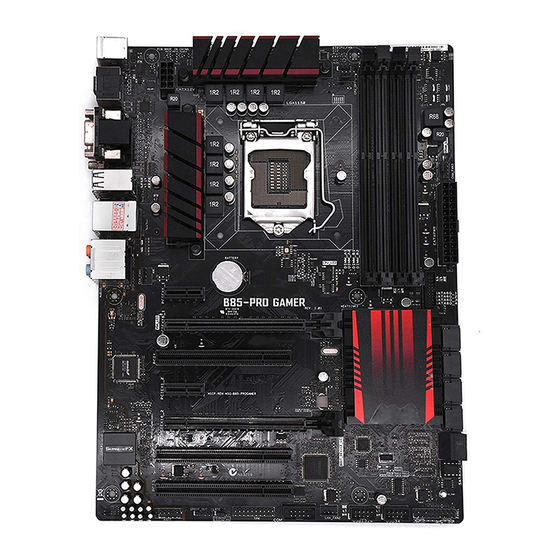
When installing the motherboard, place it into the chassis in the correct orientation. The edge with external ports goes to the rear part of the chassis as indicated in the image. 1.2.2 Screw holes Place six screws into the holes indicated by circles to secure the motherboard to the chassis. Do not overtighten the screws! Doing so can damage the motherboard. ASUS B85-PRO GAMER... -
Page 10: Motherboard Layout
Place this side towards the rear of the chassis 1.2.3 Motherboard layout Chapter 1: Product introduction... -
Page 11: Central Processing Unit (Cpu)
1-25 [black]) 8. Standby Power LED (SB_PWR) 1-27 9. System panel connector (20-8 pin F_PANEL) 1-26 1-24 10. USB 2.0 connectors (10-1 pin USB1314, USB34) 11. Serial port connectors (10-1 pin COM) 1-21 1-22 12. TPM connector (20-1 pin TPM) 13. Clear RTC RAM (3-pin CLRTC) 1-18 1-23 14. Digital audio connector (4-1 pin SPDIF_OUT) 15. Front panel audio connector (10-1 pin AAFP) 1-23 Central Processing Unit (CPU) This motherboard comes with a surface mount LGA1150 socket designed for the Intel ® generation Core™ i7 / Core™ i5 / Core™ i3, Pentium , Celeron processors. ® ® ASUS B85-PRO GAMER... -
Page 12: Installing The Cpu
Unplug all power cables before installing the CPU. • Ensure that you install the correct CPU designed for the LGA1150 socket only. DO NOT install a CPU designed for LGA1155 and LGA1156 sockets on the LGA1150 socket. • Upon purchase of the motherboard, ensure that the PnP cap is on the socket and the socket contacts are not bent. Contact your retailer immediately if the PnP cap is missing, or if you see any damage to the PnP cap/socket contacts/motherboard components. ASUS will shoulder the cost of repair only if the damage is shipment/ transit-related. • Keep the cap after installing the motherboard. ASUS will process Return Merchandise Authorization (RMA) requests only if the motherboard comes with the cap on the LGA1150 socket. • The product warranty does not cover damage to the socket contacts resulting from incorrect CPU installation/removal, or misplacement/loss/incorrect removal of the PnP cap. 1.3.1 Installing the CPU Chapter 1: Product introduction... -
Page 13: Cpu Heatsink And Fan Assembly Installation
1.3.2 CPU heatsink and fan assembly installation Apply the Thermal Interface Material to the CPU heatsink and CPU before you install the heatsink and fan if necessary. ASUS B85-PRO GAMER... - Page 14 To install the CPU heatsink and fan assembly To uninstall the CPU heatsink and fan assembly Chapter 1: Product introduction...
-
Page 15: System Memory
® CPU. 1.4.2 Memory configurations You may install 1 GB, 2 GB, 4 GB, and 8 GB unbuffered non-ECC DDR3 DIMMs into the DIMM sockets. You can refer to the recommended memory population below. • You may install varying memory sizes in Channel A and Channel B. The system maps the total size of the lower-sized channel for the dual-channel configuration. Any excess memory from the higher-sized channel is then mapped for single-channel operation. • Due to Intel chipset limitation, DDR3 1600 MHz and higher memory modules on XMP ® mode will run at the maximum transfer rate of DDR3 1600 MHz. • Always install DIMMs with the same CAS latency. For optimal compatibility, we recommend that you install memory modules of the same version or date code (D/C) from the same vendor. Check with the retailer to get the correct memory modules. • Due to the memory address limitation on 32-bit Windows OS, when you install 4GB ® or more memory on the motherboard, the actual usable memory for the OS can be about 3GB or less. For effective use of memory, we recommend that you do any of the following: Use a maximum of 3 GB system memory if you are using a 32-bit Windows OS. ® I nstall a 64-bit Windows OS if you want to install 4GB or more on the ® motherboard. • This motherboard does not support DIMMs made up of 512 Mb (64 MB) chips or less. ASUS B85-PRO GAMER... -
Page 16: Installing A Dimm
• The default memory operation frequency is dependent on its Serial Presence Detect (SPD), which is the standard way of accessing information from a memory module. • For system stability, use a more efficient memory cooling system to support a full memory load (4 DIMMs). • Visit the ASUS website at www.asus.com for the latest QVL. 1.4.3 Installing a DIMM Unplug the power supply before adding or removing DIMMs or other system components. Failure to do so can cause severe damage to both the motherboard and the components. Press the retaining clip outward to DIMM notch unlock a DIMM socket. Align a DIMM on the socket such that the notch on the DIMM matches the DIMM slot key on the socket. DIMM slot key A DIMM is keyed with a notch so that it fits in only one direction. DO NOT force a DIMM into a socket in the wrong direction to avoid damaging the DIMM. Firmly insert the DIMM into the socket until the retaining clip clicks back in place and the DIMM is properly seated. - Page 17 Support the DIMM lightly with your fingers when pressing the retaining clip. The DIMM might get damaged when it flips out with extra force. Remove the DIMM from the socket. B85-PRO GAMER motherboard Qualified Vendors Lists (QVL) DDR3 2133 MHz capability DIMM socket Chip Chip support Vendors Part No. Size Timing Voltage Brand (Optional) A-DATA AX3U2133W4G10-DR(XMP) 8GB ( 2x 4GB ) 10-11-11-30 1.65 • • A-DATA...
- Page 18 DDR3 1866 MHz capability DIMM socket Chip Chip support Vendors Part No. Size Timing Voltage Brand (Optional) Transcend TX2133KLH-16GK(XMP) 16GB ( 2x 2133-10-11- • • 8GB ) 10-27 Transcend TX2133KLN-8GK(XMP) 8GB ( 2x 2133-10-11- • • 4GB ) 10-27 CORSAIR CMD16GX3M2A1866C9 (Ver5.29)(XMP) 16GB ( 2x 1866 9-9-9-27 • 8GB ) CORSAIR CMD16GX3M4A1866C9 (Ver4.13)(XMP) 16GB ( 4x 9-10-9-27...
- Page 19 8GB ( 2x 9-9-9-24 1.65 (Ver3.19)(XMP) 4GB ) CORSAIR CMZ16GX3M2A1600C10 16GB ( 2x 10⁻¹⁰-10-27 (Ver.3.24)(XMP) 8GB ) CORSAIR CMZ16GX3M4A1600C9(XMP) 16GB ( 4x 9-9-9-24 4GB ) CORSAIR CMZ16GX3M4X1600C9 16GB ( 4x 1600-9-9- (Ver8.16)(XMP) 4GB ) 9-24 CORSAIR CMZ32GX3M4X1600C10 32GB ( 4x 10⁻¹⁰-10-27 (Ver2.2)(XMP) 8GB ) CORSAIR CMZ4GX3M1A1600C9 4GB ( 1x 9-9-9-24 (Ver8.16)(XMP) 4GB ) (continued on the next page) ASUS B85-PRO GAMER 1-11...
- Page 20 DDR3 1600 MHz capability DIMM socket support Vendors Part No. Size Chip Brand Chip NO. Timing Voltage (Optional) 1 / 2 2 / 4 3 / 4 CORSAIR CMZ8GX3M1A1600C10 (Ver3.23) 8GB ( 1x 8GB ) 10-10- (XMP) 10-27 CORSAIR CMZ8GX3M1A1600C10 (Ver8.21) 8GB ( 1x 8GB ) 10-10- (XMP) 10-27 CORSAIR CMZ8GX3M2A1600C8(XMP) 8GB ( 2x 4GB ) 8-8-8-24...
- Page 21 ACT4GHU64B8H1333H 4GB Hynix H5TQ2G83AFR • • • ACTICA ACT4GHU72D8H1333H 4GB Hynix H5TQ2G83AFR(ECC) • • • AE32G1339U1-U 2GB 23EY4587MB3H • • • AE34G1339U2-U 4GB 23EY4587MB3H • • • Apacer 78.A1GC6.9L1 2GB Apacer AM5D5808FEQSBG • • • (continued on the next page) ASUS B85-PRO GAMER 1-13...
- Page 22 DDR3 1333 MHz capability DIMM socket support Chip Vendors Part No. Size Chip NO. Timing Voltage (Optional) Brand Apacer 78.B1GDE.9L10C 4GB Apacer AM5D5908CEHSBG • • • Asint SLA302G08-EDJ1C 2GB ASint 302G08-DJ1C • • • Asint SLZ302G08-EDJ1C 4GB ASint 302G08-DJ1C • •...
- Page 23 20YT3NG 9-9-9- • • • Silicon Power SP004GBLTU133V02 4GB S-POWER 20YT3NG 9-9-9- • • • Team TED34096M1333HC9 4GB Team T3D2568LT-13 • • • Transcend JM1333KLH-8G(623654) Transcend TK963EBF3 • • • Transcend TS1GLK64V3H(620053) MICRON D9QBJ • • • ASUS B85-PRO GAMER 1-15...
-
Page 24: Expansion Slots
Expansion slots In the future, you may need to install expansion cards. The following sub-sections describe the slots and the expansion cards that they support. Unplug the power cord before adding or removing expansion cards. Failure to do so may cause you physical injury and damage motherboard components. 1.5.1 Installing an expansion card To install an expansion card: Before installing the expansion card, read the documentation that came with it and make the necessary hardware settings for the card. Remove the system unit cover (if your motherboard is already installed in a chassis). -
Page 25: Pci Slots
Intel LAN – – – – Shared – – – Shared PCI Slot 1 – – – – – – – PCI Slot 2 Shared – – – – – – – Shared PCI Slot 3 – – – – – – – ASUS B85-PRO GAMER 1-17... -
Page 26: Jumpers
Jumpers Clear RTC RAM (3-pin CLRTC) This jumper allows you to clear the Real Time Clock (RTC) RAM in CMOS. You can clear the CMOS memory of date, time, and system setup parameters by erasing the CMOS RTC RAM data. The onboard button cell battery powers the RAM data in CMOS, which include system setup information such as system passwords. To erase the RTC RAM: Turn OFF the computer and unplug the power cord. Move the jumper cap from pins 1-2 (default) to pins 2-3. Keep the cap on pins 2-3 for about 5-10 seconds, then move the cap back to pins 1-2. Plug the power cord and turn ON the computer. Hold down the <Del> key during the boot process and enter BIOS setup to re- enter data. Except when clearing the RTC RAM, never remove the cap on CLRTC jumper default position. Removing the cap will cause system boot failure! • If the steps above do not help, remove the onboard battery and move the jumper again to clear the CMOS RTC RAM data. After clearing the CMOS, reinstall the battery. • You do not need to clear the RTC when the system hangs due to overclocking. For system failure due to overclocking, use the CPU Parameter Recall (C.P.R.) feature. Shut down and reboot the system, then the BIOS automatically resets parameter settings to default values. 1-18 Chapter 1: Product introduction... -
Page 27: Connectors
LAN port LED indications Activity Link Speed Activity/Link LED Speed LED Status Description Status Description No link 10 Mbps connection Orange Linked ORANGE 100 Mbps connection Orange Data activity GREEN 1 Gbps connection LAN port (Blinking) Orange (Blinking Ready to wake then steady) up from S5 mode ASUS B85-PRO GAMER 1-19... - Page 28 PS/2 keyboard port (purple). This port is for a PS/2 keyboard. HDMI port. This port connects to the tape, CD, DVD player, or other audio sources. DVI-D port. This port is for any DVI-D compatible device. DVI-D can not be converted to output from RGB Signal to CRT and is not compatible with DVI-I. USB 3.0 ports 5 and 6. These two 9-pin Universal Serial Bus (USB) ports are for USB 3.0 devices. • The plugged USB 3.0 device may run on xHCI or EHCI mode, depending on the operating system’s setting. • USB 3.0 devices can only be used for data storage. • We strongly recommend that you connect USB 3.0 devices to USB 3.0 ports for faster and better performance from your USB 3.0 devices. • Due to the design of the Intel 8 series chipset, all USB devices connected to the ® USB 2.0 and USB 3.0 ports are controlled by the xHCI controller. Some legacy USB devices must update their firmware for better compatibility. • Multi-VGA output supports up to three displays under Windows OS environment, two ® displays under BIOS, and one display under DOS. • Intel display architecture design supports the following maximum supported pixel clocks (Pixel Clock = H total x V Total x Frame Rate (Screen refresh rate)): DVI port: 165 MHz...
-
Page 29: Internal Connectors
Serial port connector (10-1 pin COM) This connector is for a serial (COM) port. Connect the serial port module cable to this connector, then install the module to a slot opening at the back of the system chassis. CPU and chassis fan connectors (4-pin CPU_FAN, 4-pin CPU_OPT; CHA_FAN1, CHA_FAN2, CHA_FAN3) Connect the fan cables to the fan connectors on the motherboard, ensuring that the black wire of each cable matches the ground pin of the connector. Do not forget to connect the fan cables to the fan connectors. Insufficient air flow inside the system may damage the motherboard components. These are not jumpers! Do not place jumper caps on the fan connectors! The CPU_FAN connector supports a CPU fan of maximum 1 A (12 W) fan power. ASUS B85-PRO GAMER 1-21... - Page 30 ATX power connectors (24-pin EATXPWR, 8-pin EATX12V) These connectors are for ATX power supply plugs. The power supply plugs are designed to fit these connectors in only one orientation. Find the proper orientation and push down firmly until the connectors completely fit. • For a fully configured system, we recommend that you use a power supply unit (PSU) that complies with ATX 12 V Specification 2.0 (or later version) and provides a minimum power of 350 W. • DO NOT forget to connect the 4-pin/8-pin ATX +12V power plug. Otherwise, the system will not boot up. • We recommend that you use a PSU with higher power output when configuring a system with more power-consuming devices or when you intend to install additional devices. The system may become unstable or may not boot up if the power is inadequate. • If you are uncertain about the minimum power supply requirement for your system, refer to the Recommended Power Supply Wattage Calculator at http://support.asus. com/PowerSupplyCalculator/PSCalculator.aspx?SLanguage=en-us for details. TPM connector (20-1 pin TPM) This connector supports a Trusted Platform Module (TPM) system, which securely store keys, digital certificates, passwords and data. A TPM system also helps enhance the network security, protects digital identities, and ensures platform integrity. 1-22 Chapter 1: Product introduction...
- Page 31 Front panel audio connector (10-1 pin AAFP) This connector is for a chassis-mounted front panel audio I/O module that supports either HD Audio or legacy AC`97 audio standard. Connect one end of the front panel audio I/O module cable to this connector. • We recommend that you connect a high-definition front panel audio module to this connector to avail of the motherboard’s high-definition audio capability. • If you want to connect a high-definition front panel audio module to this connector, set the Front Panel Type item in the BIOS setup to [HD]. If you want to connect an AC’97 front panel audio module to this connector, set the item to [AC97]. By default, this connector is set to [HD]. See section 2.6.7 Onboard Devices Configuration for details. Digital audio connector (4-1 pin SPDIF_OUT) This connector is for an additional Sony/Philips Digital Interface (S/PDIF) port. Connect the S/PDIF Out module cable to this connector, then install the module to a slot opening at the back of the system chassis. The S/PDIF module is purchased separately. ASUS B85-PRO GAMER 1-23...
- Page 32 USB 3.0 connector (20-1 pin USB3_12) This connector allows you to connect a USB 3.0 module for additional USB 3.0 front or rear panel ports. With an installed USB 3.0 module, you can enjoy all the benefits of USB 3.0 including faster data transfer speeds of up to 5 Gbps, faster charging time for USB-chargeable devices, optimized power efficiency, and backward compatibility with USB 2.0. The USB 3.0 module is purchased separately. USB 2.0 connectors (10-1 pin USB1314, USB34) These connectors are for USB 2.0 ports. Connect the USB module cable to any of these connectors, then install the module to a slot opening at the back of the system chassis. These USB connectors comply with USB 2.0 specifications and supports up to 480Mbps connection speed. Never connect a 1394 cable to the USB connectors. Doing so will damage the motherboard! The USB 2.0 module is purchased separately. 1-24 Chapter 1: Product introduction...
- Page 33 B85 Serial ATA 6.0Gb/s connector (7-pin SATA6G_1, SATA6G_2, ® SATA6G_3, SATA6G_4, [gray]) This connector connects to Serial ATA 6.0 Gb/s hard disk drives via Serial ATA 6.0 Gb/s signal cables. When using hot-plug and NCQ, set the SATA Mode Selection item in the BIOS to [AHCI]. See section SATA Configuration for details. Intel B85 Serial ATA 3.0 Gb/s connectors (7-pin SATA3G_5, SATA3G_6 [black]) ® These connectors connect to Serial ATA 3.0 Gb/s hard disk drives and optical drives via Serial ATA 3.0 Gb/s signal cables. When using hot-plug and NCQ, set the SATA Mode Selection item in the BIOS to [AHCI]. See section SATA Configuration for details. ASUS B85-PRO GAMER 1-25...
-
Page 34: System Panel Connector
System panel connector (10-1 pin PANEL) This connector supports several chassis-mounted functions. • System power LED (2-pin PWR_LED) This 2-pin connector is for the system power LED. Connect the chassis power LED cable to this connector. The system power LED lights up when you turn on the system power, and blinks when the system is in sleep mode. • Hard disk drive activity LED (2-pin HDD_LED) This 2-pin connector is for the HDD Activity LED. Connect the HDD Activity LED cable to this connector. The HDD LED lights up or flashes when data is read from or written to the HDD. • System warning speaker (4-pin SPEAKER) This 4-pin connector is for the chassis-mounted system warning speaker. The speaker allows you to hear system beeps and warnings. • ATX power button/soft-off button (2-pin PWR_SW) This connector is for the system power button. -
Page 35: Onboard Leds
Onboard LEDs Standby Power LED (SB_PWR) The motherboard comes with a standby power LED that lights up to indicate that the system is ON, in sleep mode, or in soft-off mode. This is a reminder that you should shut down the system and unplug the power cable before removing or plugging in any motherboard component. The illustration below shows the location of the onboard LED. ASUS B85-PRO GAMER 1-27... -
Page 36: Software Support
Operating Systems (OS). Always install the latest OS version and corresponding updates to maximize the features of your hardware. Motherboard settings and hardware options vary. Refer to your OS documentation for detailed information. 1.9.2 Support DVD information The Support DVD that comes with the motherboard package contains the drivers, software applications, and utilities that you can install to avail all motherboard features. The contents of the Support DVD are subject to change at any time without notice. Visit the ASUS website at www.asus.com for updates. To run the Support DVD Place the Support DVD into the optical drive. If Autorun is enabled in your computer, the DVD automatically displays the lists of the unique features of your ASUS motherboard. Click the Drivers, Utilities, AHCI/RAID Driver, Manual, Contact, or Specials tabs to display their respective menus. The following screen is for reference only. Click an icon to display Support... -
Page 37: Bios Information
DVD and a USB flash disk drive. Save a copy of the original motherboard BIOS file to a USB flash disk in case you need to restore the BIOS in the future. Copy the original motherboard BIOS using the ASUS Update utility. -
Page 38: Asus Ez Flash
2.1.2 ASUS EZ Flash 2 The ASUS EZ Flash 2 feature allows you to update the BIOS without using an OS-based utility. Before you start using this utility, download the latest BIOS file from the ASUS website at www.asus.com. To update the BIOS using EZ Flash 2: Insert the USB flash disk that contains the latest BIOS file to the USB port. -
Page 39: Asus Crashfree Bios 3 Utility
2.1.3 ASUS CrashFree BIOS 3 utility The ASUS CrashFree BIOS 3 is an auto recovery tool that allows you to restore the BIOS file when it fails or gets corrupted during the updating process. You can restore a corrupted BIOS file using the motherboard support DVD or a USB flash drive that contains the updated BIOS file. - Page 40 Boot your computer then press <F8> to launch the BIOS Boot Device Select menu. When the BIOS Boot Device Select Menu appears, insert the Support DVD into the optical drive then select the optical drive as the boot device. Please select boot device: ASUS DVD-E818A6T (4069MB) USB DISK 2.0 (3824MB) UEFI: (FAT) USB DISK 2.0 (3824MB)
- Page 41 DO NOT shut down or reset the system while updating the BIOS to prevent system boot failure. Ensure to load the BIOS default settings to ensure system compatibility and stability. Select the Load Optimized Defaults item under the Exit menu for more information. ASUS B85-PRO GAMER...
-
Page 42: Bios Setup Program
The BIOS setup screens shown in this section are for reference only. Some screen displays may not be the same as what you see on your screen. • Visit the ASUS website at www.asus.com to download the latest BIOS file for this motherboard. •... -
Page 43: Advanced Mode
The Advanced Mode provides advanced options for experienced end-users to configure the BIOS settings. Refer to the following sections for the detailed configurations. To access the EZ Mode, click Exit, then select ASUS EZ Mode or press F7. ASUS B85-PRO GAMER... -
Page 44: Menu Bar
Back button Menu items Menu bar Configuration fields General help Last modified Navigation keys settings Submenu item Pop-up window Scroll bar Quick note Menu bar The menu bar on top of the screen has the following main items: My Favorites For saving the frequently-used system settings and configuration For changing the basic system configuration Main... -
Page 45: My Favorites
This button allows you to enter notes of the activities that you have done in BIOS. Last Modified button This button shows the items that you last modified and saved in BIOS Setup. My Favorites MyFavorites is your personal space where you can easily save and access your favorite BIOS items. ASUS B85-PRO GAMER... -
Page 46: Main Menu
Adding items to My Favorites To add frequently-used BIOS items to My Favorites: Use the arrow keys to select an item that you want to add. When using a mouse, hover the pointer to the item. Press <F4> on your keyboard or right-click on your mouse to add the item to My Favorites page. -
Page 47: Administrator Password
Select the User Password item and press <Enter>. From the Enter Current Password box, key in the current password, then press <Enter>. From the Create New Password box, key in a new password, then press <Enter>. Confirm the password when prompted. ASUS B85-PRO GAMER 2-11... -
Page 48: Ai Tweaker Menu
To clear the user password, follow the same steps as in changing a user password, but press <Enter> when prompted to create/confirm the password. After you clear the password, the User Password item on top of the screen shows Not Installed. Ai Tweaker menu The Ai Tweaker menu items allow you to configure overclocking-related items. - Page 49 [Sync All Cores] Allows you to set CPU Core Ratio settings for all cores. [Per Core] Allows you to set CPU Core Ratio individually. The following two items appear only when you set the CPU Core Ratio to [Sync All Cores] or [Per Core]. ASUS B85-PRO GAMER 2-13...
- Page 50 1-Core Ratio Limit [Auto] Allows you to set the 1-Core Ratio Limit. Select [Auto] to apply the CPU default Turbo Ratio setting or manually assign a 1-Core Ratio Limit value that is higher than or equal to the 2-Core Ratio Limit. 2-Core/3-Core/4-Core Ratio Limit [Auto] These items become configurable only when you set the CPU Core Ratio item to [Per Core].
-
Page 51: Dram Timing Control
Configuration options: [Auto] [1 DRAM Clock] – [16 DRAM Clock] DRAM READ to PRE Time [Auto] Configuration options: [Auto] [1 DRAM Clock] – [15 DRAM Clock] DRAM FOUR ACT WIN Time [Auto] Configuration options: [Auto] [1 DRAM Clock] – [255 DRAM Clock] ASUS B85-PRO GAMER 2-15... - Page 52 DRAM WRITE to READ Delay [Auto] Configuration options: [Auto] [1 DRAM Clock] – [15 DRAM Clock] DRAM CKE Minimum pulse width [Auto] Configuration options: [Auto] [1 DRAM Clock] – [15 DRAM Clock] DRAM CAS# Write Latency [Auto] Configuration options: [Auto] [1 DRAM Clock] – [31 DRAM Clock] RTL IOL control DRAM RTL (CHA_R0D0) [Auto] Configuration options: [Auto] [1] - [63]...
- Page 53 [Auto] Configuration options: [Auto] [1 DRAM Clock] – [31 DRAM Clock] tRDWR_dr [Auto] Configuration options: [Auto] [1 DRAM Clock] – [31 DRAM Clock] tRDWR_dd [Auto] Configuration options: [Auto] [1 DRAM Clock] – [31 DRAM Clock] ASUS B85-PRO GAMER 2-17...
- Page 54 Configuration options: [Enable Both DIMMS] [Disable DIMM0] [Disable DIMM1] [Disable Both DIMMS] Scrambler Setting [Optimized ...] Configuration options: [Optimized (ASUS)] [Default (MRC)] MCH Full Check [Auto] Allows you to enable, disable, or automatically set the MCH Full Check function. Configuration options: [Auto] [Enabled] [Disabled] Skew Control Adjust these items may enhance the DRAM overclocking capability and stability.
- Page 55 Allows you to configure the total power range, and extends the overclocking frequency range simultaneously. Configuration options: [Auto] [100%] [110%] [120%] [130%] [140%] Choose a higher value when overclocking, or under a high CPU loading for extra power support. ASUS B85-PRO GAMER 2-19...
-
Page 56: Cpu Power Management
2.5.12 CPU Power Management The subitems in this menu allow you to set the CPU ratio and features. Enhanced Intel SpeedStep Technology [Enabled] ® Allows you to enable or disable the Enhanced Intel SpeedStep Technology (EIST). ® [Disabled] Disables this function. [Enabled] The operating system dynamically adjusts the processor voltage and core frequency which may result in decreased average consumption and... - Page 57 Use the <+> and <-> keys to adjust the value. Power Saving Level 3 Threshhold [Auto] Allows you to set the power saving level 3 threshhold. Use the <+> and <-> keys to adjust the value. ASUS B85-PRO GAMER 2-21...
- Page 58 2.5.13 Extreme Over-Voltage [Disabled] By default, this item is set to [Disabled] and helps provide over voltage protection for the CPU. When you set this item to [Enabled], you can select voltage settings for overclocking, but this will not guarantee the CPU’s lifespan. 2.5.14 CPU Core Voltage [Auto] This item allows you to set the CPU core voltage.
- Page 59 This item appears only when you set the CPU Graphics Voltage to [Adaptive Mode] and allows you to set the total adaptive mode CPU graphics voltage. The values range from 0.001V to 1.920V with a 0.001V interval. ASUS B85-PRO GAMER 2-23...
- Page 60 2.5.17 CPU System Agent Voltage Offset Mode Sign [+] This item allows you to set the CPU system agent voltage offset mode sign. Configuration options: [+] [-]. CPU System Agent Voltage Offset [Auto] This item allows you to set the CPU system agent voltage offset. Increase the value when increasing DRAM frequency.
- Page 61 Allows you to set the DRAM DATA REF Voltage on CHB. The values range from 0.3950x to 0.6300x with a 0.0050x interval 2.5.28 CPU Spread Spectrum [Auto] [Auto] Automatic configuration. [Disabled] Enhances the BCLK overclocking ability. [Enabled] Sets to [Enabled] for EMI control. ASUS B85-PRO GAMER 2-25...
-
Page 62: Advanced Menu
Advanced menu The Advanced menu items allow you to change the settings for the CPU and other system devices. Be cautious when changing the settings of the Advanced menu items. Incorrect field values can cause the system to malfunction. 2.6.1 CPU Configuration The items in this menu show the CPU-related information that the BIOS automatically detects. - Page 63 Enables the CPU C states. [Disabled] Disables the CPU C states. The following items appear only when you set the CPU C states to [Enabled]. Enhanced C1 state [Enabled] [Enabled] Enables enhanced C1 state. [Disabled] Disables enhanced C1 state. ASUS B85-PRO GAMER 2-27...
-
Page 64: Pch Configuration
CPU C3 Report [Enabled] Allows you to disable or enable the CPU C3 report to OS. Configuration options: [Enabled] [Disabled] CPU C6 Report [Enabled] Allows you to disable or enable the CPU C6 report to OS. Configuration options: [Enabled] [Disabled] C6 Latency [Short] Allows you to choose short or long latency for C6. -
Page 65: Sata Configuration
PCH entering link power state aggressively. Configuration options: [Auto] [Disabled] [Enabled] IDE Legacy / Native Mode Selection [Native] This item appears only when you set the SATA Mode Selection item to [IDE]. Configuration options: [Native] [Legacy] ASUS B85-PRO GAMER 2-29... -
Page 66: System Agent Configuration
S.M.A.R.T. Status Check [Enabled] S.M.A.R.T. (Self-Monitoring, Analysis and Reporting Technology) is a monitor system. When read/write of your hard disk errors occur, this feature allows the hard disk to report warning messages during the POST. Configuration options: [Enabled] [Disabled] Hot Plug [Disabled] (SATA 6G 1~4 [Gray], SATA 3G 5~6 [Black]) These items appear only when you set the SATA Mode Selection item to [AHCI] and allow you to enable/disable SATA Hot Plug Support.Configuration options: [Disabled] [Enabled] 2.6.4... -
Page 67: Dmi Configuration
The USB devices can be used only for the BIOS setup program. [Auto] Allows the system to detect the presence of USB devices at startup. If detected, the USB controller legacy mode is enabled. If no USB device is detected, the legacy USB support is disabled. ASUS B85-PRO GAMER 2-31... -
Page 68: Platform Misc Configuration
Intel xHCI Mode [Smart Auto] ® [Auto] Keeps the last operation of xHCI controller in OS during bootup. [Smart Auto] Enables the operation of xHCI controller. [Enabled] Enables the function. [Disabled] Disables the function. EHCI Hand-off [Disabled] [Enabled] Enables the support for operating systems without an EHCI hand-off feature. -
Page 69: Serial Port Configuration
Sets the Ctrl+Esc key on the PS/2 keyboard to turn on the system. [Power Key] Sets Power key on the PS/2 keyboard to turn on the system. This feature requires an ATX power supply that provides at least 1A on the +5VSB lead. ASUS B85-PRO GAMER 2-33... -
Page 70: Network Stack Configuration
Power On By PS/2 Mouse [Disabled] [Disabled] Disables the Power On by a PS/2 mouse. [Enabled] Enables the Power On by a PS/2 mouse. This feature requires an ATX power supply that provides at least 1A on the +5VSB lead. Power On By PCI-E/PCI [Disabled] [Disabled] Disables the PCI-E/PCI devices to generate a wake-on-LAN feature of the... -
Page 71: Monitor Menu
Monitor menu The Monitor menu displays the system temperature/power status, and allows you to change the fan settings. Scroll down to display the following items: ASUS B85-PRO GAMER 2-35... - Page 72 2.7.1 CPU Temperature [xxx°C/xxx°F] The onboard hardware monitor automatically detects and displays the CPU temperature. Select Ignore if you do not wish to display the detected temperature. 2.7.2 MB Temperature [xxx°C/xxx°F] The onboard hardware monitor automatically detects and displays the mobtherboard temperature.
- Page 73 [Silent] Sets to [Silent] to minimize the fan speed for quiet chassis fan operation. [Turbo] Sets to [Turbo] to achieve maximum chassis fan speed. [Manual] Sets to [Manual] to assign detailed fan speed control parameters. ASUS B85-PRO GAMER 2-37...
- Page 74 The following four items appear only when you set Chassis1/2 Fan Profile to [Manual]. Chassis Fan 1/2/3 Upper Temperature [70] Use the <+> and <-> keys to adjust the upper limit of the Chassis temperature. The values range from 40°C to 75°C. Chassis Fan 1/2/3 Max.
-
Page 75: Boot Menu
Only hard drives connected to SATA ports will be detected during POST. Any hardware change will disable fast boot. [Boot Drive Only] Only boot drive connected to SATA ports will be detected during POST. Any hardware change will disable fast boot. ASUS B85-PRO GAMER 2-39... - Page 76 USB Support [Partial In...] [Disabled] All USB devices will not be available until OS boot up for a fastest POST time. [Full Initialization] All USB devices will be available during POST. This process will extend the POST time. [Partial Initialization] For a faster POST time, only the USB ports with keyboard and mouse connections will be detected.
- Page 77 The following four items appear when you set Launch CSM to [Enabled]. Allows you to select the type of devices that you want to boot up. Configuration options: [UEFI and Legacy OPROM] [Legacy OPROM only] [UEFI only] ASUS B85-PRO GAMER 2-41...
-
Page 78: Secure Boot
Boot from Network Devices [Legacy OPR...] Allows you to select the type of network devices that you want to launch. Configuration options: [Legacy OPROM first] [UEFI driver first] [Ignore] Boot from Storage Devices [Legacy OPR...] Allows you to select the type of storage devices that you want to launch. Configuration options: [Both, Legacy OPROM first] [Both, UEFI first] [Legacy OPROM first] [UEFI driver first] [Ignore] Boot from PCI-E/PCI Expansion Devices [Legacy OPR...]... - Page 79 Load db from File Allows you to load the downloaded db from a USB storage device. Append db from file Allows you to load the additional db from a storage device so that more images can be loaded securely. ASUS B85-PRO GAMER 2-43...
-
Page 80: Boot Option Priorities
• To select the boot device during system startup, press <F8> when ASUS Logo appears. • To access Windows OS in Safe Mode, do any of the following: Press <F5>... -
Page 81: Tool Menu
<Enter> to display the submenu. 2.9.1 ASUS EZ Flash 2 Utility Allows you to run ASUS EZ Flash 2. Press <Enter> to launch the ASUS EZ Flash 2 screen. For more details, see section ASUS EZ Flash 2. 2.9.2 ASUS Overclocking Profile This item allows you to store or load multiple BIOS settings. -
Page 82: Exit Menu
2.9.3 ASUS SPD Information DIMM Slot # [Slot 1] Displays the Serial Presence Detect (SPD) information of the DIMM module installed on the selected slot. Configuration options: [Slot 1] [Slot 2] [Slot 3] [Slot 4] 2.10 Exit menu The Exit menu items allow you to load the optimal default values for the BIOS items, and save or discard your changes to the BIOS items. -
Page 83: Appendices
Cet appareil est conforme aux normes CNR exemptes de licence d’Industrie Canada. Le fonctionnement est soumis aux deux conditions suivantes : (1) cet appareil ne doit pas provoquer d’interférences et (2) cet appareil doit accepter toute interférence, y compris celles susceptibles de provoquer un fonctionnement non souhaité de l’appareil. B85-PRO GAMER... -
Page 84: Canadian Department Of Communications Statement
ASUS Recycling/Takeback Services ASUS recycling and takeback programs come from our commitment to the highest standards for protecting our environment. We believe in providing solutions for you to be able to responsibly recycle our products, batteries, other components as well as the packaging materials. -
Page 85: Asus Contact Information
+1-510-739-3777 +1-510-608-4555 Web site http://usa.asus.com Technical Support Support fax +1-812-284-0883 General support +1-812-282-2787 Online support http://support.asus.com/techserv/techserv.aspx ASUS COMPUTER GmbH (Germany and Austria) Address Harkort Str. 21-23, 40880 Ratingen, Deutschland +49-2102-959931 Web site http://www.asus.de Online contact http://eu-rma.asus.com/sales Technical Support Telephone +49-2102-5789555... - Page 86 Appendices...