Advertisement
STEREO AMPLIFIER
A-407R
THIS MANUAL IS APPLICABLE TO THE FOLLOWING MODEL(S) AND TYPE(S).
Model
Type
A-407R
MY/EW
MY/GR
MV
CONTENTS
1. SAFETY INFORMATION ...................................... 2
2. EXPLODED VIEWS AND PARTS LIST ................ 3
3. SCHEMATIC DIAGRAM ....................................... 6
4. PCB CONNECTION DIAGRAM .......................... 14
5. PCB PARTS LIST ............................................... 19
6. ADJUSTMENT .................................................... 22
PIONEER ELECTRONIC CORPORATION
PIONEER ELECTRONICS SERVICE, INC. P.O. Box 1760, Long Beach, CA 90801-1760, U.S.A.
PIONEER ELECTRONIC (EUROPE) N.V. Haven 1087, Keetberglaan 1, 9120 Melsele, Belgium
PIONEER ELECTRONICS ASIACENTRE PTE. LTD. 501 Orchard Road, #10-00 Wheelock Place, Singapore 238880
c
PIONEER ELECTRONIC CORPORATION 1998
A SPEAKERS B
Power Requirement
AC220 - 230V
AC220 - 230V
AC220 - 230V
4-1, Meguro 1-Chome, Meguro-ku, Tokyo 153-8654, Japan
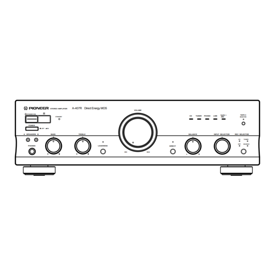
A-407R Direct Energy MOS
STEREO AMPLIFIER
VOLUME
STANDBY/ON
CD
TUNER
PHONO
STANDBY
POWER
OFF
ON
BASS
TREBLE
BALANCE
PHONES
LOUDNESS
DIRECT
MIN
MAX
L
R
7. GENERAL INFORMATION ................................ 23
7.1 IC INFORMATION ....................................... 23
7.2 BLOCK DIAGRAM ....................................... 24
TAPE 2
LINE
TAPE 1
/MD
MONITOR
INPUT SELECTOR
REC SELECTOR
CD
TUNER
ORDER NO.
OFF
SOURCE
RRV1958
Remarks
T - IZK MAY 1998 Printed in Japan
Advertisement
Table of Contents

Related Manuals for Pioneer A-407R


Summary of Contents for Pioneer A-407R
-
Page 1: Table Of Contents
PIONEER ELECTRONICS SERVICE, INC. P.O. Box 1760, Long Beach, CA 90801-1760, U.S.A. PIONEER ELECTRONIC (EUROPE) N.V. Haven 1087, Keetberglaan 1, 9120 Melsele, Belgium PIONEER ELECTRONICS ASIACENTRE PTE. LTD. 501 Orchard Road, #10-00 Wheelock Place, Singapore 238880 PIONEER ELECTRONIC CORPORATION 1998... -
Page 2: Safety Information
The use of a substitute replacement component which does Leakage 0.5mA current Device not have the same safety characteristics as the PIONEER tester under recommended replacement one, shown in the parts list in test this Service Manual, may create shock, fire, or other hazards. -
Page 3: Exploded Views And Parts List
See Contrast table(2) Power Cord See Contrast table(2) Power Cord with Fuse See Contrast table(2) Fuse (T5A) See Contrast table(2) (2) CONTRAST TABLE A-407R/MY/EW, MY/GR and MV are constructed the same except for the following : s i l a i l... - Page 4 A-407R 2.2 EXTERIOR MY/EW, MY/GR Types only...
- Page 5 PCB Holder AEC7057 LED Lens PNW2019 Stud Cover AEC7096 Power Button AAD7436 PCB Mold AMR1525 Screw BMZ30P080FCU Radiator Plate B AMR7223 Locking Card Spacer DEC1908 (2) CONTRAST TABLE A-407R/MY/EW, MY/GR and MV are constructed the same except for the following :...
-
Page 6: Schematic Diagram
A-407R 3. SCHEMATIC DIAGRAM 3.1 OVERALL CONNECTION DIAGRAM HEADPHONE FRONT R ASSY ASSY (AWX7050) (AWX7052) AF ASSY (AWX7053) VOLUME ASSY (AWX7055) - Page 7 A-407R Note : When ordering service parts, be sure to refer to "EXPLODED VIEWS and PARTS LIST" or "PCB PARTS LIST". FRONT L ASSY (AWX7054) AC PRIMARY ASSY POWER SW (MY/EW, MY/GR : AWX7051) ASSY (MV : AWX7056) (AWX7057)
- Page 8 A-407R 3.2 AF ASSY CN501 : AUDIO SIGNAL ROUTE...
- Page 9 A-407R CN601 CN803 AF ASSY (AWX7053) L406 ATX1012...
- Page 10 A-407R 3.3 FRONT L AND VOLUME ASSEMBLIES FRONT L ASSY (AWX7054) FRONT L ASSY S 701 : POWER STANDBY/ON S 702 : LOUDNESS S 703 : SPEAKERS A S 704 : SPEAKERS B...
- Page 11 A-407R VOLUME ASSY (AWX7055) CN203 : AUDIO SIGNAL ROUTE...
- Page 12 A-407R 3.4 FRONT R, AC PRIMARY, HEADPHONE AND POWER SW ASSEMBLIES AC PRIMARY ASSY (MY/EW, MY/GR : AWX7051) (A-407R/MY/EW, MY/GR ONLY) (MV : AWX7056) TO POWER TRANSFORMER T1 T2A L 250V AEK1057 AC POWER CORD • NOTE FOR FUSE REPLACEMENT CAUTION - FOR CONTINUED PROTECTION AGAINST RISK OF FIRE.
- Page 13 A-407R POWER SW ASSY HEADPHONE ASSY (AWX7057) (AWX7052) FRONT R ASSY S 601 : INPUT SELECTOR S 603 : TAPE2 MONITOR S 604 : DIRECT S 606 : REC SELECTOR TC74HC107AP TC74HC00AP...
-
Page 14: Pcb Connection Diagram
A-407R 4. PCB CONNECTION DIAGRAM 4.1 AF ASSY AF ASSY POWER TRANSFORMER CN803 NOTE FOR PCB DIAGRAMS: 1. Part numbers in PCB diagrams match those in the schematic diagrams. 2. A comparison between the main parts of PCB and schematic diagrams is shown below. - Page 15 A-407R Q401 Q406 Q413 Q414 Q451 IC451 IC151 IC452 Q452 IC101 Q409 Q410 Q412 Q411 Q407 Q323 Q408 Q324 Q319 Q101 Q151 Q322 Q104 Q153 VR301 VR302 Q313 Q318 CN601 Q309 Q312 Q325 Q334 IC301 Q301 Q304 Q251 IC251 (ANP7227-A)
- Page 16 A-407R 4.2 FRONT L AND VOLUME ASSEMBLIES FRONT L ASSY (ANP7227-A) VR752 VR751 Q701 Q702 Q704 Q703 Q705 Q707 IC751 Q706 Q751 Q752 SIDE A Q502 Q501 Q503 Q507 Q509 Q506 Q505 CN203 Q504 Q510 Q508 Q513 Q511 Q512 Q514...
- Page 17 A-407R 4.3 FRONT R ASSY FRONT R ASSY Q616 Q606 Q610 Q617 IC603 Q609 Q608 IC602 Q618 Q605 Q604 IC601 Q603 CN202 Q602 VR601 Q601 Q612 Q613 Q611 Q614 Q615 Q607 (ANP7228-A) SIDE A CN701...
- Page 18 A-407R 4.4 AC PRIMARY, HEADPHONE AND POWER SW ASSEMBLIES POWER SW ASSY HEADPHONE ASSY CN401 (ANP7228-A) (ANP7228-A) AC POWER CORD POWER TRANSFORMER LIVE NEUTRAL (ANP7228-A) AC PRIMARY ASSY Q811 IC811 SIDE A E F G...
-
Page 19: Pcb Parts List
A-407R Mark No. Description Part No. Mark No. Description Part No. 5. PCB PARTS LIST • NOTES: Parts marked by "NSP" are generally unavailable because they are not in our Master Spare Parts List. • mark found on some component parts indicates the importance of the safety factor of the part. - Page 20 A-407R Mark No. Description Part No. Mark No. Description Part No. C251 CEAS470M25 FRONT L ASSY C157,C158 CEAS471M6R3 C305,C306,C455,C456 CEBA100M50 SEMICONDUCTORS C463,C464 CEBA100M50 IC751 UPC4570C C405-C407 CEBA2R2M50 Q751,Q752 2SC1845 C301,C302 CEBA3R3M50 Q702,Q703 2SC2458 C317,C318 CEBA470M50 Q701,Q704-Q707 DTC124ES C325,C326 CEBAR47M50 D702,D711...
- Page 21 A-407R Mark No. Description Part No. Mark No. Description Part No. FRONT R ASSY CAPACITORS C801,C802 (0.01µF/AC250V) ACG7020 SEMICONDUCTORS C815 (3.3µF/25V) ACH7027 IC601 PD5369A C813 CEAT471M25 IC603 TC74HC00AP C814 CEBA470M10 IC602 TC74HC107AP C811 CEYANP1R0M50 Q609 2SA1048 RESISTORS Q607,Q610,Q618 2SC2458 All Resistors...
-
Page 22: Adjustment
A-407R 6. ADJUSTMENTS 6.1 IDLE CURRENT ADJUSTMENT ¶ CAUTION : Heatsinks’ (Q323–Q326) DC level is equal to +B or -B. Don’t touch them or you will be electricary chocked. 1. Connect the measuring instrument as Fig.6-1. (R415 or R416) 2. Set the VOLUME CONTROL to minimum, BASS TONE CONTROL to center, TREBLE TONE CONTROL to center and BALANCE CONTROL to center. -
Page 23: General Information
A-407R 7. GENERAL INFORMATION 7.1 IC INFORMATION PD5369A (FRONT R ASSY : IC601) • The information shown in the list is basic information and may not correspond exactly to that shown in the schematic diagrams. • REMOTE CONTROL AMP MICROCOMPUTER •... -
Page 24: Block Diagram
A-407R 7.2 BLOCK DIAGRAM... -
Page 25: Panel Facilities And Specifications
A-407R 8. PANEL FACILITIES AND SPECIFICATIONS 8.1 REAR PANEL Illustration shows U.K. model 2 3 4 5 6 7 8 9 E u r o p e a n model only AC OUTLET SPEAKERS SIGNAL AC INLET PHONO TUNER LINE... -
Page 26: Front Panel
A-407R 8.2 FRONT PANEL A-407R Direct Energy MOS STEREO AMPLIFIER VOLUME Î STANDBY/ON TAPE 2 TAPE 1 TUNER PHONO LINE STANDBY MONITOR POWER A SPEAKERS B BASS TREBLE BALANCE INPUT SELECTOR REC SELECTOR TUNER SOURCE PHONES LOUDNESS DIRECT VOLUME indicator... - Page 27 A-407R REC SELECTOR switch /indicator(For TAPE 1/MD TREBLE tone control Use to adjust the high-frequency tone. The center position is the terminals) flat (normal) position. When turned to the right, the high-frequency This switch is used to select the recording source component.
-
Page 28: Remote Control
When the accessory remote control unit is used to operate other connected to the TAPE 1/MD terminals. PIONEER components with the Î mark, it cannot be used to TAPE 2 : For playback with a cassette deck or adaptor con- operate functions which do not correspond to the functions listed nected to the TAPE 2 MONITOR terminals. -
Page 29: Specifications
A-407R 8.4 SPECIFICATIONS Amplifier Section Signal-to-Noise ratio (IHF short circuit, A network) Continuous power output PHONO (MM, 5 mV input) ..........86 dB* (both channels driven at 20 Hz to 20 kHz)** CD, TUNER, LINE, TAPE 1/MD, T.H.D. 0.06 %, 8 Ω ..........45 W + 45 W* TAPE 2 MONITOR ............