HP ProLiant DL380 Maintenance And Service Manual
Generation 5 server
Hide thumbs
Also See for ProLiant DL380:
- User manual (164 pages) ,
- Quickspecs (60 pages) ,
- Technical white paper (32 pages)

Related Manuals for HP ProLiant DL380


Summary of Contents for HP ProLiant DL380
- Page 1 HP ProLiant DL380 Generation 5 Server Maintenance and Service Guide Part Number 403167-404 July 2010 (Thirteenth Edition)
- Page 2 © Copyright 2006, 2010 Hewlett-Packard Development Company, L.P. The information contained herein is subject to change without notice. The only warranties for HP products and services are set forth in the express warranty statements accompanying such products and services. Nothing herein should be construed as constituting an additional warranty. HP shall not be liable for technical or editorial errors or omissions contained herein.
-
Page 3: Table Of Contents
Contents Customer self repair ........................6 Parts only warranty service ......................... 6 Illustrated parts catalog ....................... 17 Mechanical components ........................... 17 System components ..........................20 Removal and replacement procedures ................... 28 Required tools ............................28 Safety considerations ..........................28 Preventing electrostatic discharge ....................28 Server warnings and cautions ...................... - Page 4 I/O fan bracket ............................69 Cabling ............................. 73 SAS hard drive cabling ..........................73 PCI SAS cabling to an HP Smart Array P400i Controller ..............73 PCI SAS cabling to optional expansion board controller ..............73 Fan board cabling ........................... 74 Hard drive backplane power cabling ......................
- Page 5 Hot-plug power supply calculations ......................96 1.44-MB diskette drive specifications ......................96 CD-ROM drive specifications ........................97 DVD-ROM drive specifications ........................98 SAS and SATA hard drive specifications ....................99 Acronyms and abbreviations ...................... 100 Index ............................102...
-
Page 6: Customer Self Repair
HP specifies in the materials shipped with a replacement CSR part whether a defective part must be returned to HP. In cases where it is required to return the defective part to HP, you must ship the defective part back to HP within a defined period of time, normally five (5) business days. - Page 7 HP sono realizzati con numerosi componenti che possono essere riparati direttamente dal cliente (CSR, Customer Self Repair). Se in fase di diagnostica HP (o un centro di servizi o di assistenza HP) identifica il guasto come riparabile mediante un ricambio CSR, HP lo spedirà direttamente al cliente per la sostituzione.
- Page 8 La mancata restituzione del componente può comportare la fatturazione del ricambio da parte di HP. Nel caso di riparazione da parte del cliente, HP sostiene tutte le spese di spedizione e resa e sceglie il corriere/vettore da utilizzare.
- Page 9 Dokumentation in der Verpackung zurückgeschickt werden, die im Lieferumfang enthalten ist. Wenn Sie das defekte Teil nicht zurückschicken, kann HP Ihnen das Ersatzteil in Rechnung stellen. Im Falle von Customer Self Repair kommt HP für alle Kosten für die Lieferung und Rücksendung auf und bestimmt den Kurier-/Frachtdienst.
- Page 10 Si no enviara el componente defectuoso requerido, HP podrá cobrarle por el de sustitución. En el caso de todas sustituciones que lleve a cabo el cliente, HP se hará cargo de todos los gastos de envío y devolución de componentes y escogerá la empresa de transporte que se utilice para dicho servicio.
- Page 11 HP para que um técnico o ajude por telefone. A HP especifica nos materiais fornecidos com a peça CSR de reposição se a peça com defeito deve ser devolvida à HP. Nos casos em que isso for necessário, é preciso enviar a peça com defeito à HP dentro do período determinado, normalmente cinco (5) dias úteis.
- Page 12 HP fornece as peças de reposição sem cobrar nenhuma taxa. No caso desse serviço, a substituição de peças CSR é obrigatória. Se desejar que a HP substitua essas peças, serão cobradas as despesas de transporte e mão-de-obra do serviço.
- Page 13 Customer self repair 13...
- Page 14 Customer self repair 14...
- Page 15 Customer self repair 15...
- Page 16 Customer self repair 16...
-
Page 17: Illustrated Parts Catalog
Illustrated parts catalog Mechanical components Item Description Assembly Spare part Customer part number number self repair (on page 6) Access panel 394037-001 407744-001 Mandatory Front bezel 394028-003 407745-001 Mandatory Hard drive blank 376383-001 392613-001 Mandatory Media drive blank 377569-001 409006-001 Mandatory Power supply cage assembly 394020-001... - Page 18 Optional—Parts for which customer self repair is optional. These parts are also designed for customer self repair. If, however, you require that HP replace them for you, there may or may not be additional charges, depending on the type of warranty service designated for your product.
- Page 19 Optional: Opcional—Peças cujo reparo feito pelo cliente é opcional. Essas peças também são projetadas para o reparo feito pelo cliente. No entanto, se desejar que a HP as substitua, pode haver ou não a cobrança de taxa adicional, dependendo do tipo de serviço de garantia destinado ao produto.
-
Page 20: System Components
System components Item Description Assembly Spare part Customer part number number self repair (on page 6) System components Hot-plug fan, 60-mm 394035-001 407747-001 Mandatory Processor fan bracket — — — a) Processor fan bracket, 12-fan model 394023-001 408783-001 Mandatory b) Processor fan bracket, 6-fan model* 441011-001 442953-001 Mandatory... - Page 21 Item Description Assembly Spare part Customer part number number self repair (on page 6) I/O fan bracket — — — a) I/O fan bracket, 12-fan model 419315-001 408784-001 Optional b) I/O fan bracket, 6-fan model* 441015-001 442954-001 Optional Power supply —...
- Page 22 Item Description Assembly Spare part Customer part number number self repair (on page 6) k) 1.86-GHz Intel® Xeon® processor 459281-001 460493-001 Optional E5205, dual-core, 1x6-MB L2 cache, 1066- MHz FSB* ** l) 3.33-GHz Intel® Xeon® processor 455302-001 459738-001 Optional X5260, dual-core, 1x6-MB L2 cache, 1333- MHz FSB* ** m) 1.6-GHz Intel®...
- Page 23 Item Description Assembly Spare part Customer part number number self repair (on page 6) HE, quad-core, 2x6-MB L2 cache, 1333- MHz FSB* ** aa) 3.16-GHz Intel® Xeon® processor 455968-001 457879-001 Optional X5460, quad-core, 2x6-MB L2 cache, 1333-MHz FSB* ** bb) 2.66-GHz Intel® Xeon® processor 455292-001 459735-001 Optional...
- Page 24 Item Description Assembly Spare part Customer part number number self repair (on page 6) CD-RW/DVD-ROM drive, slimline, 24X 383696-002 399959-001 Mandatory (optional)* DVD+R/RW drive, slimline, 8X* 395911-001 399402-001 Mandatory Cables Miscellaneous cable kit* — 408795-001 Mandatory a) Power cable, 10-pin 394038-001 —...
- Page 25 HP Smart Array P400 Controller battery 408658-002 409125-001 Mandatory cable assembly, 60.96-cm (24-in)* *Not shown **All processors in this HP ProLiant server must have the same cache size, speed, number of cores, and rated maximum power consumption. Illustrated parts catalog 25...
- Page 26 Optional—Parts for which customer self repair is optional. These parts are also designed for customer self repair. If, however, you require that HP replace them for you, there may or may not be additional charges, depending on the type of warranty service designated for your product.
- Page 27 Optional: Opcional—Peças cujo reparo feito pelo cliente é opcional. Essas peças também são projetadas para o reparo feito pelo cliente. No entanto, se desejar que a HP as substitua, pode haver ou não a cobrança de taxa adicional, dependendo do tipo de serviço de garantia destinado ao produto.
-
Page 28: Removal And Replacement Procedures
Required tools You need the following items for some procedures: • T-10/T-15 Torx screwdriver (included with the server) • HP Insight Diagnostics software ("HP Insight Diagnostics" on page 77) Safety considerations Before performing service procedures, review all the safety information. -
Page 29: Preparation Procedures
Extend the server from the rack (on page 29). If you are performing service procedures in an HP, Compaq branded, telco, or third-party rack cabinet, you can use the locking feature of the rack rails to support the server and gain access to internal components. -
Page 30: Power Down The Server
After performing the installation or maintenance procedure, slide the server back into the rack: Press the server rail-release latches and slide the server fully into rack. WARNING: To reduce the risk of personal injury, be careful when pressing the server rail- release latches and sliding the server into the rack. -
Page 31: Remove The Server From The Rack
The system is now without power. Remove the server from the rack To remove the server from an HP, Compaq branded, telco, or third-party rack: Power down the server (on page 30). Extend the server from the rack (on page 29). -
Page 32: Access Panel
NOTE: To access some components, you may need to remove the cable management arm. To access the product rear panel components, open the cable management arm: Power down the server (on page 30). Swing open the cable management arm. Remove the cables from the cable trough. Remove the cable management arm. -
Page 33: Hot-Plug Sas Hard Drive
CAUTION: To prevent improper cooling and thermal damage, do not operate the server unless all bays are populated with either a component or a blank. Remove the component as indicated. To replace the blank, slide the blank into the bay until it locks into place. Hot-plug SAS hard drive CAUTION: To prevent improper cooling and thermal damage, do not operate the server... -
Page 34: Power Supply Blank
Power supply blank To remove the component: CAUTION: To prevent improper cooling and thermal damage, do not operate the server unless all bays are populated with either a component or a blank. Access the product rear panel (on page 31). Remove the power supply blank. -
Page 35: Dc Power Supply
Remove the hot-plug power supply. WARNING: To reduce the risk of electric shock or damage to the equipment, do not connect the power cord to the power supply until the power supply is installed. To replace the component: Slide the hot-plug power supply into the power supply bay. Connect the power cord to the power supply. - Page 36 To reduce the risk of electric shock, fire, and damage to the equipment, this product must be installed in accordance with the following guidelines: This power supply is intended only for installation in HP servers located in a restricted •...
-
Page 37: Media Drive Or Blank
WARNING: To reduce the risk of injury from electric shock hazards, do not open power supplies. Refer all maintenance, upgrades, and servicing to qualified personnel. CAUTION: Do not run the server with one AC power supply and one DC power supply installed. -
Page 38: Hot-Plug Fan
Remove the component as indicated: To replace the component, slide the component into the bay until it is fully seated. Hot-plug fan The server supports variable fan speeds. The fans operate at minimum speed until a temperature change requires a fan speed increase to cool the server. The server shuts down in the following temperature-related scenarios: •... -
Page 39: Processor Fan Bracket
Remove the access panel ("Access panel" on page 32). Remove the fan. CAUTION: Do not operate the server for long periods with the access panel open or removed. Operating the server in this manner results in improper airflow and improper cooling that can lead to thermal damage. -
Page 40: Front Bezel
Remove the processor fan bracket. Remove all hot-plug fans from the processor fan bracket ("Hot-plug fan" on page 38). To replace the component, reverse the removal steps and press down on the top of each fan to be sure it is seated properly. -
Page 41: Power Supply Cage Assembly
Remove the five T-15 Torx screws and detach the front bezel. To replace the component, reverse the removal procedure. Power supply cage assembly To remove the component: Power down the server (on page 30). Access the product rear panel (on page 31). Remove all power supplies ("Hot-plug power supply"... -
Page 42: Systems Insight Display
Systems Insight Display To remove the component: Power down the server (on page 30). Extend the server from the rack (on page 29). Remove the access panel ("Access panel" on page 32). IMPORTANT: For this procedure, you do not need to remove the hot-plug fans from the processor fan bracket. -
Page 43: Processor Fan Bracket Plate
Remove the fan board. To replace the component, reverse the removal procedure. Processor fan bracket plate To remove the component: Power down the server (on page 30). Extend the server from the rack (on page 29). Remove the access panel ("Access panel"... -
Page 44: Media Drive Ejector Assembly
Remove the processor fan bracket plate. To replace the component, reverse the removal procedure. Media drive ejector assembly To remove the component: Power down the server (on page 30). Extend or remove the server from the rack ("Remove the server from the rack"... -
Page 45: Ppm
Remove the ejector assembly. To replace the component, reverse the removal procedure. To remove the component: Power down the server (on page 30). Extend the server from the rack (on page 29). Remove the access panel ("Access panel" on page 32). NOTE: The appearance of compatible PPMs may vary. -
Page 46: Ppm Retainer
Remove the PPM. IMPORTANT: PPM slots must be populated when processors are installed. If PPM slots are not populated, the server halts during POST or does not boot. To replace the component, reverse the removal procedure. PPM retainer To remove the component: Power down the server (on page 30). -
Page 47: Processor
Remove the PPM retainer. To replace the component, reverse the removal procedure. Processor CAUTION: To avoid damage to the processor and system board, only authorized personnel should attempt to replace or install the processor in this server. IMPORTANT: Processor socket 1 and PPM slot 1 must be populated at all times or the server does not function properly. - Page 48 Open the heatsink retaining bracket. Remove the heatsink. Removal and replacement procedures 48...
- Page 49 Open the processor retaining latch and the processor socket retaining bracket. Using your fingers, remove the failed processor. To replace a processor: IMPORTANT: Be sure the processor remains inside the processor installation tool. Removal and replacement procedures 49...
- Page 50 If the processor has separated from the installation tool, carefully re-insert the processor in the tool. Align the processor installation tool with the socket and install the spare processor. CAUTION: The processor is designed to fit one way into the socket. Use the alignment guides on the processor and socket to properly align the processor with the socket.
- Page 51 Press down firmly until the processor installation tool clicks and separates from the processor, and then remove the processor installation tool. Close the processor retaining latch and the processor socket retaining bracket. Clean the old thermal grease from the heatsink with the alcohol swab. Allow the alcohol to evaporate before continuing.
- Page 52 Apply all the grease to the top of the processor in one of the following patterns to ensure even distribution. Install the heatsink. Removal and replacement procedures 52...
-
Page 53: Battery-Backed Write Cache Procedures
Close and lock the heatsink retaining latches. Install the access panel ("Access panel" on page 32). Install the server into the rack. Power up the server. Battery-backed write cache procedures Two types of procedures are provided for the BBWC option: •... -
Page 54: Removing The Battery Pack
Remove the cache module. To replace the component, reverse the removal procedure. CAUTION: To prevent damage to the cache module during installation, be sure the cache module is fully inserted before pressing down. Removing the battery pack To remove the component: Power down the server (on page 30). -
Page 55: Recovering Data From The Battery-Backed Write Cache
Set up a recovery server station using an identical server model. Do not install any internal drives or BBWC in this server. (HP recommends this option.) Find a server that has enough empty drive bays to accommodate all the drives from the failed server and that meets all the other requirements for drive and array migration. -
Page 56: Fbdimms
Remove all hard drive cables from the air baffle. Remove the air baffle. To replace the component, reverse the removal procedure. FBDIMMs To remove the component: Power down the server (on page 30). Extend or remove the server from the rack ("Remove the server from the rack"... -
Page 57: Memory Options
The Advanced Memory Protection option is configured in RBSU. By default, the server is set to Advanced ECC mode. For more information, see "HP ROM-Based Setup Utility (on page 77)." If the configured AMP mode is not supported by the installed FBDIMM configuration, the system boots in Advanced ECC mode. -
Page 58: Online Spare Memory Configuration
memory errors. Advanced ECC provides additional protection over Standard ECC because it is possible to correct certain memory errors that would otherwise be uncorrectable and result in a server failure. Whereas standard ECC can correct single-bit memory errors, Advanced ECC can correct single-bit memory errors and multi-bit memory errors if all failed bits are on the same DRAM device on the FBDIMM. -
Page 59: Mirrored Memory Configuration
Online spare FBDIMM configuration requirements (in addition to general configuration requirements): • When only bank A is being used, it must be fully populated with dual-rank FBDIMMs. • If banks A and C are being used, they must be fully populated. •... -
Page 60: Power Supply Backplane
Power supply backplane To remove the component: Power down the server (on page 30). Remove all power supplies ("Hot-plug power supply" on page 34). Extend or remove the server from the rack ("Remove the server from the rack" on page 31). Remove the access panel ("Access panel"... -
Page 61: Hard Drive Backplane Retainer
Remove the hard drive backplane. To replace the component, reverse the removal procedure. Hard drive backplane retainer To remove the component: Power down the server (on page 30). Extend or remove the server from the rack ("Remove the server from the rack"... -
Page 62: Pci Riser Cage
PCI riser cage To remove the component: CAUTION: To prevent damage to the server or expansion boards, power down the server and remove all AC power cords before removing or installing the PCI riser cage. Power down the server (on page 30). Extend the server from the rack (on page 29). -
Page 63: Expansion Slot Covers (3, 4, And 5)
Remove the expansion slot cover. To replace the component, reverse the removal procedure. Expansion slot covers (3, 4, and 5) CAUTION: To prevent damage to the server or expansion boards, power down the server and remove all AC power cords before removing or installing the PCI riser cage. CAUTION: To prevent improper cooling and thermal damage, do not operate the server unless all PCI slots have either an expansion slot cover or an expansion board installed. -
Page 64: Expansion Slot Cover Retainer (Slots 1 And 2)
To replace the component, reverse the removal procedure. Expansion slot cover retainer (slots 1 and 2) To remove the component: Power down the server (on page 30). Extend or remove the server from the rack ("Remove the server from the rack"... -
Page 65: Removing Expansion Board (Slots 3, 4, And 5)
Remove the expansion board. CAUTION: To prevent improper cooling and thermal damage, do not operate the server unless all PCI slots have either an expansion slot cover or an expansion board installed. To replace the component, reverse the removal procedure. Removing expansion board (slots 3, 4, and 5) To remove the component: Power down the server (on page 30). -
Page 66: Battery
Remove the expansion board. CAUTION: To prevent improper cooling and thermal damage, do not operate the server unless all PCI slots have either an expansion slot cover or an expansion board installed. To replace the component, reverse the removal procedure. Battery If the server no longer automatically displays the correct date and time, you may need to replace the battery that provides power to the real-time clock. -
Page 67: System Board
Remove the battery. IMPORTANT: Replacing the system board battery resets the system ROM to its default configuration. After replacing the battery, reconfigure the system through RBSU. To replace the component, reverse the removal procedure. For more information about battery replacement or proper disposal, contact an authorized reseller or an authorized service provider. - Page 68 Remove all FBDIMMs ("FBDIMMs" on page 56). Remove the processors. Remove the PPMs ("PPM" on page 45). Disconnect all cables connected to the system board. Identify the eight alignment keys and keyhole locations. Loosen the system board thumbscrew. Remove the system board. Remove the I/O fan bracket ("I/O fan bracket"...
-
Page 69: I/O Fan Bracket
During the server startup sequence, press the F9 key to access RBSU. Select the System Options menu. Select Serial Number. The following warning is displayed: WARNING! WARNING! WARNING! The serial number is loaded into the system during the manufacturing process and should NOT be modified. This option should only be used by qualified service personnel. - Page 70 For ease of removal, invert the system board. To replace the component: Install the I/O fan bracket: 6-fan configuration Removal and replacement procedures 70...
- Page 71 12-fan configuration Secure the I/O fan bracket to the system board. Install the system board. Install the PPMs. Install the FBDIMMs. Install the air baffle. Install the battery pack. Install all hot-plug fans in the I/O fan bracket. Install the processor fan bracket. Install the PCI riser cage.
- Page 72 Install the power supplies. Power up the server. Removal and replacement procedures 72...
-
Page 73: Cabling
Cabling SAS hard drive cabling PCI SAS cabling to an HP Smart Array P400i Controller PCI SAS cabling to optional expansion board controller Cabling 73... -
Page 74: Fan Board Cabling
Fan board cabling Hard drive backplane power cabling Cabling 74... -
Page 75: Media Drive Bay Cabling
Media drive bay cabling Battery cabling for BBWC NOTE: Use the retaining clip to manage excess cable slack. Cabling 75... -
Page 76: Systems Insight Display Cabling
Systems Insight Display cabling Cabling 76... -
Page 77: Diagnostic Tools
Configuring memory options • Language selection For more information on RBSU, see the HP ROM-Based Setup Utility User Guide on the Documentation CD or the HP website (http://www.hp.com/support/smartstart/documentation). HP Insight Diagnostics HP Insight Diagnostics is a proactive server management tool, available in both offline and online versions, that provides diagnostics and troubleshooting capabilities to assist IT administrators who verify server installations, troubleshoot problems, and perform repair validation. -
Page 78: Hp Insight Diagnostics Survey Functionality
For more information, see the Management CD in the HP Insight Foundation suite for ProLiant. Array Diagnostic Utility The HP Array Diagnostics Utility is a web-based application that creates a report of all HP storage controllers and disk drives. This report provides vital information to assist in identifying faults or conditions that may require attention. -
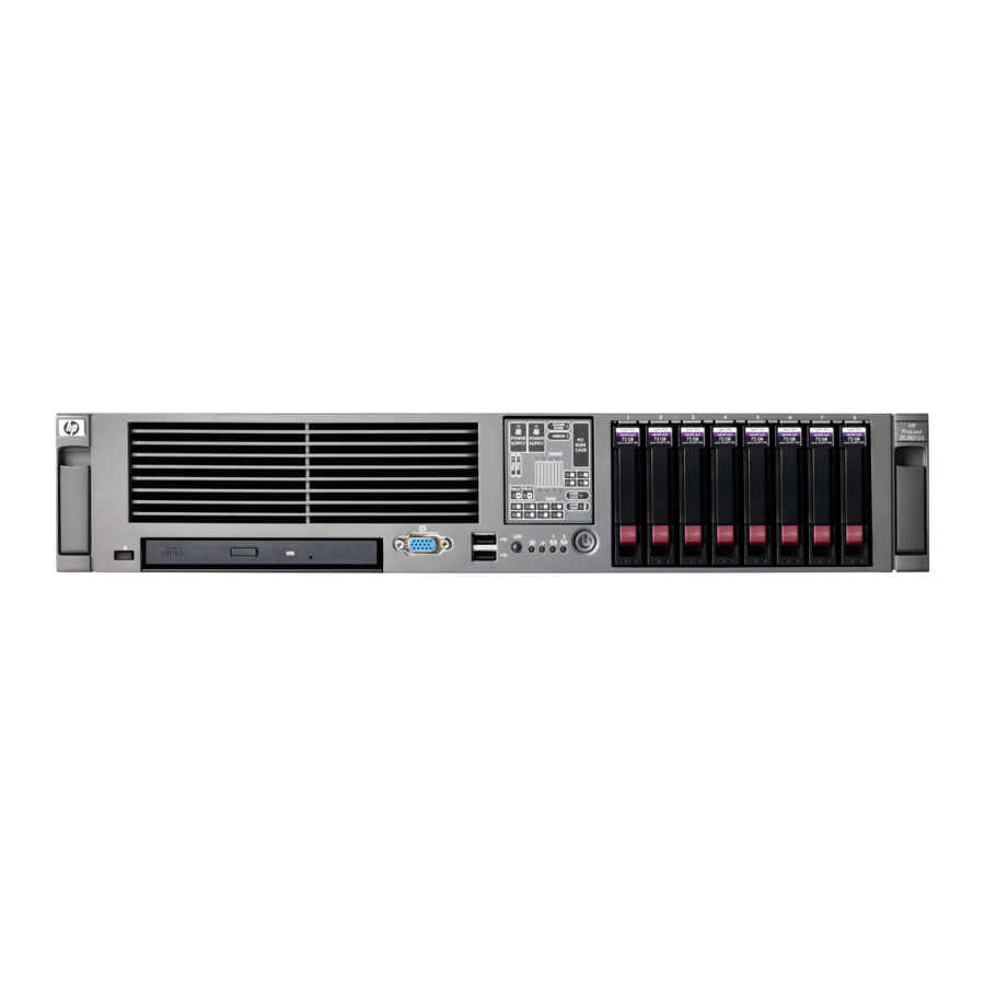
Page 79: Component Identification
Component identification Front panel components Item Description Media drive bay (IDE/diskette multibay) Video connector USB connectors (2) Systems Insight Display Hard drive bays Quick release levers (2) Component identification 79... -
Page 80: Front Panel Leds And Buttons
Front panel LEDs and buttons Item Description Status UID LED button Blue = Activated Flashing = System being remotely managed Off = Deactivated Internal health LED Green = Normal Amber = System degraded. To identify component in degraded state, refer to Systems Insight Display LEDs. Red = System critical. -
Page 81: Systems Insight Display Leds
Test each bank of FBDIMMs by removing all other FBDIMMs. Isolate the failed FBDIMM by replacing each FBDIMM in a bank with a known working FBDIMM. NOTE: The HP Systems Insight Display LEDs represent the system board layout. Component identification 81... -
Page 82: Rear Panel Components
Rear panel components Item Description Color Expansion slot 1 — Expansion slot 2 — Expansion slot 3 — Expansion slot 4 — Expansion slot 5 — T-10/T-15 Torx screwdriver — External option blank — NIC 2 connector — NIC 1 connector —... -
Page 83: Rear Panel Leds And Buttons
Item PCIe Mixed PCIe/PCI-X x4, slot 3, bus C x8, slot 3, bus C x8, slot 4, bus D 64-bit/133-MHz, slot 4, bus D x8, slot 5, bus E 64-bit/133-MHz, slot 5, bus D x4 slots: x8 cards are supported, but will run at x4 speeds. x8 slots: x16 cards are supported, but will run at x8 speeds. -
Page 84: System Board
System board System board components (6-fan configuration) Item Description Fan board connector PPM 1 PPM 2 Power supply backplane connector PCIe slot 1 PCIe slot 2 NMI jumper iLO 2 diagnostic LEDs System maintenance switch Internal USB connector* System battery PCI riser cage connector Fan 2 connector Fan 1 connector... -
Page 85: System Board Components (12-Fan Configuration)
System board components (12-fan configuration) Item Description Fan board connector PPM 1 PPM 2 Power supply backplane connector PCIe slot 1 PCIe slot 2 NMI jumper iLO 2 diagnostic LEDs System maintenance switch Internal USB connector* System battery PCI riser cage connector Fan 4 connector Fan 2 connector Fan 3 connector... -
Page 86: System Maintenance Switch
To force the OS to invoke the NMI handler and generate a crash dump log, the administrator can do any of the following: • Short the NMI jumper pins • Press the NMI switch • Use the iLO Virtual NMI feature For additional information, see the whitepaper on the HP website (http://h20000.www2.hp.com/bc/docs/support/SupportManual/c00797875/c00797875.pdf). Component identification 86... -
Page 87: Fbdimm Slots
FBDIMM slots FBDIMM slots are numbered sequentially (1 through 8) and the paired banks are identified by the letters A, B, C, and D. Systems Insight Display LEDs and internal health LED combinations When the internal health LED on the front panel illuminates either amber or red, the server is experiencing a health event. -
Page 88: Sas Device Numbers
Systems Insight Display Internal health Status LED and color LED color FBDIMM failure, all slots in One or more FBDIMMs has failed. Test each bank of all banks (amber) FBDIMMs by removing all other FBDIMMs. Isolate the failed FBDIMM by replacing each FBDIMM in a bank with a known working FBDIMM. -
Page 89: Sas And Sata Hard Drive Leds
SAS and SATA hard drive LEDs Item Description Fault/UID LED (amber/blue) Online LED (green) SAS and SATA hard drive LED combinations Online/activity Fault/UID LED Interpretation LED (green) (amber/blue) On, off, or Alternating amber The drive has failed, or a predictive failure alert has been flashing and blue received for this drive;... -
Page 90: Pci Riser Cage Led
Online/activity Fault/UID LED Interpretation LED (green) (amber/blue) Flashing The drive is active, and it is operating normally. irregularly Steadily amber A critical fault condition has been identified for this drive, and the controller has placed it offline. Replace the drive as soon as possible. -
Page 91: Battery Pack Leds
A fully- charged battery can normally preserve data for at least two days. The battery lifetime also depends on the cache module size. For further information, refer to the controller QuickSpecs on the HP website (http://www.hp.com). —... -
Page 92: Hot-Plug Fans (6-Fan Configuration)
LED3 pattern LED4 pattern Interpretation — One blink per The battery pack is below the minimum charge level and is being second charged. Features that require a battery (such as write cache, capacity expansion, stripe size migration, and RAID migration) are temporarily unavailable until charging is complete. -
Page 93: Hot-Plug Fans (12-Fan Configuration)
Hot-plug fans (12-fan configuration) For server models that support 12 fans, the fan configuration operates in redundant mode when all 12 fans are installed. Fan board components Item Description Fan connectors (8)* Systems Insight Display connector Power On/Standby button/system power LED UID LED button USB connectors (2) Video connector... - Page 94 *Only the 12-fan configuration supports all connectors. Component identification 94...
-
Page 95: Specifications
Specifications Environmental specifications Specification Value Temperature range* Operating 10°C to 35°C (50°F to 95°F) Shipping -30°C to 50°C (-22°F to 122°F) Storage -30°C to 60°C (-22°F to 140°F) Maximum wet bulb 28°C (82.4°F) temperature Relative humidity (noncondensing)** Operating 10% to 90% Non-operating 5% to 95% * All temperature ratings shown are for sea level. -
Page 96: Fbdimm Specifications
FBDIMMs with identical HP part numbers. *Use only Registered DDR2 FBDIMMs. Use HP FBDIMMs only. Hot-plug power supply calculations For hot-plug power supply specifications and calculators to determine electrical and heat loading for the server, refer to the HP Enterprise Configurator website (http://h30099.www3.hp.com/configurator/). -
Page 97: Cd-Rom Drive Specifications
Specification Value Drive height One-third height Drive rotation 300 rpm Transfer rate High 500 Kb/s 250 Kb/s Bytes/sector Sectors per track (high/low) 18/9 Tracks per side (high/low) 80/80 Access times Track-to-track (high/low) 3 ms/6 ms Average (high/low) 169 ms/94 ms Setting time 15 ms Latency average... -
Page 98: Dvd-Rom Drive Specifications
Specification Value Track pitch 1.6 µm (6.3 × 10 Cache/buffer 128 KB Startup time < 10 s Stop time < 5 s (single); < 30 s (multisession) Laser parameters Type Semiconductor laser GaAs Wave length 700 ± 25 nm Divergence angle 53.5°... -
Page 99: Sas And Sata Hard Drive Specifications
Specification Value Track pitch 0.74 µm (3.15 × 10 in) DVD-ROM 1.6 µm (6.3 × 10 in) CD-ROM Cache/buffer 128 KB Startup time < 15 s Stop time < 5 s (single); < 30 s (multisession) Laser parameters Type Semiconductor laser GaAs Wave length 700 ±... -
Page 100: Acronyms And Abbreviations
Acronyms and abbreviations ABEND abnormal end Automatic Server Recovery BBWC battery-backed write cache double data rate FBDIMM fully buffered DIMM integrated device electronics Integrated Lights-Out Integrated Management Log non-maskable interrupt NVRAM non-volatile memory ORCA Option ROM Configuration for Arrays PCIe peripheral component interconnect express Acronyms and abbreviations 100... - Page 101 PCI-X peripheral component interconnect extended POST Power-On Self Test processor power module RBSU ROM-Based Setup Utility Rapid Deployment Pack serial attached SCSI SATA serial ATA SDRAM synchronous dynamic RAM unit identification universal serial bus VHDCI very high density cable interconnect Acronyms and abbreviations 101...
-
Page 102: Index
LEDs 89 CSR (customer self repair) 6 hard drives 33, 89, 99 customer self repair (CSR) 6 hard drives, determining status of 89 health LEDs 80, 86 HP Insight Diagnostics 77, 78 diagnostic tools 77 diagnostics utility 77 Index 102... - Page 103 I/O fan bracket 69 part numbers 17, 20 illustrated parts catalog 17 PCI riser cage 62 iLO 2 connector 82 PCI slots 64, 65, 82, 83 IML (Integrated Management Log) 78 power cord connector 82 Insight Diagnostics 77, 78 power LEDs, system 80, 82, 91 Integrated Management Log (IML) 78 Power On/Standby button 80 internal health LED 80, 87...
- Page 104 system board components 84, 85 system components 20, 79 system maintenance switch 86 system power LED 80, 91 Systems Insight Display 76, 79 Systems Insight Display cabling 76 telco racks 31 tools 28, 77 Torx screwdriver 82 troubleshooting 77 UID LED 80, 83, 86 USB connectors 79, 82 utilities 77 utilities, deployment 77...