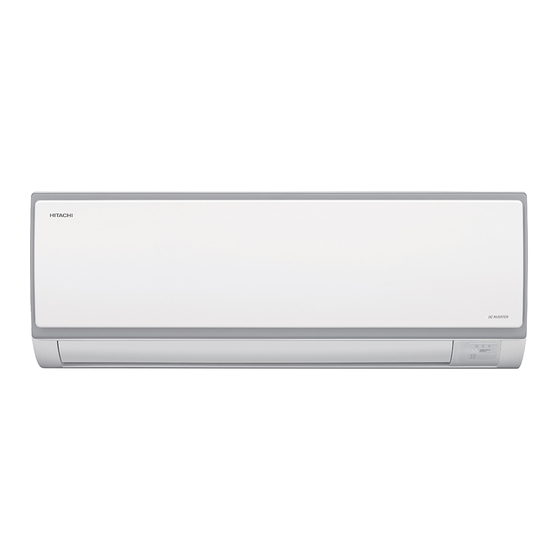
Summary of Contents for Hitachi RPK-0.8FSNQS
- Page 1 RPK-0.8FSNQS RPK-1.0FSNQS Wall- RPK-1.3FSNQS Mounted RPK-1.5FSNQS Type RPK-1.8FSNQS RPK-2.0FSNQS RPK-2.3FSNQS P00611Q ORIGINAL INSTRUCTIONS...
- Page 2 HITACHI HITACHI HITACHI 32DB/23WB...
-
Page 3: Important Notice
To return your used device, please use the return and collection systems or contact the retailer where the product was purchased. They can take this product for environmental safe recycling. HITACHI's HITACHI's... - Page 4 Remote Control Switch Method Setting of Swing Louver Filter Cleaning Taking Out the Filter Cleaning the Filter Reset of Filter Indication Section2 Installation & Maintenance Manual...
- Page 5 Common the Filter Indication Interval...
- Page 6 (×10 Btu/h) Wall-Mounted Type The appliance is not to be used by children or person with reduced physical, sensory or mental capabilities,or lack of experience and knowledge, unless they have been given supervision or instruction concerning use of the appliance by a person responsible for their safety.
- Page 7 Press switches only with fingers. Do not press switches by any other item,as it may break switches.
- Page 8 Regarding the instructions of Wired Remote Control Switch or Wireless Remote Control Switch,read the operation manual attached to the control switch.
- Page 10 approximately...
- Page 11 Users can not change power lines by themselves, replaced by professional maintenance staffs. 2. Necessary Tools and Instrument List for Installation equipments for R410A...
- Page 12 wall and hanging board Accessory Purpose Quantity Mounting For Mounting Indoor Unit Bracket For Mounting Bracket Screw Plate For Drain Hose Setting Thermal For Refrigerant Pipe Insulation Pipe (unit:mm) 1000 Fig. 4.1 Operation and Maintenance Space Fig. 4.2 Hole for Piping on the Wall...
-
Page 13: Drain Hose
(unit:mm) Capacity(HP):0.8/1.0/1.3/1.5 Flange Part for Inserting Suspension Bracket Outline of the Unit Service Space Service Space 37.5 23 42 Unit Exterior Contour (for Pipe and Wiring) (for Pipe and Wiring) Capacity(HP):1.8/2.0/2.3 (unit:mm) 1050 Drain hose Drain hose Fig.4.3 Mounting Bracket... - Page 14 4.3.3 Removing Front Panel 4.3 Installation In order to connect the refrigerant piping, The dimensions of the mounting bracket and the wiring and to check drain water flow, removing unit installation are indicated in Fig. 4.3. the front panel is needed. Perform these work 4.3.1 Mounting Bracket onto Wall according to the following instructions.
- Page 15 (3) There are three stoppers inside of the front (4) Slightly lift the front panel upward in order panel.Check to ensure that there is no gap between to release the combined parts of upper side of the front panel and unit body. front pane Stoppers Any gap will lead to leak or frost.
- Page 16 5.2 Piping Connection (1) Position of piping connection is shown in Figure 5.1 and 5.2. (2) Piping Direction for the Indoor Unit Three directions of piping connection to the indoor unit can be performed; to the rear side, the right When bending the pipes, firmly fix the pipe at side and the left side of the unit, respectively.
-
Page 17: Drain Piping
(3) When tightening the flare nut, use two (7) Fix the plate of pipes (factory-supplied) as spanners as shown in Fig. 5.3 shown in Fig. 5.6. Stopper Pipe diameter Torque (N m) Plate for Pipe Fig. 5.6 Fig.5.3 Tightening Work of Flare Nut Drain Piping (4) Insulate the refrigerant pipes as shown in Fig. - Page 18 (4) Provide a vinyl chloride pipe, VP20. (5) Connect a drain piping as shown in Fig. 6.3. Use adhesive tape for connecting the drain pipe. Provide a downward slope to flow drain water smoothly Use Adhesive Tape Fig. 6.3 Connection of Drain Piping (6) Pour water into the drain pan and check to ensure that water can flow smoothly.
- Page 19 7.1 General Check Electrical Box Cover (1) Make sure that the field-supplied electrical (Opening this cover, PCB1 is in it.) components (main power switches, circuit breakers, wires, conduit connectors and wire terminals) have Wireless been properly selected according to the electrical Terminal Receiver Part Board...
-
Page 20: Indoor Unit
Indoor Unit 0.8~2.3 Model For Control Circuit Fuse Capacity Freeze Protection Cut-Out Thermostat Cut-In Thermostat Differential... - Page 21 10.1 Field Minimum Wire Sizes for Power Souce The wire sizes marked with *1 in the above table are selected at the maximum current of the unit according to the European Standard, EN60335-1.Use the wires which are not lighter than the ordinary polyvinyl chloride sheathed flexible cord (code designation H05VV-F).
- Page 22 10.2 Setting of Dip Switches Horsepower (A) Position of Dip Switches Setting Position 1 2 3 4 1 2 3 4 1 2 3 4 1 2 3 4 DSW2 DSW3 Horsepower PSW301 Receiver Kit DSW5 Setting Position 1 2 3 4 1 2 3 4 1 2 3 4 RSW2...
- Page 23 10.3 Setting the Filter Indication Interval The FILTER indication interval on the remote Step 3 control switch (PC-AR) can be set approximately Optional Setting Items and Changing Setting 100, 1,200 or 2,500 hours (factory setting: 200 Conditions hours). If 100, 1,200 or 2,500 hours interval is The indication of optional setting is as shown required, follow the instructions below.
- Page 24 Qingdao Hisense Hitachi Air Conditioning Systems Co.,LTD. P00611Q 2013.10...


