
Related Manuals for Toshiba PORTEGE R830


Summary of Contents for Toshiba PORTEGE R830
- Page 1 Toshiba Personal Computer PORTEGE R830 Satellite R830 Maintenance Manual First edition January 2011 TOSHIBA CORPORATION File Number 960-880 [CONFIDENTIAL]...
- Page 2 © 2011 by Toshiba Corporation. All rights reserved. Under the copyright laws, this manual cannot be reproduced in any form without the prior written permission of Toshiba. No patent liability is assumed with respect to the use of the information contained herein.
- Page 3 NOTE: “Note” contains general information that relates to your safe maintenance service. Improper repair of the computer may result in safety hazards. Toshiba requires service technicians and authorized dealers or service providers to ensure the following safety precautions are adhered to strictly.
- Page 4 Handling the LCD module Board layout Pin assignments Keyboard scan/character codes Key layout Wiring diagrams BIOS rewrite procedures EC/KBC rewrite procedures Reliability iv PORTEGE R830 Satellite R830 Series Maintenance Manual (960-880) [CONFIDENTIAL]...
- Page 5 Text that you are instructed to type in is shown in the boldface type below: DISKCOPY A: B: The display Text generated by the computer that appears on its display is presented in the type face below: Format complete System transferred PORTEGE R830 Satellite R830 Series Maintenance Manual (960-880) [CONFIDENTIAL]...
-
Page 6: Table Of Contents
3.5-inch Floppy Disk Drive (USB External) .............. 18 HDD&SSD ......................... 19 Optical Drive (ODD) ....................22 Keyboard........................24 TFT Color Display...................... 25 Power Supply ......................26 Batteries ........................28 1.10 AC Adapter ......................... 31 vi PORTEGE R830 Satellite R830 Series Maintenance Manual (960-880) [CONFIDENTIAL]... - Page 7 SD Card Slot Troubleshooting................. 2-54 2.16 PCI ExpressCard Slot Troubleshooting ..............2-56 2.17 Fingerprint sensor Troubleshooting................. 2-57 2.18 Web camera Troubleshooting .................. 2-61 2.19 3G Troubleshooting ....................2-63 2.20 HDMI Troubleshooting ................... 2-65 PORTEGE R830 Satellite R830 Series Maintenance Manual (960-880) [CONFIDENTIAL]...
- Page 8 Wireless LAN Test Program on DUT PC (Intel-made)........... 3-78 3.29 LAN/Modem/Bluetooth/IEEE1394 Test Program ..........3-82 3.30 Sound Test program....................3-89 3.31 SETUP ........................3-90 3.32 Maintenance (WinPE&FreeDos) Test Program Operation ........3-98 viii PORTEGE R830 Satellite R830 Series Maintenance Manual (960-880) [CONFIDENTIAL]...
- Page 9 4.16 Fin ..........................4-49 4.17 Bluetooth module......................4-51 4.18 System board....................... 4-53 4.19 Sound board ........................ 4-62 4.20 Speaker........................4-68 4.21 DC-IN harness ......................4-71 4.22 Touch pad/Fingerprint sensor board ................4-72 PORTEGE R830 Satellite R830 Series Maintenance Manual (960-880) [CONFIDENTIAL]...
- Page 10 Keyboard Scan/Character Codes ..............D-1 Appendix E Key Layout.....................E-1 Appendix F Wiring Diagrams.................... F-1 Appendix G BIOS rewrite Procedures ................G-1 Appendix H EC/KBC rewrite Procedures ................. H-1 Appendix I Reliability......................I-1 x PORTEGE R830 Satellite R830 Series Maintenance Manual (960-880) [CONFIDENTIAL]...
-
Page 11: Chapter 1 Hardware Overview
1 Hardware Overview Chapter 1 Hardware Overview PORTEGE R830 Satellite R830 Series Maintenance Manual (960-880) [CONFIDENTIAL]... - Page 12 1 Hardware Overview [CONFIDENTIAL] PORTEGE R830 Satellite R830 Series Maintenance Manual (960-880)
- Page 13 1.7.1 LCD Module..................25 Power Supply ......................26 Batteries ........................28 1.9.1 Main Battery..................28 1.9.2 Battery Charging Control ..............29 1.9.3 RTC battery ................... 30 1.10 AC Adapter ......................... 31 PORTEGE R830 Satellite R830 Series Maintenance Manual (960-880) [CONFIDENTIAL]...
- Page 14 Table 1-9 Battery specifications .................... 28 Table 1-10 Time required for charges ................... 29 Table 1-11 Data preservation time..................30 Table 1-12 RTC battery charging/data preservation time ............. 30 Table 1-13 AC adapter specifications..................31 [CONFIDENTIAL] PORTEGE R830 Satellite R830 Series Maintenance Manual (960-880)
-
Page 15: Features
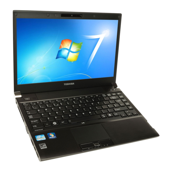
1 Hardware Overview Features The Toshiba PORTEGE R830 Satellite R830 Series Personal Computer uses extensive Large Scale Integration (LSI), and Complementary Metal-Oxide Semiconductor (CMOS) technology extensively to provide compact size, minimum weight, low power usage and high reliability. This computer incorporates the following features. - Page 16 1 Hardware Overview Chipset Toshiba PORTEGE R830 Satellite R830 Series computer is Equipped with Intel Cougar Point QM67 (AMT model) or HM65 (Non-AMT model). VGA Controller The PC comes in with one of the following types: The internal graphics controller in Intel Processor (Core i*) is used.
- Page 17 The USB 2.0 port is compliant with USB 2.0 standard and not compatible with USB 3.0 devices. The USB 3.0 port is compliant with USB 3.0 standard and backward compatible with USB 2.0 devices. PORTEGE R830 Satellite R830 Series Maintenance Manual (960-880) [CONFIDENTIAL]...
- Page 18 Some models are equipped with a Smart Card slot. Fingerprint sensor(Some models) The computer is equipped with a fingerprint sensor and fingerprint authentication utility. They enable only person who has registered his/her fingerprint to use the computer. [CONFIDENTIAL] PORTEGE R830 Satellite R830 Series Maintenance Manual (960-880)
- Page 19 External microphone jack External Headphone jack Docking interface port The docking interface port enables connection of an optional TOSHIBA Hi-Speed Port ReplicatorsⅡ. It provides additional features as follows: RJ45 LAN jack External monitor port DC IN 19V jack ...
- Page 20 Web Camera is a device that allows you to record video or take photographs with your computer. You can use it for video chatting or video conferences using a communication tool such as Windows Live Messenger. TOSHIBA Web Camera Application will help you to add various video effects to your video or photograph.
-
Page 21: Figure 1-1 Front Of The Computer
1 Hardware Overview Figure 1-1 Front of the computer PORTEGE R830 Satellite R830 Series Maintenance Manual (960-880) [CONFIDENTIAL] 1-11... -
Page 22: Figure 1-2 System Unit Configurations
1 Hardware Overview The system unit configuration is shown in figure 1-2 Figure 1-2 System unit configurations 1-12 [CONFIDENTIAL] PORTEGE R830 Satellite R830 Series Maintenance Manual (960-880) -
Page 23: System Unit Block Diagram
1 Hardware Overview System Unit Block Diagram Figure 1-3 is a block diagram of the system unit. Figure 1-3 System unit block diagram PORTEGE R830 Satellite R830 Series Maintenance Manual (960-880) [CONFIDENTIAL] 1-13... - Page 24 1 Hardware Overview The system unit is composed of the following major components: Microprocessor The Toshiba PORTEGE R830 Satellite R830 Series computer is equipped with an ® Intel Processor. The PC comes in with one of the following speeds:...
- Page 25 Atheros 802.11(b/g)WB195-HMC w/ BT V3.0+HS Intel 802.11(b/g/n)13ch-CP 1x2 MOW-HMC Intel a/b/n(2x2) RP2 MOW-HMC w/ BT V3.0+EDR Intel a/g/n(2x2) TP MOW-HMC Intel 802.16e(a/g/n)13ch+WiMAX-KP 2x2 MOW-HMC(BestBuy) Intel 802.16e(b/g/n)WiMAX KelseyPeak WOWL support (only Intel module) PORTEGE R830 Satellite R830 Series Maintenance Manual (960-880) [CONFIDENTIAL] 1-15...
- Page 26 Camera It is BTO correspondence by the built-in microphone and a set. Connection interface: USB I/F connection Product made from Liteon Resolution :VGA Other chips 1-16 [CONFIDENTIAL] PORTEGE R830 Satellite R830 Series Maintenance Manual (960-880)
- Page 27 Use it as a LCD opening-and-closing sensor (ferrite magneto system). Acceleration sensor : Made by ST Microelectronics TSH35TR (Three axes) HDD protection Fingerprint sensor : Made by Authen Tec. It mounts between the Touchpad buttons. PORTEGE R830 Satellite R830 Series Maintenance Manual (960-880) [CONFIDENTIAL] 1-17...
-
Page 28: Inch Floppy Disk Drive (Usb External)
TEAC FD-05PUB-337 (G8AC0000B320) Items 720KB mode 1.44MB mode Data transfer rate FDD part 250K bits/second 500K bits/second Full speed mode (12M bits/second) Disk rotation speed 300rpm Track density 5.3 track/mm (135TPI) 1-18 [CONFIDENTIAL] PORTEGE R830 Satellite R830 Series Maintenance Manual (960-880) -
Page 29: Hdd&Ssd
500GB 320GB (formatted) Speed (RPM) 5,400 7,200 Data transfer rate -/875 1245 1334 Disk-buffer to/from media(Mbps) 3.0/1.5 max. Buffer-host data transfer (Ggit/sec) 3.0 max. Data buffer size 8 MB/s 16MB/s PORTEGE R830 Satellite R830 Series Maintenance Manual (960-880) [CONFIDENTIAL] 1-19... -
Page 30: Table 1-3 2.5-Inch Hdd Specifications (Tsdc)
500GB 640GB Speed (RPM) 5,400 Internal transfer speed 464-1148 typ (Mb/s) Host transfer rate (Gbit/sec) Data buffer size (MB/s) Positioning Time(read Read: 12ms and seek time) Motor startup time (s) 1-20 [CONFIDENTIAL] PORTEGE R830 Satellite R830 Series Maintenance Manual (960-880) -
Page 31: Table 1-4 1.8-Inch Solid State Drive (Ssd) Specifications
(mm) Weigh t (g) Storage size (formatted) 128GB 256GB 512GB Data transfer speed Host Interface : Max 300MB/s Sustained Data Read : Max 250MB/s Sustained Data Write : Max 160MB/s PORTEGE R830 Satellite R830 Series Maintenance Manual (960-880) [CONFIDENTIAL] 1-21... -
Page 32: Optical Drive (Odd)
4 speed (maximum) 8 speed (maximum) DVD+RW write DVD-RAM write 5 speed (maximum) CD-R write 24 speed (maximum) CD-RW write 16 speed (maximum, Ultra-speed media) 150MByte/s SATA interface Data Buffer Capacity 1-22 [CONFIDENTIAL] PORTEGE R830 Satellite R830 Series Maintenance Manual (960-880) - Page 33 Supported Formats CD: CD-DA, CD-ROM, CD-ROM XA, PHOTO CD, CD-Extra(CD+), CD-text, Video CD DVD: DVD-R, DVD-RW (Ver. 1.1, 1.2), DVD-Video, DVD+R, DVD+RW, DVD-RAM,DVD-ROM DVD-R DL(Read only, DVD+R DL(Read only PORTEGE R830 Satellite R830 Series Maintenance Manual (960-880) [CONFIDENTIAL] 1-23...
-
Page 34: Keyboard
JIS. The keyboard is connected to membrane connector on the system board and controlled by the keyboard controller. Figure 1-6 is a view of the keyboard. See Appendix E about a layout of the keyboard. Figure 1- 6 Keyboard 1-24 [CONFIDENTIAL] PORTEGE R830 Satellite R830 Series Maintenance Manual (960-880) -
Page 35: Tft Color Display
13.3 HD 200 CSV LD G33C00068110 G33C00067110 1,366 (W) x 768 (H) Number of Dots 0.2148(H)x0.2148(V) Dot pitch (mm) 293.42(H)x164.97(V) (13.3”diagonal) Active area (mm) 306.3(W) × 177.7(H) × 3.6(D) Outline (mm) PORTEGE R830 Satellite R830 Series Maintenance Manual (960-880) [CONFIDENTIAL] 1-25... -
Page 36: Power Supply
6. Provides more accurate detection of a low battery. 7. Calculates the remaining battery capacity. 8. Controls the transmission of the status signal of the main battery. The power supply output rating is specified in Table 1-8 1-26 [CONFIDENTIAL] PORTEGE R830 Satellite R830 Series Maintenance Manual (960-880) -
Page 37: Table 1-8 Power Supply Output Rating
1 Hardware Overview Table 1-7 Power supply output rating PORTEGE R830 Satellite R830 Series Maintenance Manual (960-880) [CONFIDENTIAL] 1-27... -
Page 38: Batteries
The removable main battery pack is the computer’s main power source when the AC adaptor is not attached. The main battery maintains the state of the computer when the computer enters in sleep mode. 1-28 [CONFIDENTIAL] PORTEGE R830 Satellite R830 Series Maintenance Manual (960-880) -
Page 39: Table 1-10 Time Required For Charges
If any of the following occurs, the battery charge process stops. 1. The battery becomes fully charged. 2. The AC adaptor or battery is removed. 3. The battery or output voltage is abnormal. PORTEGE R830 Satellite R830 Series Maintenance Manual (960-880) [CONFIDENTIAL] 1-29... -
Page 40: Table 1-11 Data Preservation Time
Table 1-12 lists the charging time and data preservation period of the RTC battery. Table 1-11 RTC battery charging/data preservation time Status Time Charging Time (power on) 10 hours Data preservation period (full charge) 30 days 1-30 [CONFIDENTIAL] PORTEGE R830 Satellite R830 Series Maintenance Manual (960-880) -
Page 41: Ac Adapter
Table 1-12 AC adapter specifications Parameter Specification G71C0009S210/ G71C0009S111 / G71C000AE212 (2-pin) G71C000AE113 (3-pin) Power Input voltage 100V/240V Input frequency 50Hz to 60Hz Input current 1.5 A (100V-240V) B Output voltage Output current 3.42A PORTEGE R830 Satellite R830 Series Maintenance Manual (960-880) [CONFIDENTIAL] 1-31... -
Page 42: Chapter 2 Troubleshooting Procedures
Troubleshooting Procedures Chapter 2 Troubleshooting Procedures PORTEGE R830 Satellite R830 Series Maintenance Manual (960-880) [CONFIDENTIAL]... - Page 43 Troubleshooting Procedures PORTEGE R830 Satellite R830 Series Maintenance Manual (960-880) [CONFIDENTIAL]...
- Page 44 Procedure 1 Diagnostic Test Program Execution Check....2-40 2.7.2 Procedure 2 Connector Check and Replacement Check.....2-40 Touch pad Troubleshooting ..................2-41 2.8.1 Procedure 1 Diagnostic Test Program Execution Check....2-41 2.8.2 Procedure 2 Connector Check and Replacement Check.....2-41 PORTEGE R830 Satellite R830 Series Maintenance Manual (960-880) [CONFIDENTIAL]...
- Page 45 2.18.1 Procedure 1 Check on Windows OS...........2-61 2.18.2 Procedure 2 Connector Check and Replacement Check.....2-61 2.19 3G Troubleshooting ....................2-63 2.20 HDMI Troubleshooting ..................2-65 2.20.1 Procedure 1 Check on HDMI TV ............2-65 PORTEGE R830 Satellite R830 Series Maintenance Manual (960-880) [CONFIDENTIAL]...
- Page 46 Table 2-2 DC IN icon ......................2-14 Table 2-3 Error code......................2-16 Table 2-4 Debug port error status (1/2) pending ..............2-26 Table 2-5 FDD error code and status...................2-32 Table 2-6 2.5” Hard disk drive error code and status............2-38 PORTEGE R830 Satellite R830 Series Maintenance Manual (960-880) [CONFIDENTIAL]...
-
Page 47: Troubleshooting
2. Implements for debugging port check Toshiba MS-DOS system FD RS-232C cross cable Test board with debug port test cable PC for displaying debug port test result PORTEGE R830 Satellite R830 Series Maintenance Manual (960-880) [CONFIDENTIAL]... - Page 48 There are following two types of connections in the figure of board and module connection in and after 2.3 Power Supply Troubleshooting. (1) Cable connection is described in the figure as line. (2) Pin connection is described in the figure as arrow. <e.g> Connection of modem PORTEGE R830 Satellite R830 Series Maintenance Manual (960-880) [CONFIDENTIAL]...
-
Page 49: Troubleshooting Flowchart
Before going through the flowchart steps, verify the following: Ask him or her to enter the password if a password is registered. Verify with the customer that Toshiba Windows is installed on the hard disk. Non- Windows operating systems can cause the computer to malfunction. - Page 50 Troubleshooting Procedures Figure 2-1 Troubleshooting flowchart (1/2) PORTEGE R830 Satellite R830 Series Maintenance Manual (960-880) [CONFIDENTIAL]...
- Page 51 Troubleshooting Procedures Insert the diagnostic disk into the ODD. Then hold down the C key and start the computer to run the diagnostic test program. Figure 2-1 Troubleshooting flowchart (2/2) 2-10 PORTEGE R830 Satellite R830 Series Maintenance Manual (960-880) [CONFIDENTIAL]...
- Page 52 13. If an error is detected on the sound test, perform the SD Card Troubleshooting Procedures in Section 2.15. 14. If a malfunction is detected on the PCI ExpressCard, perform the PCI ExpressCard Troubleshooting Procedures in Section 2.16. 2-11 PORTEGE R830 Satellite R830 Series Maintenance Manual (960-880) [CONFIDENTIAL]...
- Page 53 17. If a malfunction is detected on the 3G, perform the 3G Troubleshooting Procedures in Section 2.19 18. If a malfunction is detected on the HDMI, perform the HDMI Troubleshooting Procedures in Section 2.20 2-12 PORTEGE R830 Satellite R830 Series Maintenance Manual (960-880) [CONFIDENTIAL]...
-
Page 54: Power Supply Troubleshooting
(even intervals) Blinks orange once The system is driven by only a battery and the battery level (at being switched on) is low. Doesn’t light Any condition other than those above. 2-13 PORTEGE R830 Satellite R830 Series Maintenance Manual (960-880) [CONFIDENTIAL]... - Page 55 Check 2 If the DC IN icon does not light, go to Procedure 3. Check 3 If the battery icon does not light orange or blue, go to Procedure 4. NOTE: Use a supplied AC adapter G71C000A5210 (2-pin)/ G71C000A6210 (3-pin). 2-14 PORTEGE R830 Satellite R830 Series Maintenance Manual (960-880) [CONFIDENTIAL]...
-
Page 56: Procedure 2 Error Code Check
On for half second Interval between data bits Off for half second The error code begins with the least significant digit. Example: Error code 11h (Error codes are given in hexadecimal format.) Start 2-15 PORTEGE R830 Satellite R830 Series Maintenance Manual (960-880) [CONFIDENTIAL]... - Page 57 Current from the DC power supply is over 6.6A. Current from the DC power supply is over 0.5A when there is no load. The compensation value of [0A] is not within the limits from design data (± 481mA). 2-16 PORTEGE R830 Satellite R830 Series Maintenance Manual (960-880) [CONFIDENTIAL]...
-
Page 58: Main Battery
E5V voltage is under 4.50V when the computer is powered on. E5V voltage is under 4.50V when the computer is booting up. E5V voltage is under 4.50V when EV power is maintained. 2-17 PORTEGE R830 Satellite R830 Series Maintenance Manual (960-880) [CONFIDENTIAL]... -
Page 59: E3V Output
1R05-E1V voltage is under 0.89V when the computer is powered on. 1R05-E1V voltage is under 0.89V when the computer is booting up. 1R05-E1V voltage is under 0.89V when EV power is maintained. 2-18 PORTEGE R830 Satellite R830 Series Maintenance Manual (960-880) [CONFIDENTIAL]... -
Page 60: Igd-Pgv Output
PGV voltage is under 0.00V when the computer is powered on. PGG voltage is under 0.00V when the computer is booting up. Miscellaneous Error code Meaning The sub clock does not oscillate. 2-19 PORTEGE R830 Satellite R830 Series Maintenance Manual (960-880) [CONFIDENTIAL]... -
Page 61: Procedure 3 Connection Check
Check 3 Make sure the battery pack is installed in the computer correctly. If the battery is properly installed and the battery icon still does not light, go to Procedure 4. 2-20 PORTEGE R830 Satellite R830 Series Maintenance Manual (960-880) [CONFIDENTIAL]... -
Page 62: Procedure 4 Charging Check
Battery pack may be faulty. Replace it with a new one. If the problem still occurs, perform Check 2. Check 2 System board may be faulty. Replace it with a new one. 2-21 PORTEGE R830 Satellite R830 Series Maintenance Manual (960-880) [CONFIDENTIAL]... -
Page 63: System Board Troubleshooting
Procedure 1 and continue with the other procedures as instructed. The procedures described in this section are: Procedure 1: Message Check Procedure 2: Debugging Port Check Procedure 3: Diagnostic Test Program Execution Check Procedure 4: Replacement Check 2-22 PORTEGE R830 Satellite R830 Series Maintenance Manual (960-880) [CONFIDENTIAL]... -
Page 64: Procedure 1 Message Check
The following error message appears when data stored in RAM under the resume function is lost because the battery has become discharged or the system board is damaged. Go to Procedure 3. WARNING: RESUME FAILURE. PRESS ANY KEY TO CONTINUE. 2-23 PORTEGE R830 Satellite R830 Series Maintenance Manual (960-880) [CONFIDENTIAL]... - Page 65 (17) PIC #2 ERROR (18) KBC ERROR (19) HDC ERROR (20) HDD #0 ERROR (21) HDD #1 ERROR (22) NO FDD ERROR (23) TIMER INTERRUPT ERROR (24) RTC UPDATE ERROR 2-24 PORTEGE R830 Satellite R830 Series Maintenance Manual (960-880) [CONFIDENTIAL]...
-
Page 66: Procedure 2 Debugging Port Check
6. When the D port status is FFFFh (normal status), go to Procedure 4. 7. When the D port status falls into any status in Table 2-4, execute Check 1. 2-25 PORTEGE R830 Satellite R830 Series Maintenance Manual (960-880) [CONFIDENTIAL]... - Page 67 F00D BIOSROM IC3001/IC3002 (BIOS ROM) Bootblock Completion of updating of F00E BIOSROM IC3001/IC3002 (BIOS ROM) Boot block End of Boot Block processin F00F BIOSROM IC3001/IC3002 (BIOS ROM) g. IRT shift 2-26 PORTEGE R830 Satellite R830 Series Maintenance Manual (960-880) [CONFIDENTIAL]...
- Page 68 End of option ROM CN1400, CN1410 (RAM F114 execution Conn.) F115 Logo display start IC1600 (PCH) Start of IDE Bus initializatio F116 IC1600 (PCH) End of IDE Bus initializatio F117 IC1600 (PCH) 2-27 PORTEGE R830 Satellite R830 Series Maintenance Manual (960-880) [CONFIDENTIAL]...
- Page 69 CN1400,CN1410 (RAM Con F8FF cessing IC3001/IN3002 (BIOS ROM) F180 S3 return service start BIOSROM, RAM CN1400,CN1410 (RAM Con F181 End of S3 return processing. CN1400, CN1410 (RAM F1FF Shifts to OS. Conn.) 2-28 PORTEGE R830 Satellite R830 Series Maintenance Manual (960-880) [CONFIDENTIAL]...
- Page 70 If any other D port status error code is displayed, perform Procedure 3. D port error code is as follows: Error code Contents F003h or F004h SC initialization error F00Bh BIOS update error F117h Exception check error F121h Clock generator error 2-29 PORTEGE R830 Satellite R830 Series Maintenance Manual (960-880) [CONFIDENTIAL]...
-
Page 71: Procedure 3 Diagnostic Test Program Execution Check
2.4.4 Procedure 4 Replacement Check System board may be faulty. Disassemble the computer following the steps described in Chapter 4, Replacement Procedures and replace system board with a new one. 2-30 PORTEGE R830 Satellite R830 Series Maintenance Manual (960-880) [CONFIDENTIAL]... -
Page 72: Usb Fdd Troubleshooting
USB FDD still does not function properly after cleaning, go to Procedure 2. Detailed operation is given in Chapter 3, Tests and Diagnostics. If the test program cannot be executed on the computer, go to Procedure 3. 2-31 PORTEGE R830 Satellite R830 Series Maintenance Manual (960-880) [CONFIDENTIAL]... -
Page 73: Procedure 2 Diagnostic Test Program Execution Check
“write enable”. If any other message appears, perform Check 2. Write protected Check 2 Make sure the floppy disk is formatted correctly. If it is, go to Procedure 3. 2-32 PORTEGE R830 Satellite R830 Series Maintenance Manual (960-880) [CONFIDENTIAL]... -
Page 74: Procedure 3 Connector Check And Replacement Check
Make sure USB FDD is firmly connected to USB port. If the connection is loose, connect firmly and repeat Procedure 2. If the problem still occurs, go to Check 2 2-33 PORTEGE R830 Satellite R830 Series Maintenance Manual (960-880) [CONFIDENTIAL]... - Page 75 Replacement Procedures and check the operation. If the problem still exists, perform Check 5. Check 5 System board may be faulty. Replace it with a new one following the steps in Chapter 4, Replacement Procedures. 2-34 PORTEGE R830 Satellite R830 Series Maintenance Manual (960-880) [CONFIDENTIAL]...
-
Page 76: Hdd/Ssd Troubleshooting
For the backup, refer to the User’s Manual. 2.6.1 Procedure 1 Partition Check (Not Used) Insert the Toshiba DOS system disk and start the computer. Perform the following checks: Note: Partition Check cannot be performed in Diagnostics Disk (CD) Check 1 Input C: and press Enter. -
Page 77: Procedure 2 Message Check
2.5” HDD(s) and the connector(s) of system board may be defective (Refer to the steps described in Chapter 4, Replacement Procedures for disassembling.). Insert HDD(s) to the connector(s) firmly. If it is (or they are) firmly connected, go to Procedure 3. 2-36 PORTEGE R830 Satellite R830 Series Maintenance Manual (960-880) [CONFIDENTIAL]... -
Page 78: Procedure 3 Format Check (Not Used)
If HDD is formatted, set the 2.5” HDD partition using DOS FDISK command. If you cannot format the 2.5” HDD using the Tests and Diagnostic program, go to Procedure 4. 2-37 PORTEGE R830 Satellite R830 Series Maintenance Manual (960-880) [CONFIDENTIAL]... -
Page 79: Procedure 4 Diagnostic Test Program Execution Check
HDD - DRIVE NOT READY HDD - WRITE FAULT HDD - STATUS ERROR HDD - BAD SECTOR HDD - ACCESS TIME ERROR HDD - NO HDD HDD - DMA CRC ERROR 2-38 PORTEGE R830 Satellite R830 Series Maintenance Manual (960-880) [CONFIDENTIAL]... -
Page 80: Procedure 5 Connector Check And Replacement Check
If the problem still exists, perform Check 3. Check 3 System board may be faulty. Replace it with a new one following the instructions in Chapter 4, Replacement Procedures 2-39 PORTEGE R830 Satellite R830 Series Maintenance Manual (960-880) [CONFIDENTIAL]... -
Page 81: Keyboard Troubleshooting
Chapter 4, Replacement Procedures. If the problem still occurs, perform Check 3. Check 3 System board may be faulty. Replace it with a new one following the instructions in Chapter 4, Replacement Procedures. 2-40 PORTEGE R830 Satellite R830 Series Maintenance Manual (960-880) [CONFIDENTIAL]... -
Page 82: Touch Pad Troubleshooting
Make sure the cables are firmly connected to the button board and system board. If the connection is loose, reconnect firmly and repeat Procedure 1. If the problem still occurs, go to Check 2. 2-41 PORTEGE R830 Satellite R830 Series Maintenance Manual (960-880) [CONFIDENTIAL]... - Page 83 Chapter 4, Replacement Procedures. If the problem still occurs, perform Check 4. Check 4 System board may be faulty. Replace it with a new one following the instructions in Chapter 4, Replacement Procedures. 2-42 PORTEGE R830 Satellite R830 Series Maintenance Manual (960-880) [CONFIDENTIAL]...
-
Page 84: Display Troubleshooting
Make sure the LCD cable is securely connected to CN5300 on the system board. If the connection is loose, reconnect firmly and restart the computer. If there is still an error, go to Procedure 3. 2-43 PORTEGE R830 Satellite R830 Series Maintenance Manual (960-880) [CONFIDENTIAL]... - Page 85 Check 3 Check 3 The display controller on the system board may be damaged. Replace the system board with a new one following the instructions in Chapter 4, Replacement Procedures. 2-44 PORTEGE R830 Satellite R830 Series Maintenance Manual (960-880) [CONFIDENTIAL]...
-
Page 86: Optical Disk Drive Troubleshooting
Check 3 SD/SATA ODD board(FAL3SA*)or the FPC( FAL3YA*) may be damaged. Replace it with a new one following the instructions in Chapter 4, Replacement Procedures. If the problem still exists, perform Check 4 2-45 PORTEGE R830 Satellite R830 Series Maintenance Manual (960-880) [CONFIDENTIAL]... - Page 87 Troubleshooting Procedures Check 4 System board may be faulty. Replace it with new one following the instructions in Chapter 4, Replacement Procedure. 2-46 PORTEGE R830 Satellite R830 Series Maintenance Manual (960-880) [CONFIDENTIAL]...
-
Page 88: Lan Troubleshooting
LAN cable may be faulty. Replace it with a new one. If the problem still occurs, perform Check 3. Check 3 System board may be faulty. Replace it with a new one following the instruction in Chapter 4, Replacement Procedure. 2-47 PORTEGE R830 Satellite R830 Series Maintenance Manual (960-880) [CONFIDENTIAL]... -
Page 89: Procedure 1 Transmitting-Receiving Check
In addition, the antenna used by Wireless LAN and Bluetooth function is common use. Any of the connections may be defective. Disassemble the computer following the steps described in Chapter 4, Replacement Procedures, and perform the following checks: 2-48 PORTEGE R830 Satellite R830 Series Maintenance Manual (960-880) [CONFIDENTIAL]... -
Page 90: Procedure 3 Replacement Check
Replace it with a new one following the instructions in Chapter 4, Replacement Procedures. If the problem still occurs, perform Check 3. Check3 System board may be faulty. Replace it with a new one following the instructions in Chapter 4, Replacement Procedures. 2-49 PORTEGE R830 Satellite R830 Series Maintenance Manual (960-880) [CONFIDENTIAL]... -
Page 91: Bluetooth Troubleshooting
In the case of a wireless LAN +Bluetooth module, Section 2.12 is referred to. If any of the connections are loose, reconnect firmly and repeat Procedure 1. If there is still an error, go to Check 2. 2-50 PORTEGE R830 Satellite R830 Series Maintenance Manual (960-880) [CONFIDENTIAL]... - Page 92 Bluetooth cable may be damaged. Replace it with a new one following the instructions in Chapter 4, Replacement Procedures. If the problem still exists, perform Check 4. Check 5 System board may be damaged. Replace it with a new one following the 2-51 PORTEGE R830 Satellite R830 Series Maintenance Manual (960-880) [CONFIDENTIAL]...
-
Page 93: Sound Troubleshooting
The connection of sound system is shown in the following figure. As the connection may be defective, disassemble the computer and check each connection. If the problem still occurs, go to Procedure 3. 2-52 PORTEGE R830 Satellite R830 Series Maintenance Manual (960-880) [CONFIDENTIAL]... -
Page 94: Procedure 3 Replacement Check
Procedures. If the problem still occurs, perform Check 8 Check 8 System board may be faulty. Replace it with a new one following the instructions in Chapter 4, Replacement Procedures. 2-53 PORTEGE R830 Satellite R830 Series Maintenance Manual (960-880) [CONFIDENTIAL]... -
Page 95: Sd Card Slot Troubleshooting
Check 3 SD/SATA ODD board (FAL3SA*) or the FPC (FAL3YA*) may be damaged. Replace it with a new one following the instructions in Chapter 4, Replacement Procedures. If the problem still exists, perform Check 4 2-54 PORTEGE R830 Satellite R830 Series Maintenance Manual (960-880) [CONFIDENTIAL]... - Page 96 Troubleshooting Procedures Check 4 System board may be faulty. Replace it with a new one following the step in Chapter 4 Replacement Procedures. 2-55 PORTEGE R830 Satellite R830 Series Maintenance Manual (960-880) [CONFIDENTIAL]...
-
Page 97: Pci Expresscard Slot Troubleshooting
(3) Make sure that the following device is recognized on the Device Manager window. USB 2.0 5in1 ExpressCard USB Device (4) After confirmation, take a “Safety Remove” procedure and pull out the USB2.0 5in1 ExpressCard. 2-56 PORTEGE R830 Satellite R830 Series Maintenance Manual (960-880) [CONFIDENTIAL]... -
Page 98: Fingerprint Sensor Troubleshooting
2. Slide slowly your finger from the first joint to fingertip at constant speed. When not recognized, adjust the speed. Fingerprint Fingerprint sensor sensor 2-57 PORTEGE R830 Satellite R830 Series Maintenance Manual (960-880) [CONFIDENTIAL]... - Page 99 Once the fingerprint is successfully read for the third time, the message successfully combined will be displayed beneath the fingerprint images. Click the Next button. 2-58 PORTEGE R830 Satellite R830 Series Maintenance Manual (960-880) [CONFIDENTIAL]...
- Page 100 When not authenticated well, warning message appears. If you fail continually five times or more, you can not use the fingerprint authentication about two minute. When not authenticated, type the password to logon to Windows. 2-59 PORTEGE R830 Satellite R830 Series Maintenance Manual (960-880) [CONFIDENTIAL]...
- Page 101 Chapter 4, Replacement Procedures. If the problem still occurs, perform Check 3. Check 3 System board may be faulty. Replace it with a new one following the instructions in Chapter 4, Replacement Procedures. 2-60 PORTEGE R830 Satellite R830 Series Maintenance Manual (960-880) [CONFIDENTIAL]...
-
Page 102: Web Camera Troubleshooting
Chapter 4 and perform the following checks. Check 1 If the connection is loose, reconnect it firmly and check each connection. If the problem still occurs, perform Check 2. 2-61 PORTEGE R830 Satellite R830 Series Maintenance Manual (960-880) [CONFIDENTIAL]... - Page 103 Procedures. If the problem still occurs, perform Check 4 Check 4 System board may be faulty. Replace it with a new one following the step in Chapter 4 Replacement Procedures. 2-62 PORTEGE R830 Satellite R830 Series Maintenance Manual (960-880) [CONFIDENTIAL]...
-
Page 104: Troubleshooting
The test program for EU870DT1 should use the WINDOWS version. If the computer passes the test, the function is correctly working. If the computer does not pass the test, perform Procedure 2. 2-63 PORTEGE R830 Satellite R830 Series Maintenance Manual (960-880) [CONFIDENTIAL]... - Page 105 Chapter 4, Replacement Procedures. If the problem still exists, perform Check 4 Check 4 System board may be faulty. Replace it with a new one following the step in Chapter 4 Replacement Procedures. 2-64 PORTEGE R830 Satellite R830 Series Maintenance Manual (960-880) [CONFIDENTIAL]...
-
Page 106: Hdmi Troubleshooting
Sleep Mode or Hibernation Mod When you connect a television or external monitor to the HDMI port and the display output device is set to HDMI. 2-65 PORTEGE R830 Satellite R830 Series Maintenance Manual (960-880) [CONFIDENTIAL]... - Page 107 2. Click Appearance and Personalization. 3. Click Display. 4. Click Change display settings. 5. Click Advanced settings. 6. Click List All Modes. 7. Select the one of the below selection at "List All Modes". 2-66 PORTEGE R830 Satellite R830 Series Maintenance Manual (960-880) [CONFIDENTIAL]...
- Page 108 Make sure the HDMI TV is firmly connected to CN9540 on the system board. If any of the connections are loose, reconnect firmly and repeat Procedure 1. If there is still an error, go to Check 2. 2-67 PORTEGE R830 Satellite R830 Series Maintenance Manual (960-880) [CONFIDENTIAL]...
- Page 109 Replacement Procedures and check the operation. If the problem still exists, perform Check 6. Check 6 System board may be damaged. Replace it with a new one following the instructions in Chapter 4, Replacement Procedures. 2-68 PORTEGE R830 Satellite R830 Series Maintenance Manual (960-880) [CONFIDENTIAL]...
-
Page 110: Chapter 3 Tests And Diagnostics
Tests and Diagnostics Chapter 3 Tests and Diagnostics [CONFIDENTIAL] PORTEGE R830 Satellite R830 Series Maintenance Manual (960-880) - Page 111 Tests and Diagnostics 3-2 [CONFIDENTIAL]) PORTEGE R830 Satellite R830 Series Maintenance Manual (960-880)
- Page 112 3.19 Hard Disk Test Detail Status ................... 3-46 3.20 ONLY ONE TEST....................3-48 3.20.1 Program Description ................3-48 3.20.2 Operations ..................3-48 3.21 Head Cleaning......................3-60 3.21.1 Function Description ................3-60 [CONFIDENTIAL] PORTEGE R830 Satellite R830 Series Maintenance Manual (960-880)
- Page 113 Outline of Specification ..............3-98 3.33 . Starting TOSHIBA Test & Diagnostic ..............3-99 3.33.1 Starting from CD ................3-99 3.34 . Windows PE T&D ....................3-101 3.34.1 Equipment Configuration for Test ........... 3-101 3-4 [CONFIDENTIAL]) PORTEGE R830 Satellite R830 Series Maintenance Manual (960-880)
- Page 114 Details of HTML Log File ............... 3-175 3.37 Maintenance (WinPE&FreeDos) Test Program Supplementary Information ..3-178 3.37.1 Outline....................3-178 3.37.2 Notices and Restrictions (Win PE T&D) ......... 3-178 3.37.3 Notices and Restrictions (Freedos) ..........3-179 [CONFIDENTIAL] PORTEGE R830 Satellite R830 Series Maintenance Manual (960-880)
- Page 115 Table 3-1 Subtest names (1/2) .................... 3-20 Table 3-2 Error codes and error status names (1/3)............3-43 Table 3-3 Hard disk controller status register contents ............3-46 Table 3-4 HDC Error register contents................3-47 3-6 [CONFIDENTIAL]) PORTEGE R830 Satellite R830 Series Maintenance Manual (960-880)
-
Page 116: The Diagnostic Test
3. Check if [ALL Device] is selected in the “Device Config.” in SET UP menu. After checking the diagnostics, be sure to select [Setup by OS] in the “Device Config.” 3.1.1 Diagnostics menu The DIAGNOSTIC MENU consists of the following functions. [CONFIDENTIAL] PORTEGE R830 Satellite R830 Series Maintenance Manual (960-880) - Page 117 A cleaning kit to clean the floppy disk drive heads (Head Cleaning) An external display supporting monitor ID (Expansion test) A CD test media TOSHIBA CD-ROM TEST DISK or ABEX TEST CD-ROM (Sound test) A DVD test media (DVD-ROM TEST DISK TSD-1) (Sound test) ...
-
Page 118: H/W (Hardware) Initial Information Setting Tool
The Diagnostics Disk (Main T&D) 3.1.3 Heatrun test program The heatrun test starts automatically after the selection. You will need the following equipment to perform this program. The Diagnostics Disk (Main T&D) [CONFIDENTIAL] PORTEGE R830 Satellite R830 Series Maintenance Manual (960-880) -
Page 119: Executing The Diagnostic Test
Pressing on an Enter key will start BIOS update. Then, since a computer restarts, it begins from the step 2. In addition, when not updating, press N key is pressed and then Enter key. 3-10 [CONFIDENTIAL]) PORTEGE R830 Satellite R830 Series Maintenance Manual (960-880) - Page 120 3. If the update rewrite fails, when you next turn on the power, a message may be displayed that the contents of the BIOS or EC/KBC have been erased. In that case, turn on the power again and perform Procedure 2 or 3. [CONFIDENTIAL] 3-11 PORTEGE R830 Satellite R830 Series Maintenance Manual (960-880)
- Page 121 2. After replacing the system board, execute the subtest04 “DMI information recovery” and subtest08 “System configuration display” in 3.4 Setting of the hardware configuration in order to copy the DMI information and system information from the floppy disk. 3-12 [CONFIDENTIAL]) PORTEGE R830 Satellite R830 Series Maintenance Manual (960-880)
-
Page 122: Diagnostics Menu (T&D)
NOTE: To exit the DIAGNOSTIC TEST MENU, press the Esc key. If a test program is in progress, press Ctrl + Break to exit the test program. If a test program is in progress, press Ctrl + C to stop the test program. [CONFIDENTIAL] 3-13 PORTEGE R830 Satellite R830 Series Maintenance Manual (960-880) - Page 123 (0-255). To exit the submenu of the Diagnostic Test and returns to the Diagnostics Menu, set the highlight bar to function 99 and press Enter. 3-14 [CONFIDENTIAL]) PORTEGE R830 Satellite R830 Series Maintenance Manual (960-880)
- Page 124 Selecting YES of TEST LOOP increases the pass counter by one, each time the test cycle ends and restarts the test cycle. Selecting NO returns the process to the subtest menu after the test is complete. [CONFIDENTIAL] 3-15 PORTEGE R830 Satellite R830 Series Maintenance Manual (960-880)
-
Page 125: H/W Initial Information Setting Tool
For more details on this test, refer to the section 3.3. 3.2.3 Heatrun test program Heatrun test starts executing the same subtest as 3.23 RUNNING TEST. For more details on this test, refer to the section 3.4. 3-16 [CONFIDENTIAL]) PORTEGE R830 Satellite R830 Series Maintenance Manual (960-880) -
Page 126: Setting Of The Hardware Configuration
5. “Enter Bundle Number?” is displayed. Input the computer’s PCN/Bundle number and press Enter. (e.g. PMSREQ3Q34H/S0123456789) 6. “Write data OK (Y/N)?” is displayed. To write the DMI information to the Flash ROM, press Y, and then Enter. [CONFIDENTIAL] 3-17 PORTEGE R830 Satellite R830 Series Maintenance Manual (960-880) - Page 127 This subtest writes all the DMI data in the floppy disk into the new PCB. NOTE: Since the data of UUID is updated every time when this subtest, DMI information recovery, is done, the saved UUID data is not written. 3-18 [CONFIDENTIAL]) PORTEGE R830 Satellite R830 Series Maintenance Manual (960-880)
-
Page 128: Heatrun Test
When the heatrun test ends, following message appears in the display. ************************************************ HEATRUN TEST END ************************************************ Press any key to continue... Press any key and return to the startup menu. [CONFIDENTIAL] 3-19 PORTEGE R830 Satellite R830 Series Maintenance Manual (960-880) -
Page 129: Subtest Names
Gradation & Mode test for VGA All dot on/off for LCD “H” pattern display LCD Brightness FLOPPY DISK Sequential read Sequential read/write Random address/data Write specified address Read specified address 3-20 [CONFIDENTIAL]) PORTEGE R830 Satellite R830 Series Maintenance Manual (960-880) - Page 130 REAL TIMER Real time Backup memory Real time carry NDP test EXPANSION PCMCIA wraparound [Not supported] RGB monitor ID CD-ROM Sequential read /DVD-ROM Read specified address Random address/data RW 1point W/R/C [CONFIDENTIAL] 3-21 PORTEGE R830 Satellite R830 Series Maintenance Manual (960-880)
-
Page 131: System Test
The following message will appear. *** Test Fan Revolution High speed Start Make sure the fan rotates at high speed, then press Enter. After a while, the fan rotating will stop. Subtest 03 Geyserville 3-22 [CONFIDENTIAL]) PORTEGE R830 Satellite R830 Series Maintenance Manual (960-880) - Page 132 This subtest writes constant data and address data (from 1MB to maximum MB), and reads the new data and compares the result with the original data. Subtest 03 Cache memory (on/off) [CONFIDENTIAL] 3-23 PORTEGE R830 Satellite R830 Series Maintenance Manual (960-880)
- Page 133 Data: FFh, FFh, FFh, FFh, FFh, 00h, 00h, 00h, 00h, FFh, FFh, FFh, 00h, FFh, 00h, 00h, FFh, 00h, 00h, FFh, FFh, FFh, FFh, 00h, 00h, 00h, AAh 3-24 [CONFIDENTIAL]) PORTEGE R830 Satellite R830 Series Maintenance Manual (960-880)
-
Page 134: Keyboard Test
Appendix D. KEYBOARD TEST IN PROGRESS 302000 Scan code Character code Keytop Ins Lock Caps Lock Num Lock Scroll Lock Ctrl Left Shift Right Shift PRESS [Enter] KEY [CONFIDENTIAL] 3-25 PORTEGE R830 Satellite R830 Series Maintenance Manual (960-880) -
Page 135: Display Test
This subtest displays bands of gradations for mixed colors, then for red, green, and blue. Next, it displays eight solid colors full screen: red, semi-red, green, semi-green, blue, semi-blue, white, and semi-white. Each color displays for three seconds. 3-26 [CONFIDENTIAL]) PORTEGE R830 Satellite R830 Series Maintenance Manual (960-880) - Page 136 Subtest 05 All dot on/off for LCD This subtest displays an all-white screen then an all-black screen. The display changes automatically every three seconds, then returns to the DISPLAY TEST menu. [CONFIDENTIAL] 3-27 PORTEGE R830 Satellite R830 Series Maintenance Manual (960-880)
- Page 137 Super-Bright —> Bright —> Semi-Bright —> Bright —> Super-Bright After displaying with Super-Bright of LCD brightness, return to the DISPLAY TEST menu. Subtest 08 LCD EDID Information (not use) Subtest 09 External EDID read/compare (not use) 3-28 [CONFIDENTIAL]) PORTEGE R830 Satellite R830 Series Maintenance Manual (960-880)
-
Page 138: Floppy Disk Test
SUB-TEST MENU : 01 - Sequential read 02 - Sequential read/write 03 - Random address/data 04 - Write specified address 05 - Read specified address 99 - Exit to DIAGNOSTIC TEST MENU [CONFIDENTIAL] 3-29 PORTEGE R830 Satellite R830 Series Maintenance Manual (960-880) - Page 139 This subtest writes the data specified by an operator to a specified track, head, and address. Subtest 05 Read specified address This subtest reads data from a track, head, and address specified by an operator. 3-30 [CONFIDENTIAL]) PORTEGE R830 Satellite R830 Series Maintenance Manual (960-880)
-
Page 140: Printer Test
Subtest 01 Ripple Pattern This subtest prints characters for codes 20h through 7Eh line-by-line while shifting one character to the left at the beginning of each new line. [CONFIDENTIAL] 3-31 PORTEGE R830 Satellite R830 Series Maintenance Manual (960-880) - Page 141 This subtest checks the output and bi-directional modes of the data control and status lines through the parallel port wraparound connector (34M741986G01). (Both output and bi-directional modes are tested.) 3-32 [CONFIDENTIAL]) PORTEGE R830 Satellite R830 Series Maintenance Manual (960-880)
-
Page 142: Async Test
Subtest 03 Wraparound (board) NOTE: To execute this subtest, a RS-232C wraparound connector must be connected to the RS-232C port. This subtest checks the data send/receive function through the wraparound connector. [CONFIDENTIAL] 3-33 PORTEGE R830 Satellite R830 Series Maintenance Manual (960-880) -
Page 143: Hard Disk Test
3. This message is used to select whether or not the HDD status is displayed on the screen. The HDC status is described in section 3.20. Select 1 or 2. Detail status display (1:no, 2:yes) 3-34 [CONFIDENTIAL]) PORTEGE R830 Satellite R830 Series Maintenance Manual (960-880) - Page 144 2. Reverse sequential 3. Random Subtest 03 Random address/data This subtest writes random data in a random length to random addresses. This data is then read and compared to the original data. [CONFIDENTIAL] 3-35 PORTEGE R830 Satellite R830 Series Maintenance Manual (960-880)
- Page 145 This subtest writes specified 2-byte data to all of the cylinders on the HDD. Subtest 09 W-R-C specified address This subtest writes data to a specified cylinder and head on the HDD, then reads the data and compares it to the original data. 3-36 [CONFIDENTIAL]) PORTEGE R830 Satellite R830 Series Maintenance Manual (960-880)
-
Page 146: Real Timer Test
Writes 1-bit of “off” data (FEh through 7Fh) to address 0Eh through 7Fh Writes the data pattern AAh and 55h to the address 0Eh to 7Fh Then the subtest reads and compares this data with the original data. [CONFIDENTIAL] 3-37 PORTEGE R830 Satellite R830 Series Maintenance Manual (960-880) - Page 147 The real time increments are automatically executed and the following is displayed: Current date : 01-01-2000 Current time : 00:00:00 PRESS [Enter] KEY TO EXIT TEST To exit the test, press Enter. 3-38 [CONFIDENTIAL]) PORTEGE R830 Satellite R830 Series Maintenance Manual (960-880)
-
Page 148: Ndp Test
If exists, the bit is “1”. Test only when the high-speed operation processor exists. Subtest 01 NDP test This test checks the following functions of NDP: Control word Status word Bus Addition Multiplication [CONFIDENTIAL] 3-39 PORTEGE R830 Satellite R830 Series Maintenance Manual (960-880) -
Page 149: Expansion Test
Speaker line 00004 40,80 Wait line (40<xx<80) 00005 Other lines (BSY#, BVD1) NN=21, 00 NOTE: Select the subtest number01, The following message will appear: Test slot number select (1:slot0, 2:slot1, 0:slot0&1)? 3-40 [CONFIDENTIAL]) PORTEGE R830 Satellite R830 Series Maintenance Manual (960-880) - Page 150 Connect a wraparound connector to CRT monitor for the test of ID acquisition. This subtest is executed by using VESA command. CAUTION: It becomes NG because the priority is given to the internal monitor in a simultaneous display mode. [CONFIDENTIAL] 3-41 PORTEGE R830 Satellite R830 Series Maintenance Manual (960-880)
-
Page 151: Cd-Rom/Dvd-Rom Test
To execute the CD-ROM/DVD-ROM test, select 12 from the DIAGNOSTICS TEST MENU, press Enter and follow the directions on the screen. NOTE: For the subtest 01, 02 and 03, use the TOSHIBA CD-ROM TEST DISK TDY-01 or ABEX TEST CD-ROM TCDR-702 and DVD-ROM TEST DISK TSD-1. For the subtest 04, use a CD-RW on the market. -
Page 152: Error Code And Error Status Names
HUB - CLEAR FEATURE ERROR HUB - CLEAR FEATURE1 ERROR HUB - SET FEATURE ERROR(Enab.) HUB - CLEAR FEATURE2 ERROR USB - OVER CURRENT ERROR USB - GET DESCR.ERROR(SECOND) Display VRAM SIZE NOT SUPPORT [CONFIDENTIAL] 3-43 PORTEGE R830 Satellite R830 Series Maintenance Manual (960-880) - Page 153 HDD - RECORD NOT FOUND ERROR HDD - ECC ERROR HDD - HDC ERROR HDD - SEEK ERROR HDD - TIME OUT ERROR HDD - ECC RECOVER ENABLE HDD - DRIVE NOT READY 3-44 [CONFIDENTIAL]) PORTEGE R830 Satellite R830 Series Maintenance Manual (960-880)
- Page 154 BAD COMMAND /DVD-ROM ILLEGAL LENGTH UNIT ATTENTION MEDIA CHANGE REQUEST MEDIA DETECTED ADDITIMAL SENSE BOUNDARY ERROR CORRECTED DATA ERROR DRIVE NOT READY SEEK ERROR TIME OUT RESET ERROR ADDRESS ERROR [CONFIDENTIAL] 3-45 PORTEGE R830 Satellite R830 Series Maintenance Manual (960-880)
-
Page 155: Hard Disk Test Detail Status
“1” … Correctable data error is corrected. “0” … Not used (Index) “1” … Index is sensed. “0” … Normal (Error) “1” … The previous command was terminated with an error. 3-46 [CONFIDENTIAL]) PORTEGE R830 Satellite R830 Series Maintenance Manual (960-880) - Page 156 “0” … The hard disk found track 0 during a recalibrate (Track 0) command. “1” … The hard disk could not find track 0 during a recalibrate command. —— Not used [CONFIDENTIAL] 3-47 PORTEGE R830 Satellite R830 Series Maintenance Manual (960-880)
-
Page 157: Only One Test
*************************************************************** ..Press test number [1-a, 99]? Select the subtest number you want to test and press Enter. To return to the DIAGNOSTIC TEST menu, select 9 and press Enter. 3-48 [CONFIDENTIAL]) PORTEGE R830 Satellite R830 Series Maintenance Manual (960-880) - Page 158 Holding a key down enables the auto-repeat function that causes the key’s display character to blink. Press Del + Enter to end the test. IF TEST OK, Press [Dell][Enter]key [CONFIDENTIAL] 3-49 PORTEGE R830 Satellite R830 Series Maintenance Manual (960-880)
- Page 159 Press Del + Enter (Ten key) to end the test. [ Ten key test] IF TEST OK, Press [Dell][Enter]key 3-50 [CONFIDENTIAL]) PORTEGE R830 Satellite R830 Series Maintenance Manual (960-880)
- Page 160 To end this subtest, press two touch pad switches at the same time. This subtest checks if the Wireless communication switch works properly. The following message appears in the display. [CONFIDENTIAL] 3-51 PORTEGE R830 Satellite R830 Series Maintenance Manual (960-880)
- Page 161 NG message appears in the display if a defective is found during the test. Confirm the connection of cable, then execute the test again. Press 9 and return to ONLY ONE TESST menu. 3-52 [CONFIDENTIAL]) PORTEGE R830 Satellite R830 Series Maintenance Manual (960-880)
- Page 162 Check if the each LED lights in the same color as the message in the display (Message switches <-> Green Orange Press Enter and return to the ONLY ONE TEST menu. [CONFIDENTIAL] 3-53 PORTEGE R830 Satellite R830 Series Maintenance Manual (960-880)
- Page 163 Tests and Diagnostics Subtest 06 Button This subtest checks the moving of the of the front operation panel button. 3-54 [CONFIDENTIAL]) PORTEGE R830 Satellite R830 Series Maintenance Manual (960-880)
- Page 164 OK message appears in the display if the test ends without an error. Press any key return to each Steps if NG! or Press any key message apprears. If the test ends successfully, the display returns to the ONLY ONE TEST menu. [CONFIDENTIAL] 3-55 PORTEGE R830 Satellite R830 Series Maintenance Manual (960-880)
- Page 165 Vertical plane against the vertical plane with the Front upward Flat desk The figure below shows the name and position of each side. (heaven surface) Right side Back Front Left side 3-56 [CONFIDENTIAL]) PORTEGE R830 Satellite R830 Series Maintenance Manual (960-880)
- Page 166 When any trouble in the above setting is found, the following message appears and the test halts. Then press Enter and return to the Only One Test menu. ** Setting ERROR! ** Press [Enter] key Subtest 08 Docker Dock/Undock [CONFIDENTIAL] 3-57 PORTEGE R830 Satellite R830 Series Maintenance Manual (960-880)
- Page 167 If the test ends successfully, the display returns to the ONLY ONE TEST menu. When the display returns to the ONLY ONE TEST menu, remove the Express Port Replicator from the computer. 3-58 [CONFIDENTIAL]) PORTEGE R830 Satellite R830 Series Maintenance Manual (960-880)
- Page 168 Connect the USB 3.0 module and cable to the computer. OK message appears in the display if the test ends without a defective. Press Enter and return to the ONLY ONE TEST menu. [CONFIDENTIAL] 3-59 PORTEGE R830 Satellite R830 Series Maintenance Manual (960-880)
-
Page 169: Head Cleaning
2. Remove the Diagnostics Disk from the FDD, then insert the cleaning disk and press Enter. 3. When the message appears, the FDD head cleaning has begun. “cleaning start” 4. The display automatically returns to the DIAGNOSTIC MENU when the program is completed. 3-60 [CONFIDENTIAL]) PORTEGE R830 Satellite R830 Series Maintenance Manual (960-880) -
Page 170: Log Utilities
6. Write data (WD) 7. Read data (RD) 8. HDC status (HSTS) 9. Error status name (ERROR STATUS NAME) If the power switch is turned off, the error information will be lost. [CONFIDENTIAL] 3-61 PORTEGE R830 Satellite R830 Series Maintenance Manual (960-880) -
Page 171: Operations
3. In the case of “error retry OK,” a capital “R” will be placed at the beginning of the error status. However, it is not added to the error count. 3-62 [CONFIDENTIAL]) PORTEGE R830 Satellite R830 Series Maintenance Manual (960-880) -
Page 172: Running Test
Enter. If you execute the selectable test, follow the indication message in the display. After setting the selectable test, the test starts automatically. To terminate the program, press Ctrl + Break. [CONFIDENTIAL] 3-63 PORTEGE R830 Satellite R830 Series Maintenance Manual (960-880) -
Page 173: Floppy Disk Drive Utilities
This program displays the contents of the floppy disk and the designated sectors of the hard disk on the display. 4. HDD ID READ This program reads the hard disk ID and displays hard disk information. 3-64 [CONFIDENTIAL]) PORTEGE R830 Satellite R830 Series Maintenance Manual (960-880) -
Page 174: Operations
After the floppy disk is formatted, the following message will appear: Format complete Another format (1:Yes/2:No) ? (e) Typing 1 displays the message from step (c) above. Typing 2 returns the test to the DIAGNOSTIC MENU. [CONFIDENTIAL] 3-65 PORTEGE R830 Satellite R830 Series Maintenance Manual (960-880) - Page 175 Another copy (1:Yes/2:No) ? (g) To copy another disk, type 1 and the message from step (a) is displayed again. Entering 2 returns the test program to the DIAGNOSTIC MENU. 3-66 [CONFIDENTIAL]) PORTEGE R830 Satellite R830 Series Maintenance Manual (960-880)
- Page 176 (i) Select a drive number and the following message will be displayed. ---Max. address --- [LBA ] = XXXXXXXXX LBA number ???????? (j) Set the LBA number you want to dump. The system will access the disk and dump a list. [CONFIDENTIAL] 3-67 PORTEGE R830 Satellite R830 Series Maintenance Manual (960-880)
- Page 177 Model No. = XXXXXXX = XXXXXXX NOTE: Only when a 2nd HDD is installed, [Drive #2] message appears in the display. Press Enter to return to the FDD UTILITIES MENU. 3-68 [CONFIDENTIAL]) PORTEGE R830 Satellite R830 Series Maintenance Manual (960-880)
-
Page 178: System Configuration
14. ASYNC Adapter 15. Math co-processors 16. Floppy Disk Drive [Track/Head/Sector] 17. Hard Disk Drive [Sector/Drive size/Manufacture code] 18. Optical Disk Drive [Maker/Drive type/Manufacture code/Product code] 19. T&D total version 20. Date/Time [CONFIDENTIAL] 3-69 PORTEGE R830 Satellite R830 Series Maintenance Manual (960-880) -
Page 179: Operations
= XXXXX, (XXXXX GB) [XXXXXXXXXXXXXXXXX] - ODD = XXXX XXXXXXXX XXXXXXXXX [XXXXXXXXXXXX] - T&D Total Version = VX.XX Press [Enter] Key [Date = XXXX-YY-ZZ, XX:YY:ZZ] Press Enter to return to the DIAGNOSTIC MENU. 3-70 [CONFIDENTIAL]) PORTEGE R830 Satellite R830 Series Maintenance Manual (960-880) -
Page 180: Wireless Lan Test Program (Atheros)
1. Slide the wireless communication switch to “ON” position. 2. Check the card type according to the following procedure: Click [Start] -> [All Programs] -> [TOSHIBA] -> [Utilities] -> [PC Diagnostic Tool]. Check the “Network”. If the “ ” , “... - Page 181 LAN card or no available access point is found. In this case, check the antenna cable connection to the wireless LAN card by disassembling the computer following the steps described in Chapter 4, Replacement Procedures. 3-72 [CONFIDENTIAL]) PORTEGE R830 Satellite R830 Series Maintenance Manual (960-880)
-
Page 182: Wireless Lan Test Program (Intel-Made A/B/G/N Setting Up Of Ref Pc)
1. Copy the R100VWL5.ZIP (wireless LAN program for maintenance, common to Calexico, Golan and Kedron) to REF PC and unzip it. Then “Clx_Res” folder is created and the following three programs are copied in it. PACKET.SYS PACKET.INF WTWINSVR.EXE [CONFIDENTIAL] 3-73 PORTEGE R830 Satellite R830 Series Maintenance Manual (960-880) - Page 183 Open “My Computer” window and click “My Network places” on the left column. Click “View network connections” on the left column. The “Network Connections” window appears. Double-click “Local Area Connection”. Network Connections window 3-74 [CONFIDENTIAL]) PORTEGE R830 Satellite R830 Series Maintenance Manual (960-880)
- Page 184 Select “Protocol” on the “Select Network Component Type” window and click “Add…” button. Select Network Component Type window Click “Have Disk…” button on the “Select Network Protocol” window. Select Network Protocol window [CONFIDENTIAL] 3-75 PORTEGE R830 Satellite R830 Series Maintenance Manual (960-880)
- Page 185 When the installation is completed, “Local Area Connection Properties” will appear. Confirm that the “DDK PACKET Protocol“ is added. Click “Close” button to finish the setup of REF PC. Local Area Connection Properties window 3-76 [CONFIDENTIAL]) PORTEGE R830 Satellite R830 Series Maintenance Manual (960-880)
- Page 186 Then the following screen will appear. Start the test program on DUT. Screen while running the wtwinsvr program The REF PC is waiting for the start of the test program on DUT. [CONFIDENTIAL] 3-77 PORTEGE R830 Satellite R830 Series Maintenance Manual (960-880)
-
Page 187: Wireless Lan Test Program On Dut Pc (Intel-Made)
6 : Communication test of 11b mode for 5300/5350 module 7 : Communication test of 11g mode for 5300/5350 module 8 : All the tests of WiFi Link 5300/5350 Module (MAC Check,communication test) ************************************************************* 3-78 [CONFIDENTIAL]) PORTEGE R830 Satellite R830 Series Maintenance Manual (960-880) - Page 188 When pressing any key, the following message is displayed **************************************** 11b Communication Test : NG !! tx=a antenna : rx = a antenna **************************************** Press any key and return to the test menu. [CONFIDENTIAL] 3-79 PORTEGE R830 Satellite R830 Series Maintenance Manual (960-880)
- Page 189 When pressing any key, the following message is displayed **************************************** 11a Communication Test : NG !! tx=a antenna : rx = a antenna **************************************** Press any key and return to the test menu. 3-80 [CONFIDENTIAL]) PORTEGE R830 Satellite R830 Series Maintenance Manual (960-880)
- Page 190 All the tests is executed in the order of Communication test of 11a mode, Communication test of 11b mode and Communication test of 11g mode. When any error has detected, the test finishes. [CONFIDENTIAL] 3-81 PORTEGE R830 Satellite R830 Series Maintenance Manual (960-880)
-
Page 191: Lan/Modem/Bluetooth/Ieee1394 Test Program
ICHx GbE (i82540) Diagnostics program ##### #################################################################### 1 .... (i82562 + ICHx) 2 .... (GbE) ******************************************************************** ..Press test number [1-2] ? Press the number you want to test and press Enter. 3-82 [CONFIDENTIAL]) PORTEGE R830 Satellite R830 Series Maintenance Manual (960-880) - Page 192 < RECEIVE > NOTE: The menu displayed by your computer may be slightly different from the one shown above. If a defective is found, NG message will appear in the display. [CONFIDENTIAL] 3-83 PORTEGE R830 Satellite R830 Series Maintenance Manual (960-880)
- Page 193 CE Test Complete NOTE: The menu displayed by your computer may be slightly different from the one shown above. If a defective is found, NG message will appear in the display. 3-84 [CONFIDENTIAL]) PORTEGE R830 Satellite R830 Series Maintenance Manual (960-880)
-
Page 194: Modem Test : (Not Used)
RJ11 Connection Check (LED) (Operator’s Check LED) test will be executed, and the following message will appear: ...Press Key (Y = OK , N =NG) If the color in the LED of the connection checker is orange, press Y, otherwise, press N. [CONFIDENTIAL] 3-85 PORTEGE R830 Satellite R830 Series Maintenance Manual (960-880) -
Page 195: Bluetooth Test
(A mobile phone with the Bluetooth function is also available.) ・ A Bluetooth card should be installed on the target computer. Install the Bluetooth function by clicking [All Programs] -> [TOSHIBA] -> [Bluetooth] -> [Bluetooth Settings]. Test procedure 1. - Page 196 If the BT address of the responder device does not appear, check the Bluetooth card condition and antenna cable connection to the Bluetooth card by disassembling the computer following the steps described in Chapter 4, Replacement Procedures. [CONFIDENTIAL] 3-87 PORTEGE R830 Satellite R830 Series Maintenance Manual (960-880)
-
Page 197: Ieee1394 Test (Not Used)
This program is executed in the responder machine to initialize the responder machine with the IEEE1394 cable connected to the target machine before executing subtest 01. Subtest03 1394 GUID Display This program checks the GUID of IEEE1394. 3-88 [CONFIDENTIAL]) PORTEGE R830 Satellite R830 Series Maintenance Manual (960-880) -
Page 198: Sound Test Program
Sound TEST disk cannot be used in Satellite Pro S300, TECRA A10/S10/P10. Therefore, please test the sound on Windows OS. 1) Play a music file. 2) click TOSHIBA-> utility -> "PC diagnostic tool." to test the sound Please check operation of speakers by one of methods. [CONFIDENTIAL]... -
Page 199: Setup
System Date(System date ) CPU Type CPU Speed HDD1/SSD1 Total Memory Size System BIOS Version EC Version AMT Setup Prompt Language Security menu User Password Supervisor Password HDD1/SSD1 Password Mode 3-90 [CONFIDENTIAL]) PORTEGE R830 Satellite R830 Series Maintenance Manual (960-880) -
Page 200: Power Management Menu
Virtualization Technology Trusted Execution Technology Intel AT Intel AT Suspend Beep Sound USB Sleep and Charge USB KB/Mouse Legacy Emulation USB Memory BIOS Support Type Change Boot Order System Configuration [CONFIDENTIAL] 3-91 PORTEGE R830 Satellite R830 Series Maintenance Manual (960-880) -
Page 201: Exit Menu
Tests and Diagnostics Exit menu Load Setup Defaults Discard Changes Exit Saving Changes 3-92 [CONFIDENTIAL]) PORTEGE R830 Satellite R830 Series Maintenance Manual (960-880) -
Page 202: Accessing The Setup Program
Tests and Diagnostics 3.31.2 Accessing the SETUP Program Turn on the power SW. then press F2. The following display appears. Main menu screen [CONFIDENTIAL] 3-93 PORTEGE R830 Satellite R830 Series Maintenance Manual (960-880) - Page 203 Tests and Diagnostics Security menu screen Power Management menu screen 3-94 [CONFIDENTIAL]) PORTEGE R830 Satellite R830 Series Maintenance Manual (960-880)
- Page 204 Tests and Diagnostics Advanced menu screen Exit menu screen [CONFIDENTIAL] 3-95 PORTEGE R830 Satellite R830 Series Maintenance Manual (960-880)
- Page 205 The Factory Preset Configuration When you access SETUP, the current configuration is displayed. 1. To show the factory preset configuration, press [F9] key. 2. To accept the default settings, press [Y] key. 3-96 [CONFIDENTIAL]) PORTEGE R830 Satellite R830 Series Maintenance Manual (960-880)
- Page 206 Tests and Diagnostics How to change setup Options Since a help is displayed on the right-hand side of each menu screen, it is referred to. [CONFIDENTIAL] 3-97 PORTEGE R830 Satellite R830 Series Maintenance Manual (960-880)
-
Page 207: Maintenance (Winpe&Freedos) Test Program Operation
Tests and Diagnostics 3.32 Maintenance (WinPE&FreeDos) Test Program Operation 3.32.1 . Outline This document explains how to operate T&D that is released through TOSHIBA Test & Diagnostic CD. 3.32.2 Outline of Specification The TOSHIBA Test & Diagnostic CD already released includes WindowsPE T&D (hereafter, referred as WinPE T&D) and Freedos T&D (hereafter, referred as Fdos T&D) and... -
Page 208: Starting Toshiba Test & Diagnostic
3.33 . Starting TOSHIBA Test & Diagnostic 3.33.1 Starting from CD 1. Load the TOSHIBA Test & Diagnostic Discs into the optical disc drive and turn off the computer's power. 2. While holding down F12 key on the keyboard, turn on your computer - when the logo screen appears, release the F12 key. - Page 209 Enter key again on this screen. If the Enter key is pressed, WindowsPE will start. The key different from an Enter key is pressed. Or a press of no keys will start Windows of built-in HDD. 3-100 [CONFIDENTIAL]) PORTEGE R830 Satellite R830 Series Maintenance Manual (960-880)
-
Page 210: Windows Pe T&D
To execute the above test, start the machine after connecting all of the equipment * In particular, if LAN router is connected after OS is activated, IP address is not assigned to [CONFIDENTIAL] 3-101 PORTEGE R830 Satellite R830 Series Maintenance Manual (960-880) - Page 211 After the startup of the OS, unless CD volume name is WINTDCD or USB volume name is WINTDUSB, WinPE T&D does not start automatically. Note: If the system starts up from the TOSHIBA Test & Diagnostic CD, WinPE T&D in the USB memory starts when the USB memory created in section 3-5-2 is connected.
- Page 212 Tests and Diagnostics 3.34.3 System Information Menu If you set the TOSHIBA Test & Diagnostic CD to the ODD drive and run WinPE T&D, the following test selection screen is displayed. (For further details, refer to Chapter 2.) Hereinafter, System Information will be described in detail.
- Page 213 Displays Socket Name of the CPU. CPU Description0-1 Displays Processor Name of the CPU and CPUID (Family, Model, Stepping). L2 Cache0 - 1 Displays the second cache (KB) of the CPU 3-104 [CONFIDENTIAL]) PORTEGE R830 Satellite R830 Series Maintenance Manual (960-880)
- Page 214 PC. Other Disk0 - 3 Displays the name and the capacity (GB) of the HDD other than the above three HDD types which is connected to the PC [CONFIDENTIAL] 3-105 PORTEGE R830 Satellite R830 Series Maintenance Manual (960-880)
- Page 215 If more than one keyboard is connected, the information of up to 4 keyboards are displayed. Mouse0 - 3 Displays the name of the mouse connected to the PC. For the touchpad, (Touchpad) follows the mouse name. 3-106 [CONFIDENTIAL]) PORTEGE R830 Satellite R830 Series Maintenance Manual (960-880)
- Page 216 ▼ [LOG] button Displays the test result or the menu to save it. The detailed explanation will be given in section 3-4-5. ▼ [STOP] button Stops the test during the execution of it. [CONFIDENTIAL] 3-107 PORTEGE R830 Satellite R830 Series Maintenance Manual (960-880)
- Page 217 Note: The test item grayed out indicates that the test environment is not ready and its explanation is displayed in the Status field. The following table lists the statuses to be displayed on the screen and explains their meanings. 3-108 [CONFIDENTIAL]) PORTEGE R830 Satellite R830 Series Maintenance Manual (960-880)
- Page 218 The test was successful The test failed ▼ ERROR …Updates the number of error occurrences in each test in real time during a test and displays it. [CONFIDENTIAL] 3-109 PORTEGE R830 Satellite R830 Series Maintenance Manual (960-880)
- Page 219 [STOP] button is clicked, the test is terminated Note: The test item grayed out indicates that the test is not ready yet and you cannot select 3-110 [CONFIDENTIAL]) PORTEGE R830 Satellite R830 Series Maintenance Manual (960-880)
- Page 220 This function saves test log files to the specified storage. 1) Display of log file If you click on the log file name displayed on the screen, the content of the log file is displayed in the text format. [CONFIDENTIAL] 3-111 PORTEGE R830 Satellite R830 Series Maintenance Manual (960-880)
- Page 221 If no log file is selected, the following warning message appears on the screen, If the [OK] button is clicked without selecting a destination, the following warning message appears on the screen. 3-112 [CONFIDENTIAL]) PORTEGE R830 Satellite R830 Series Maintenance Manual (960-880)
- Page 222 2-4) If the log file is successfully saved to the destination, the following confirmation screen is displayed and click the [OK] button. 2-5) After saving the log files, click the [Close] button to close the Management screen. [CONFIDENTIAL] 3-113 PORTEGE R830 Satellite R830 Series Maintenance Manual (960-880)
- Page 223 ▼ Detail … Explanation of each utility is described. If you point to the utility which you wish to execute and click it, the utility starts. Utility item Detail of utility 3-114 [CONFIDENTIAL]) PORTEGE R830 Satellite R830 Series Maintenance Manual (960-880)
- Page 224 [FreeDOS] Use the arrow keys to operate on the screen. Move the cursor to [FreeDOS for TD] and press the Enter key. If [reboot] is selected, the PC is rebooted. [CONFIDENTIAL] 3-115 PORTEGE R830 Satellite R830 Series Maintenance Manual (960-880)
- Page 225 Tests and Diagnostics This utility extracts the contents of TOSHIBA Test & Diagnostic to the specified USB memory to provide the environment which allows you to start the test from the USB memory and conduct it. If the utility is executed, the following screen is displayed.
- Page 226 ▼ Attribute ID and Name … Displays Attribute ID and the content of the Attribute IDs. ▼ Data value … Displays Attribute value and Worst value. ▼ RAW data … Displays raw data. Note: The SMART information is only for reference. [CONFIDENTIAL] 3-117 PORTEGE R830 Satellite R830 Series Maintenance Manual (960-880)
- Page 227 Number of alternative sector events Current pending sector count Number of currently defective sectors Off-line scan uncorrectable sector Number of sectors that could not be count corrected during Off-line scan 3-118 [CONFIDENTIAL]) PORTEGE R830 Satellite R830 Series Maintenance Manual (960-880)
- Page 228 UltraDMA CRC error count Number of CRC errors occurred during data transference in the UltraDMA mode DFh Load/Unload retry count Number of reloads of more than a certain amount of times [CONFIDENTIAL] 3-119 PORTEGE R830 Satellite R830 Series Maintenance Manual (960-880)
- Page 229 If an error occurs even in an HDD, the error count is incremented. ■ In the case of PASS The Pass Count on the test screen is zoomed in and (OK) is displayed in the Result field on the WinPE T&D screen. 3-120 [CONFIDENTIAL]) PORTEGE R830 Satellite R830 Series Maintenance Manual (960-880)
- Page 230 XX is LAB value. Read Hdd Check Size Error The size read by the HDD Address=XX read command does not correspond to the specified size. XX is LAB value. [CONFIDENTIAL] 3-121 PORTEGE R830 Satellite R830 Series Maintenance Manual (960-880)
- Page 231 The file name of the file in which an error occurred is printed to the log of WinPE T&D. (The following example indicates the case where an error was found in file A .) Name of file being verified [HDDL] ERROR0000=(2008/09/10, 12:00:00) C:¥file-A 3-122 [CONFIDENTIAL]) PORTEGE R830 Satellite R830 Series Maintenance Manual (960-880)
- Page 232 ▼ Test detail: Displays the detail of the test being executed in the order of Address Test, Stack HIght/Low Test and Burst Transfer Test. ▼ Progress status: Displays the progress status of the test with the progress bar. [CONFIDENTIAL] 3-123 PORTEGE R830 Satellite R830 Series Maintenance Manual (960-880)
- Page 233 Memory Compar Error An error occurred during ( Stack High/Low Test ) Stack High/Low Test Memory Compar Error An error occurred during ( Burst Transfer Test ) Burst Transfer Test. 3-124 [CONFIDENTIAL]) PORTEGE R830 Satellite R830 Series Maintenance Manual (960-880)
- Page 234 SD storage device (G :) Removal disk 2) Test screen ▼ Test detail: The drive under test execution is displayed.. ▼ Progress status: Displays the progress status of the test with the progress bar. [CONFIDENTIAL] 3-125 PORTEGE R830 Satellite R830 Series Maintenance Manual (960-880)
- Page 235 File Access Error.xx: Failed in the file access. xx indicates drive name. Space size Error. Code (xx :) There is no sufficient free space for thefile size. xx indicates drive name. 3-126 [CONFIDENTIAL]) PORTEGE R830 Satellite R830 Series Maintenance Manual (960-880)
- Page 236 Detail test mode (000017FF) is the address of a data block 3) Result judgment Both of PASS and FAIL are not displayed anywhere on the ODD screen.. The result is reflected to the log on the WinPE T&D screen. [CONFIDENTIAL] 3-127 PORTEGE R830 Satellite R830 Series Maintenance Manual (960-880)
- Page 237 WinPE T&D screen. The Addressing data of the data in which an error occurred is printed to the log of WinPE T&D. (When an error occurs at 000007FF ) [ODD] ERROR0000=(2008/09/10, 12:00:00)000007FF 3-128 [CONFIDENTIAL]) PORTEGE R830 Satellite R830 Series Maintenance Manual (960-880)
- Page 238 ■ In the case of PASS The PASS Count display on the test screen is zoomed in and (OK) is displayed in the Result field on the WinPE T&D screen. [CONFIDENTIAL] 3-129 PORTEGE R830 Satellite R830 Series Maintenance Manual (960-880)
- Page 239 Wrote xx bytes Communication data size unmatched xx indicates reception size recvfrom failed: xx In-use API error xx indicates error code. timed out. Time out occurred. 3-130 [CONFIDENTIAL]) PORTEGE R830 Satellite R830 Series Maintenance Manual (960-880)
- Page 240 WinPE T&D screen. ■ In the case of FAIL The Error Count on the test screen is zoomed in and (NG) is displayed in the Result field on the WinPE T&D screen. [CONFIDENTIAL] 3-131 PORTEGE R830 Satellite R830 Series Maintenance Manual (960-880)
- Page 241 The detail of the error is printed to the log of WinPE T&D. More details are as shown below. Message Explanation Remarks The ALU test made an An error occurred error. duringprocessing of ALU. The FPU test made an An error occurred error. duringprocessing of FPU. 3-132 [CONFIDENTIAL]) PORTEGE R830 Satellite R830 Series Maintenance Manual (960-880)
- Page 242 The PASS Count display on the test screen is zoomed in and (OK) is displayed in the Result field on the WinPE T&D screen. ■ In the case of FAIL This test only performs gradation display by visual check and does not execute error judgment. [CONFIDENTIAL] 3-133 PORTEGE R830 Satellite R830 Series Maintenance Manual (960-880)
- Page 243 The Error Count on the test screen is zoomed in and (NG) is displayed in the Result field on the WinPE T&D screen. The detail of the error is printed to the log of WinPE T&D. More details are as shown below. 3-134 [CONFIDENTIAL]) PORTEGE R830 Satellite R830 Series Maintenance Manual (960-880)
- Page 244 Failed in writing to the file. Code(xx). zx indicates file code Note: The test causes error if the floppy disk is write-protected. Make sure that the floppy disk is not write-protected. [CONFIDENTIAL] 3-135 PORTEGE R830 Satellite R830 Series Maintenance Manual (960-880)
- Page 245 WinPE T&D screen. ■ In the case of FAIL The Error Count on the test screen is zoomed in and (NG) is displayed in the Result field on 3-136 [CONFIDENTIAL]) PORTEGE R830 Satellite R830 Series Maintenance Manual (960-880)
- Page 246 File Access Failed the file access Error.xx: xx indicates drive name. Space size There is no sufficient free space Error.Code(xx:) for the file with the specified size. xx indicates drive name. [CONFIDENTIAL] 3-137 PORTEGE R830 Satellite R830 Series Maintenance Manual (960-880)
- Page 247 All the displays are updated at once as the time reaches the year 2000. Moreover, seconds later, the validity of the setting is checked Internally and the result is judged. 3-138 [CONFIDENTIAL]) PORTEGE R830 Satellite R830 Series Maintenance Manual (960-880)
- Page 248 The information of the time at which an error occurred is printed to the log of WinPE T&D. More details are as shown below. (The following example indicates that a time difference of 2 seconds has occurred in the timer setting.) [TIMER] ERROR0000=(2008/09/10, 13:11:20) (TIME-1)00:00:05 (TIME-2)00:00:07 [CONFIDENTIAL] 3-139 PORTEGE R830 Satellite R830 Series Maintenance Manual (960-880)
- Page 249 The keyboard of PC is a test which judges whether it operates normally. ■Simple Mode / Detail Mode The same operation is carried out whichever it chooses. 2) Test screen The arrangement of a keyboard is displayed on the display of PC. 3-140 [CONFIDENTIAL]) PORTEGE R830 Satellite R830 Series Maintenance Manual (960-880)
- Page 250 Next, it returns to the state immediately after starting. Note: The check of the "FN" key should press "FN" and "F3" simultaneously. It does not react, even if it presses only the "FN" key. [CONFIDENTIAL] 3-141 PORTEGE R830 Satellite R830 Series Maintenance Manual (960-880)
- Page 251 The keyboard which can be tested is two kinds, "US Keyboard A4 Mode" and "US Keyboard A4 Mode+10Key Mode." When you test a keyboard with a ten key, choose "US Keyboard A4 Mode+10Key Mode" by the combo box of the keyboard layout upper left stage. 3-142 [CONFIDENTIAL]) PORTEGE R830 Satellite R830 Series Maintenance Manual (960-880)
- Page 252 WinPE T&D screen. ■ In the case of FAIL The Error Count on the test screen is zoomed in and (NG) is displayed in the Result field on the WinPE T&D screen. [CONFIDENTIAL] 3-143 PORTEGE R830 Satellite R830 Series Maintenance Manual (960-880)
- Page 253 ■Simple Mode / Detail Mode The same operation is carried out whichever it chooses. 2) Test screen If a mouse test start is carried out, the above-mentioned screen will be displayed. 3-144 [CONFIDENTIAL]) PORTEGE R830 Satellite R830 Series Maintenance Manual (960-880)
- Page 254 3) The cursor position is expressed in the lower part of a screen as X coordinates and Y coordinates. 4) Test items other than the cursor position become effective only on this screen. [CONFIDENTIAL] 3-145 PORTEGE R830 Satellite R830 Series Maintenance Manual (960-880)
- Page 255 WinPE T&D screen. ■ In the case of FAIL The Error Count on the test screen is zoomed in and (NG) is displayed in the Result field on the WinPE T&D screen. 3-146 [CONFIDENTIAL]) PORTEGE R830 Satellite R830 Series Maintenance Manual (960-880)
-
Page 256: Dos T&D
Devices to be tested and Test devices (Abbreviated names) CPU : Central Processing Unit RAM : Random access memory ROM : Read only memory TIM : Real Timer、Backup memory(128bytes) CRT : Display unit [CONFIDENTIAL] 3-147 PORTEGE R830 Satellite R830 Series Maintenance Manual (960-880) - Page 257 Tests and Diagnostics HDD : Hard disk drive KB : Keyboard FDD : Floppy disk drive 3.35.1.2 Test program configuration This test program is configured as below: 3-148 [CONFIDENTIAL]) PORTEGE R830 Satellite R830 Series Maintenance Manual (960-880)
- Page 258 Address uniqueness Random address/data Cross talk & peak shift Partial Read Write specified address Read specified address Sequential write W-R-C specified address REAL TIMER Real time Backup memory Real time carry [CONFIDENTIAL] 3-149 PORTEGE R830 Satellite R830 Series Maintenance Manual (960-880)
- Page 259 3.35.2 How to start T&D 3.35.2.1 Diagnostics main menu Set the TOSHIBA Test & Diagnostic CD to the ODD drive and turn the power of the system If you select Freedos on the BOOT selection screen then the test program is loaded and the following test selection screen is displayed.
- Page 260 1) FLLPPY DISK TEST The following message will appear Select the media mode and start track to be tested, then press Enter. [CONFIDENTIAL] 3-151 PORTEGE R830 Satellite R830 Series Maintenance Manual (960-880)
- Page 261 HDC status is described in section 3.20. Select 1 or 2. [1]: The detail status is not displayed. (Only pressing the [Enter] key is also considered valid.) [2]: The detail status is displayed. 3-152 [CONFIDENTIAL]) PORTEGE R830 Satellite R830 Series Maintenance Manual (960-880)
- Page 262 When you select any subtest item, you are taken to the test mode described in the detail of each test function in section 4-6. Pressing the [Esc] key or selecting [99] returns to the test selection screen described in section 3-31-4-2-2T [CONFIDENTIAL] 3-153 PORTEGE R830 Satellite R830 Series Maintenance Manual (960-880)
- Page 263 At this time, the following operation guide is displayed on the right side of the screen. [NO]: When an error occurs, the error status is displayed. The error counter is incremented by 1 and you are taken to the next test step. 3-154 [CONFIDENTIAL]) PORTEGE R830 Satellite R830 Series Maintenance Manual (960-880)
- Page 264 3) Discontinuing a test If you press the [Ctrl] + [Alt] + [Break] keys during a test, the test is discontinued and the screen returns to the subtest menu described in section 3-31-4.2.3. [CONFIDENTIAL] 3-155 PORTEGE R830 Satellite R830 Series Maintenance Manual (960-880)
- Page 265 USB - OVER CURRENT ERROR USB - GET DESCR.ERROR(SECOND)' DISPLAY EE VRAM SIZE NOT SUPPORT FDD - BAD COMMAND ERROR FDD - ADDRESS MARK NOT FOUND FDD - WRITE PROTECTED 3-156 [CONFIDENTIAL]) PORTEGE R830 Satellite R830 Series Maintenance Manual (960-880)
- Page 266 HDD - DRIVE NOT READY HDD - WRITE FAULT HDD - STATUS ERROR HDD - BAD SECTOR HDD - ACCESS TIME ERROR HDD - NO HDD HDD - DMA CRC ERROR [CONFIDENTIAL] 3-157 PORTEGE R830 Satellite R830 Series Maintenance Manual (960-880)
- Page 267 8:C-Read : USB Flash Memory Log Read 9:C-Write : USB Flash Memory Log Writefs Note: Error logs can be saved to a FD or the USB flash memory with the name of *ERRORLOG.TXT.. 3-158 [CONFIDENTIAL]) PORTEGE R830 Satellite R830 Series Maintenance Manual (960-880)
- Page 268 The following table indicates the test items. Test Name Sub test No. Memory 01(Conventional Memory) ‐ 02(Protected Mode) ‐ ‐ 04(Stress Test) Display 01(VRAM read / write for VGA) Real Timer 02(Backup memory) 01(Sequential read) [CONFIDENTIAL] 3-159 PORTEGE R830 Satellite R830 Series Maintenance Manual (960-880)
- Page 269 If you press the [Esc] key or select [9], the screen returns to the main menu described in section 4.2.1. 1) DUMP This program displays the contents of the floppy disk and the designated sectors of the hard disk on the display. 3-160 [CONFIDENTIAL]) PORTEGE R830 Satellite R830 Series Maintenance Manual (960-880)
- Page 270 Write double words of the data to the initial address of the data in 64KB units and the initial address + 4, then read the written data byte by byte and compare the result with the original data. [CONFIDENTIAL] 3-161 PORTEGE R830 Satellite R830 Series Maintenance Manual (960-880)
- Page 271 2) Protected Mode This subtest writes constant data and address data (from 1MB to maximum MB), and reads the new data and compares the result with the original data. 3-162 [CONFIDENTIAL]) PORTEGE R830 Satellite R830 Series Maintenance Manual (960-880)
- Page 272 : Sequential Read and Compare Step 3: Sequential Write (Fixed pattern 2 MMX version FFFFAAAA55550000h) : Sequential Read and Compare Step 5: JMP + Write (Address pattern 1) 0, 1/2 increment 1/4, 3/4 decrement [CONFIDENTIAL] 3-163 PORTEGE R830 Satellite R830 Series Maintenance Manual (960-880)
- Page 273 Step 7: JMP+Write (Address pattern 2) 1/4. 3/4 increment 0, 1/2 decrement : JMP+Read and Compare Step11: Dword Transfer ( Data is an 32-bit shift data) : Step 11 bit-reversed pattern 3-164 [CONFIDENTIAL]) PORTEGE R830 Satellite R830 Series Maintenance Manual (960-880)
- Page 274 The 88 key (compatible with the 106 key) is not tested because this key operating in overseas mode uses the different character code table (Not for Japan model). [CONFIDENTIAL] 3-165 PORTEGE R830 Satellite R830 Series Maintenance Manual (960-880)
- Page 275 5) All dot on / off for LCD This subtest displays an all-white screen then an all-black screen. The display changes automatically every three seconds, then returns to the DISPLAY TEST menu. 3-166 [CONFIDENTIAL]) PORTEGE R830 Satellite R830 Series Maintenance Manual (960-880)
- Page 276 3 mode) to test. It is because when FDD#1 becomes greater than FDD#2 in the 2FDD test, a correct data cannot be created because of insufficient test data amount. (the test data is created with the #1 sector size.) [CONFIDENTIAL] 3-167 PORTEGE R830 Satellite R830 Series Maintenance Manual (960-880)
- Page 277 IC1/IC0 : Interrupt Code bits 00=normal,01=abnormal,10=invalid CMD 11=abnormal(FDD ready) SE : Seek end EC : Equipment check (track 0 is detected) NR : Not ready HD : Head address US1/US0 : Unit select 3-168 [CONFIDENTIAL]) PORTEGE R830 Satellite R830 Series Maintenance Manual (960-880)
- Page 278 DD : Data error (data field) NC : No cylinder SH : Scan equal hit SN : Scan not satisfied BC : Bad cylinder MD : Missing address mark (data field) [CONFIDENTIAL] 3-169 PORTEGE R830 Satellite R830 Series Maintenance Manual (960-880)
- Page 279 ‘ EB6DB6 ‘ 2 cylinder ‘ 149249 ‘ 3 cylinder ‘ 63B63B ‘ 4 cylinder ‘ 9C49C4 ‘ 5 cylinder ‘ 2DB6DB ‘ 6 cylinder ‘ D24924 ‘ 7 cylinder 3-170 [CONFIDENTIAL]) PORTEGE R830 Satellite R830 Series Maintenance Manual (960-880)
- Page 280 Note: For the serial ATA, this message is not displayed correctly. HDC status = X X X X HDC error register (P – 1f7h) HDC status register (P – 1f1h) [CONFIDENTIAL] 3-171 PORTEGE R830 Satellite R830 Series Maintenance Manual (960-880)
- Page 281 DRQ(data request) 1: Data transfer being requested. 0: Not used 1: Data error occurrence (corrected data) 0: Not used IDX(index) 1: Index detection 0: Normal termination ERR(error) 1: End with error 3-172 [CONFIDENTIAL]) PORTEGE R830 Satellite R830 Series Maintenance Manual (960-880)
- Page 282 - - - 0: Not used ABT(about) 1: Illegal command or command abort 0: Track 0 detection TK0(track zero) 1: Track 0 not detection (When recalibrated) 0 - - - [CONFIDENTIAL] 3-173 PORTEGE R830 Satellite R830 Series Maintenance Manual (960-880)
- Page 283 3) Real time carry Set the constant value as below and check carry of the timer. Month Date Year Hour Min. Sec. 12 - 31 - 2008 23 : 59 : 58 3-174 [CONFIDENTIAL]) PORTEGE R830 Satellite R830 Series Maintenance Manual (960-880)
-
Page 284: Maintenance (Winpe&Freedos) Test Program Supplementary Information
Name of the second CPU mounted in PC CPU Clock1 Current Clock of CPU, Max Clock CPU Socket1 Name of CPU socket CPU Description1 Name of CPU processor, CPUID(Family, Model, Stepping) L2 Cache1 Second cache of CPU [CONFIDENTIAL] 3-175 PORTEGE R830 Satellite R830 Series Maintenance Manual (960-880) - Page 285 Multitask is displayed. When performed in Sequential, Sequential is displayed. CPU Stress If CPU stress is applied, Yes is displayed. If not applied, No is displayed. Limit pass count The number of passes of a test specified. 3-176 [CONFIDENTIAL]) PORTEGE R830 Satellite R830 Series Maintenance Manual (960-880)
- Page 286 * The current version does not support it. Over-all Displays the results of all of the tests. judgment ●indicates that the test is OK. ▲indicates that there is any problem in the test. [CONFIDENTIAL] 3-177 PORTEGE R830 Satellite R830 Series Maintenance Manual (960-880)
-
Page 287: Maintenance (Winpe&Freedos) Test Program Supplementary Information
Do not remove the CD containing this T&D test program or the USB memory during the test. This CD or this USB memory include an operational program for the test, if it is removed, the test cannot be continued and ends in an error. 3-178 [CONFIDENTIAL]) PORTEGE R830 Satellite R830 Series Maintenance Manual (960-880) - Page 288 If the USB FDD drive or the floppy disk on the disk drive is removed during an FDD test, a time-out error occurs and then the program hangs up. Do not remove the FDD drive or the floppy disk during the FDD test. [CONFIDENTIAL] 3-179 PORTEGE R830 Satellite R830 Series Maintenance Manual (960-880)
-
Page 289: Chapter 4 Replacement Procedures
Chapter 4 Replacement Procedures [CONFIDENTIAL]... - Page 290 4 Replacement Procedures 4-ii [CONFIDENTIAL] PORTÉGÉ R830/Satellite R830 Maintenance Manual (960-880)
- Page 291 4 Replacement Procedures Chapter 4 Contents Overview........................4-1 Battery pack ......................4-10 SIM card ........................4-12 ExpressCard ......................4-13 Bridge media (SD, mini SD, Micro SD Card/MultiMedia Card)......4-14 Memory module....................... 4-15 HDD/SSD ........................ 4-18 4.7.1 HDD/SSD (2.5-inch) ................... 4-18 4.7.2 SSD (1.8-inch) ....................
- Page 292 4 Replacement Procedures Figures Figure 4-1 Removing the battery pack ................4-10 Figure 4-2 Removing the SIM card ................4-12 Figure 4-3 Removing the ExpressCard................4-13 Figure 4-4 Removing the Bridge media ................ 4-14 Figure 4-5 Removing the memory cover............... 4-15 Figure 4-6 Removing the memory module..............
- Page 293 4 Replacement Procedures Figure 4-31 Removing the Bluetooth module ..............4-52 Figure 4-32 Removing the system board (1)..............4-55 Figure 4-33 Removing the system board (2)..............4-56 Figure 4-34 Removing the system board (3)..............4-57 Figure 4-35 Removing the system board (4)..............4-58 Figure 4-36 Removing the system board (HDD model) (5) ...........
- Page 294 4 Replacement Procedures 4-vi [CONFIDENTIAL] PORTÉGÉ R830/Satellite R830 Maintenance Manual (960-880)
-
Page 295: Overview
4.1 Overview 4 Replacement Procedures Replacement Procedures Overview CAUTION: The case and parts of this machine are delicate (thin) because this machine is lighter than a usual machine. Handle with care of installing/removing. This chapter describes the procedure for removing and replacing the field replaceable units (FRUs) in the PC. - Page 296 4 Replacement Procedures 4.1 Overview Please prepare required parts in advance, when replacing the following items. Parts List ITEM PART NAME Quantity ITEM No 60-A COVER ASSY TOUCH PAD 62-A TP BTN COVER ASSY COVER ASSY FINGER SENSOR BOARD (PCB ASSY FULFSx) 11-A KEYBOARD INSULATOR KB...
- Page 297 4.1 Overview 4 Replacement Procedures The main parts in this manual are indicated in the part list by the following names. Parts List Manual NAME PART NAME ITEM No 01-B System board MOTHER BOARD ASSY Optical disk drive DVD SUPER MULTI DRIVE Memory module MEMORY DDR3 1333 2GB 12-A...
- Page 298 Please read the following safety instructions before disassembling the computer and always follow the instructions while working on the computer. DANGER: 1) Always use the genuine battery that is authorized by Toshiba or compatible with the unit. Since other battery packs have different specifications, they may be incompatible with the unit, and may burst or explode.
- Page 299 4.1 Overview 4 Replacement Procedures Before You Begin Take note of the following points before starting work. Always remove the AC adapter and battery pack before commencing any of the procedures. The procedure for removing the battery pack is described in section “4.2. Battery Pack”. 1.
- Page 300 4 Replacement Procedures 4.1 Overview Disassembly Procedures Four main types of cable connector are used. • Pressure plate connector • Spring connector • Back flip connector • Normal pin connector For pressure plate connectors, slide the pressure plate holding tags on both sides of the plastic pressure plate on the connector and pull the cable out from the connector.
- Page 301 4.1 Overview 4 Replacement Procedures Assembly Procedures After the computer has been disassembled and the part that caused the fault has been repaired or replaced, the computer must be reassembled. Take note of the following general points when assembling the computer. •...
- Page 302 NOTE: Toshiba recommends that you use an electric screwdriver for quick and easy operations. (Except a M1.4 screw) Use a non electric screwdriver to fasten a M1.4 screw, because bosses for M1.4 screws maybe broken if the screw is driven with an electric screwdriver.
- Page 303 4.1 Overview 4 Replacement Procedures Grip Color Some screws have a colored grip area to help you determine the length of the screw. [Normal grip] • Even numbered length screws: Brown • Odd numbered length screws: White Grip area • Special length screw: Blue [Special grip] •...
-
Page 304: Battery Pack
4 Replacement Procedures 4.2 Battery pack Battery pack Removing the Battery pack To remove the battery pack, follow the steps below and refer to Figure 4-1. CAUTION: When handling battery pack, be careful not to short circuit the terminals. Also do not drop, hit or apply impact, do not scratch, break, twist or bend the battery pack. - Page 305 CAUTION: The battery pack is a lithium ion battery, which can explode if not properly replaced, used, handled or disposed of. For environmental reasons, collect the spent battery packs. Use only batteries recommended by Toshiba for replacements. NOTE: Check the battery’s terminals visually. If they are dirty, wipe them clean with a dry cloth.
-
Page 306: Sim Card
4 Replacement Procedures 4.3 SIM card SIM card Removing the SIM card To remove the SIM card, follow the steps below and refer to Figure 4-2. 1. Release the hook. 2. Push the SIM card. It will pop out partly, so pull out the card. SIM card Hook Figure 4-2 Removing the SIM card... -
Page 307: Expresscard
4.4 ExpressCard 4 Replacement Procedures ExpressCard Removing the ExpressCard To remove the ExpressCard, follow the steps below and refer to Figure 4-3. CAUTION: Before you remove the ExpressCard, refer to the card’s documentation and to your operating system documentation for proper procedures and precautions. -
Page 308: Bridge Media (Sd, Mini Sd, Micro Sd Card/Multimedia Card)
4 Replacement Procedures4.5 Bridge media (SD, mini SD, Micro SD Card/MultiMedia Card) Bridge media (SD, mini SD, Micro SD Card/MultiMedia Card) Removing the Bridge media To remove the Bridge media, follow the steps below and refer to Figure 4-4. CAUTION: Before you remove the Bridge media, refer to the card’s documentation and to your operating system documentation for proper procedures and precautions. -
Page 309: Memory Module
4.6 Memory module 4 Replacement Procedures Memory module Removing the Memory module To remove the memory module, confirm that the computer is shut down. Then follow the steps below and refer to Figure 4-5 and 4-6. CAUTION: When removing the memory module, make sure the computer is powered off. Removing a memory module with the power on might damage the module or the computer itself. - Page 310 4 Replacement Procedures 4.6 Memory module 3. Open the left and right latches outside and remove the memory module. Latch Latch Memory module Slot B Slot A Figure 4-6 Removing the memory module 4-16 [CONFIDENTIAL] PORTÉGÉ R830/Satellite R830 Maintenance Manual (960-880)
- Page 311 4.6 Memory module 4 Replacement Procedures Installing the Memory module To install the memory module, confirm that the computer is shut down. Then follow the steps below and refer to Figure 4-5 and 4-6. CAUTION: When installing the memory module, make sure the computer is powered off. Inserting a memory module with the power on might damage the module or the computer itself.
-
Page 312: Hdd/Ssd
4 Replacement Procedures 4.7 HDD/SSD HDD/SSD CAUTION: Take care not to press on the top or bottom of the HDD or SSD. Pressure may cause data loss or damage to the device. 4.7.1 HDD/SSD (2.5-inch) Removing the HDD/SSD (2.5-inch) To remove the HDD/SSD (2.5-inch), follow the steps below and refer to Figure 4-7 and 4-8. 1. - Page 313 4.7 HDD/SSD 4 Replacement Procedures 3. Turn up the insulator. 4. Lift up the HDD/SSD from the slot while holding the insulator. 5. Disconnect the HDD/SSD from the connector on the HDD/SSD FPC. Insulator HDD/SSD FPC HDD/SSD Figure 4-8 Removing the HDD/SSD (2.5-inch) PORTÉGÉ...
- Page 314 4 Replacement Procedures 4.7 HDD/SSD Installing the HDD/SSD (2.5-inch) To install the HDD/SSD (2.5-inch), follow the steps below and refer to Figure 4-7 and 4-8. 1. Connect the HDD/SSD to the connector on the HDD/SSD FPC. 2. Turn up the insulator and set the HDD/SSD into the slot. 3.
-
Page 315: Removing The Ssd (1.8-Inch) (1)
4.7 HDD/SSD 4 Replacement Procedures 4.7.2 SSD (1.8-inch) Removing the SSD (1.8-inch) To remove the SSD (1.8-inch), follow the steps below and refer to Figure 4-7, 4-9 and 4-10. 1. Loosen the screws fixing the HDD/SSD cover. 2. Remove the HDD/SSD cover. 3. - Page 316 4 Replacement Procedures 4.7 HDD/SSD 6. Remove the following screws securing the SSD. • M1.4×3B ×4 S-THIN HEAD 7. Remove the SSD from the SSD holder. M1.4x3B S-THIN HEAD SSD holder Figure 4-10 Removing the SSD (1.8-inch) (2) Installing the SSD (1.8-inch) To install the SSD (1.8-inch), follow the steps below and refer to Figure 4-7, 4-9 and 4-10.
-
Page 317: Base Assembly
4.8 Base assembly 4 Replacement Procedures Base assembly Removing the Base assembly To remove the base assembly, follow the steps below and refer to Figure 4-11 to 4-14. 1. Take out the tab under the base assembly. 2. Lift up the flip of the connector and disconnect the ExpressCard FPC from the connector CN2520 on the system board while holding the tab. - Page 318 4 Replacement Procedures 4.8 Base assembly 3. Remove the dock cover (no-dock model only) and following screws securing the base assembly and cover assembly. Dock model • M2.5×6B ×15 (Described as “6” in the figure) FLAT HEAD screw • M2.5×4B ×5 (Described as “4”...
- Page 319 4.8 Base assembly 4 Replacement Procedures No-Dock model • M2.5×6B ×13 (Described as “6” in the figure) FLAT HEAD screw • M2.5×4B ×5 (Described as “4” in the figure) FLAT HEAD screw • M2.5×12B ×2 (Described as “12” in the figure) FLAT HEAD screw Dock cover Figure 4-13 Removing the base assembly (3)
- Page 320 4 Replacement Procedures 4.8 Base assembly 4. Remove the base assembly in the direction as shown in the figure below. Base assembly Cover assembly Figure 4-14 Removing the base assembly (4) 4-26 [CONFIDENTIAL] PORTÉGÉ R830/Satellite R830 Maintenance Manual (960-880)
- Page 321 4.8 Base assembly 4 Replacement Procedures Installing the Base assembly To install the base assembly, follow the steps below and refer to Figure 4-11 to 4-14. 1. Set the base assembly to the cover assembly. NOTE: Set the base assembly as shown in the figure below. 2.
- Page 322 4 Replacement Procedures 4.8 Base assembly 3. Connect the ExpressCard FPC to the connector CN2520 on the system board and insert the tab under the cover. 4-28 [CONFIDENTIAL] PORTÉGÉ R830/Satellite R830 Maintenance Manual (960-880)
-
Page 323: Expresscard Slot
4.9 ExpressCard slot 4 Replacement Procedures ExpressCard slot Removing the ExpressCard slot To remove the ExpressCard slot, follow the steps below and refer to Figure 4-15. 1. Remove the following screws securing the ExpressCard slot. • M2×4C ×2 S-THIN HEAD screw •... - Page 324 4 Replacement Procedures 4.9 ExpressCard slot Installing the ExpressCard slot To install the ExpressCard slot, follow the steps below and refer to Figure 4-15. 1. Set the ExpressCard slot to the base assembly and secure it with the following screws. •...
-
Page 325: Battery Lock
4.10 Battery lock 4 Replacement Procedures 4.10 Battery lock Removing the Battery lock To remove the battery lock, follow the steps below and refer to Figure 4-16. 1. Remove the battery locks while pushing hooks inside to release them. CAUTION: When removing the battery lock L, be careful not to lose the battery lock spring. -
Page 326: Card
4 Replacement Procedures 4.11 3G card 4.11 3G card Removing the 3G card To remove the 3G card, follow the steps below and refer to Figure 4-17 to 4-22. NOTE: In the models without the 3G card, SQUARE CUSHION is put on the cover assembly. - Page 327 4.11 3G card 4 Replacement Procedures 2. Peel off the acetate tape and disconnect the sound board FPC from the connector CN9670 on the sound board and CN9570 on the system board. Sound board FPC CN9570 Acetate tape CN9670 Figure 4-18 Removing the sound board FPC PORTÉGÉ...
- Page 328 4 Replacement Procedures 4.11 3G card 3. Remove the following screws securing the 3G board. • M2×4C ×3 S-THIN HEAD screw 4. Disconnect the 3G board FPC from the connector CN9720 on the 3G board. <In models with 3G board and ExpressCard/Smart Card> 5.
- Page 329 4.11 3G card 4 Replacement Procedures <In models with 3G board and without ExpressCard/Smart Card > 5. Disconnect the 3G antenna cables on the connectors (red cable to MAIN and blue cable to AUX) on the 3G card. M2×4C S-THIN HEAD CN9720 3G antenna cable (blue) 3G antenna cable (red)
- Page 330 4 Replacement Procedures 4.11 3G card 6. Remove the following screws and disconnect the 3G card from the connector on the 3G board. • M2×3B ×2 S-THIN HEAD screw M2×3B S-THIN HEAD 3G card Figure 4-21 Removing the 3G card (ExpressCard/Smart Card model) (1) M2×3B S-THIN HEAD 3G card Figure 4-22 Removing the 3G card (No-ExpressCard/Smart Card model) (2)
- Page 331 4.11 3G card 4 Replacement Procedures Installing the 3G card To install the 3G card, follow the steps below and refer to Figure 4-17 to 4-22. 1. Insert the 3G card to the connector on the 3G board slantwise and press it to connect firmly.
-
Page 332: Optical Disk Drive (Dvd-Super Multi Drive)/Sd Board
4 Replacement Procedures 4.12 Optical disk drive (DVD-Super Multi drive)/SD board 4.12 Optical disk drive (DVD-Super Multi drive)/SD board Removing the Optical disk drive/SD board To remove the optical disk drive/SD board, follow the steps below and refer to Figure 4-23 to 4-26. - Page 333 4.12 Optical disk drive (DVD-Super Multi drive)/SD board 4 Replacement Procedures 2. Remove the following screws securing the SD board. • M2×3B ×4 S-THIN HEAD 3. Disconnect the inner harness from the connector CN6070 on the back of the SD board.
- Page 334 4 Replacement Procedures 4.12 Optical disk drive (DVD-Super Multi drive)/SD board 5. Disconnect the SD board FPC and ODD FPC form the connectors CN9710 and CN1820 on the SD board. SD board FPC SD board CN1820 ODD FPC CN9710 Figure 4-25 Removing the optical disk drive/SD board (3) 4-40 [CONFIDENTIAL] PORTÉGÉ...
- Page 335 4.12 Optical disk drive (DVD-Super Multi drive)/SD board 4 Replacement Procedures 6. Remove the following screws, ODD FPC, ODD rear plate, ODD side plate and ODD side plate F. • M2×4C ×2 S-THIN HEAD • M2×3B ×3 S-THIN HEAD ODD rear plate M2x3B S-THIN HEAD ODD FPC M2x3B S-THIN HEAD...
- Page 336 4 Replacement Procedures 4.12 Optical disk drive (DVD-Super Multi drive)/SD board Installing the optical disk drive/SD board To install the optical disk drive/SD board, follow the steps below and refer to Figure 4-23 to 4-26. NOTE: When installing a new optical disk drive, set the ODD bezel to the optical disk drive while securing the latches.
- Page 337 4.12 Optical disk drive (DVD-Super Multi drive)/SD board 4 Replacement Procedures 3. Peel off the double-side tapes (D-tape circle) on the cover assembly. 4. Stick new double-sided tapes (D-tape circle) and peel off the separators. 5. Stand the optical disk drive and set the SD board to the cover assembly in place. 6.
-
Page 338: Wireless Lan Card
4 Replacement Procedures 4.13 Wireless LAN card 4.13 Wireless LAN card Removing the Wireless LAN card To remove the wireless LAN card, follow the steps below and refer to Figure 4-27. 1. Remove the following screw and disconnect the wireless LAN card from the connector on the system board. - Page 339 4.13 Wireless LAN card 4 Replacement Procedures Installing the Wireless LAN card To install the wireless LAN card, follow the steps below and refer to Figure 4-27. 1. Connect the wireless LAN antenna cables to the wireless LAN card (white cable to “A”...
-
Page 340: Dc Fan
4 Replacement Procedures 4.14 DC fan 4.14 DC fan Removing the DC fan To remove the DC fan, follow the steps below and refer to Figure 4-28. 1. Peel off the insulator and remove the following screws securing the DC fan. •... - Page 341 4.14 DC fan 4 Replacement Procedures Installing the DC fan To install the DC fan, follow the steps below and refer to Figure 4-28. 1. Connect the fan harness to the connector CN3380 on the system board. 2. Set the DC fan in place and secure it with the following screws. •...
-
Page 342: E-Sata Board
4 Replacement Procedures 4.15 E-SATA board 4.15 E-SATA board Removing the E-SATA board To remove the E-SATA board, follow the steps below and refer to Figure 4-29. 1. Remove the following screw and E-SATA board. • M2×4C ×1 S-THIN HEAD 2. - Page 343 4.15 E-SATA board 4 Replacement Procedures Installing the E-SATA board To install the E-SATA board, follow the steps below and refer to Figure 4-29. 1. Peel off the double-side tapes (D-tape circle) on the cover assembly. 2. Stick new double-sided tapes (D-tape circle) and peel off the separator. 3.
-
Page 344: Fin
4 Replacement Procedures 4.16 Fin Replacement Procedures 4.16 Fin Removing the Fin To remove the fin, follow the steps below and refer to Figure 4-30. 1. Remove the following screws and fin. • M2×3B ×2 S-THIN HEAD NOTE: When removing the fin, be sure to remove the screws in the reverse order of the number marked on the fin. - Page 345 4.16 Fin 4 Replacement Procedures Installing the Fin To install the fin, follow the steps below and refer to Figure 4-30. 1. When silicon grease is already applied to the CPU, wipe them off with a cloth in advance. 2. Apply new grease (Shin-Etsu Chemical Co. X-23-7921-5) on the CPU using a special syringe as shown in the following figure.
-
Page 346: Bluetooth Module
4 Replacement Procedures 4.17 Bluetooth module 4.17 Bluetooth module Removing the Bluetooth module To remove the Bluetooth module, follow the steps below and refer to Figure 4-31. 1. Turn up the insulator. 2. Disconnect the Bluetooth harness from the connector CN4440 on the system board. 3. - Page 347 4.17 Bluetooth module 4 Replacement Procedures Installing the Bluetooth module To install the Bluetooth module, follow the steps below and refer to Figure 4-31. 1. Connect the Bluetooth harness to the connector on the Bluetooth module. 2. Connect the Bluetooth antenna cable to the connector on the back of the Bluetooth module.
-
Page 348: System Board
4 Replacement Procedures 4.18 System board 4.18 System board CAUTION: When replacing with a new system board, the following procedures must be executed. (1) Before replacing the system board, execute subtest02 “DMI ggginformation save” in 3.3 Setting of the hardware configuration of gggChapter 3 Test program in order to save the DMI information from gggsystem board to floppy disk. -
Page 349: Removing The System Board (2)
4.18 System board 4 Replacement Procedures Removing the System board To remove the system board, follow the steps below and refer to Figure 4-32 to 4-37. 1. Peel off the acetate tape. 2. Turn up the insulator and take out the RJ45 harness from the slot. Acetate tape RJ45 harness Insulator... - Page 350 4 Replacement Procedures 4.18 System board 3. Turn up the insulators (LCD H GUIDE insulator and HNS HOLD L insulator) and disconnect the LCD harness from the connector CN5300 on the system board. 4. Disconnect the DC-IN harness from the connector CN8800 on the system board. LCD harness DC-IN harness Insulator...
- Page 351 4.18 System board 4 Replacement Procedures 5. Disconnect the keyboard FPC, TP SW FFC and fingerprint sensor board FFC from the connectors CN3230, CN9550 and CN9551 on the system board. Fingerprint sensor board FFC (Connected to CN9551) Keyboard FPC (Connected to CN3230) TP SW FFC (Connected to CN9550) Figure 4-34 Removing the system board (3)
- Page 352 4 Replacement Procedures 4.18 System board 6. Remove the following screws securing the system board. • M2×4C ×2 S-THIN HEAD • 4-40×5C ×2 UNIFIED BIND 7. Remove the system board. M2x4C S-THIN HEAD 4-40x5C UNIFIED BIND System board Figure 4-35 Removing the system board (4) 4-58 [CONFIDENTIAL] PORTÉGÉ...
- Page 353 4.18 System board 4 Replacement Procedures 8. Disconnect the SD board FPC, HDD FPC (or SSD FPC), E-SATA board FPC, RJ45 harness, RTC battery harness and 3G board FPC from the connectors CN9770, CN1990, CN9540, CN4050, CN9300 and CN9580 on the system board. CAUTION: Risk of explosion if RTC battery is replaced by an incorrect type.
- Page 354 4 Replacement Procedures 4.18 System board E-SATA board FPC (Connected to CN9540) SSD FPC (Connected to CN1990) SD board FPC (Connected to CN9770) 3G board FPC (Connected to CN9580) RTC battery harness (Connected to CN9300) RJ45 harness (Connected to CN4050) Figure 4-37 Removing the system board (SSD model) (6) 4-60 [CONFIDENTIAL]...
- Page 355 4.18 System board 4 Replacement Procedures Installing the System board To install the system board, follow the steps below and refer to Figure 4-32 to 4-37. 1. Connect the SD board FPC, HDD FPC (or SSD FPC), E-SATA board FPC, RJ45 harness, RTC battery harness and 3G board FPC to the connectors CN9770, CN1990, CN9540, CN4050, CN9300 and CN9580 on the system board.
- Page 356 4 Replacement Procedures 4.18 System board 11. Fix the RJ45 harness and RTC battery with the insulator. 12. Stick the acetate tape in place. 4-62 [CONFIDENTIAL] PORTÉGÉ R830/Satellite R830 Maintenance Manual (960-880)
-
Page 357: Sound Board
4.19 Sound board 4 Replacement Procedures 4.19 Sound board Removing the Sound board To remove the sound board, follow the steps below and refer to Figure 4-38 to 4-41. 1. Remove the following screw and speaker holder R. • M2×4C ×1 S-THIN HEAD 2. - Page 358 4 Replacement Procedures 4.19 Sound board 4. Remove the following screw and sound board. • M2×3B ×1 S-THIN HEAD M2x3B S-THIN HEAD Sound board Figure 4-39 Removing the sound board (USB2.0 model) (2) 4-64 [CONFIDENTIAL] PORTÉGÉ R830/Satellite R830 Maintenance Manual (960-880)
- Page 359 4.19 Sound board 4 Replacement Procedures M2x3B S-THIN HEAD Sound board Figure 4-40 Removing the sound board (USB3.0 model) (3) PORTÉGÉ R830/Satellite R830 Maintenance Manual (960-880) [CONFIDENTIAL] 4-65...
- Page 360 4 Replacement Procedures 4.19 Sound board 5. Peel off the acetate tape and turn up the insulator. 6. Remove the inner harness. Acetate tape Inner harness Insulator Figure 4-41 Removing the inner harness 4-66 [CONFIDENTIAL] PORTÉGÉ R830/Satellite R830 Maintenance Manual (960-880)
- Page 361 4.19 Sound board 4 Replacement Procedures Installing the Sound board To install the sound board, follow the steps below and refer to Figure 4-38 to 4-41. 1. Turning up the insulator, arrange the inner harness in place and fix it with the insulator.
- Page 362 4 Replacement Procedures 4.19 Sound board 5. Set the conductive cloth on the cover assembly and stick the aluminum tape in place. NOTE: Set the conductive cloth and fix it as shown in the figure below. 6. Set the speaker holder R to the slot and secure it with following screw. •...
-
Page 363: Speaker
4.20 Speaker 4 Replacement Procedures 4.20 Speaker Removing the Speaker To remove the speaker, follow the steps below and refer to Figure 4-42 and 4-43. 1. Turn up the insulator and release the wireless LAN antenna cable and speaker harness. 2. - Page 364 4 Replacement Procedures 4.20 Speaker 3. Take out the speaker from the slot of the cover assembly. Speaker Figure 4-43 Removing the speaker (2) 4-70 [CONFIDENTIAL] PORTÉGÉ R830/Satellite R830 Maintenance Manual (960-880)
- Page 365 4.20 Speaker 4 Replacement Procedures Installing the Speaker To install the speaker, follow the steps below and refer to Figure 4-42 and 4-43. 1. Set the speaker to the slot of the cover assembly. 2. Turn up the insulator and arrange the speaker harness in place. 3.
-
Page 366: Dc-In Harness
4 Replacement Procedures 4.21 DC-IN harness 4.21 DC-IN harness Removing the DC-IN harness To remove the DC-IN harness, follow the steps below and refer to Figure 4-44. 1. Take out the DC-IN harness from the slot of the cover assembly. DC-IN harness Figure 4-44 Removing the DC-IN harness Installing the DC-IN harness... -
Page 367: Touch Pad/Fingerprint Sensor Board
4.22 Touch pad/Fingerprint sensor board 4 Replacement Procedures 4.22 Touch pad/Fingerprint sensor board Removing the Touch pad/Fingerprint sensor board To remove the touch pad/fingerprint sensor board, follow the steps below and refer to Figure 4-45 to 4-47. 1. Disconnect the touch pad FFC and TP SW FFC from the connector CN3240 and CN9650 on the T-PAD board. - Page 368 4 Replacement Procedures 4.22 Touch pad/Fingerprint sensor board 4. Peel off the insulator. 5. Release the latches and remove the touch pad and touch pad button cover adhered with the double-sided tape. NOTE: Do not reuse the removed touch pad and touch pad button cover. Be sure to use new touch pad and touch pad cover.
- Page 369 4.22 Touch pad/Fingerprint sensor board 4 Replacement Procedures 6. Peel off the aluminum tape (AL TAPE) and peel off the fingerprint sensor board. 7. Remove the following screws and T-PAD board. • M2×4C ×2 S-THIN HEAD NOTE: Do not reuse the removed fingerprint sensor board. Be sure to use a new fingerprint sensor board.
- Page 370 4 Replacement Procedures 4.22 Touch pad/Fingerprint sensor board Installing the Touch pad/Fingerprint sensor board To install the touch pad/fingerprint sensor board, follow the steps below and refer to Figure 4-45 to 4-47. 1. Set the T-PAD board to the slot and secure it with the following screws. •...
- Page 371 4.22 Touch pad/Fingerprint sensor board 4 Replacement Procedures CAUTION: When removing (peeling) the touch pad, wipe off the double-sided tape (T- PAD tape) on the cover assembly. Stick new double-sided tape (T-PAD tape) on the cover assembly. A new double-sided tape is stuck to a new touch pad button cover and cover assembly.
-
Page 372: Keyboard
4 Replacement Procedures 4.23 Keyboard 4.23 Keyboard Removing the Keyboard To remove the keyboard, follow the steps below and refer to Figure 4-48. 1. Remove the aluminum tape (AL TAPE) from the back of the cover assembly. (Refer to the NOTE of the P.4-68) 2. - Page 373 4.23 Keyboard 4 Replacement Procedures Installing the Keyboard To install the keyboard, follow the steps below and refer to Figure 4-48. 1. Stick a new insulator (KB INSULATOR) on the cover assembly. 2. Peel off the separator of the insulator (KB INSULATOR). NOTE: When sticking an INSU KB to COVER ASSY, refer to the following figure.
-
Page 374: Cover Assembly/Lcd Assembly
4 Replacement Procedures 4.24 Cover assembly/LCD assembly 4.24 Cover assembly/LCD assembly Removing the Cover assembly/LCD assembly To remove the cover assembly/LCD assembly, follow the steps below and refer to Figure 4- 49 and 4-50. 1. Open the display 90 degrees and put the computer on the stand. 2. - Page 375 4.24 Cover assembly/LCD assembly 4 Replacement Procedures 4. Release the latch and remove the appli button. 5. Remove the sensor board and sensor harness from the appli button. 6. Release the latch and remove the PW SW button. Sensor harness Sensor board Appli button PW SW button...
- Page 376 4 Replacement Procedures 4.24 Cover assembly/LCD assembly Installing the Cover assembly/LCD assembly To install the cover assembly/LCD assembly, follow the steps below and refer to Figure 4-49 and 4-50. 1. Set the PW SW button to the cover assembly while engaging the latch. 2.
- Page 377 4.24 Cover assembly/LCD assembly 4 Replacement Procedures NOTE: When replacing a Cover ASSY with a new one, stick the INSULATOR COVER and INSULATOR COVER S to the Cover ASSY in place. PORTÉGÉ R830/Satellite R830 Maintenance Manual (960-880) [CONFIDENTIAL] 4-83...
- Page 378 4 Replacement Procedures 4.24 Cover assembly/LCD assembly 4-84 [CONFIDENTIAL] PORTÉGÉ R830/Satellite R830 Maintenance Manual (960-880)
- Page 379 4.24 Cover assembly/LCD assembly 4 Replacement Procedures Prepare the required parts in advance, when replacing the following item. Parts List ITEM PART NAME Quantity ITEM No COVER ASSY TOUCH PAD TP BTN COVER ASSY COVER ASSY FINGER SENSOR BOARD KEYBOARD INSULATOR KB PORTÉGÉ...
-
Page 380: Lcd
4 Replacement Procedures 4.25 LCD 4.25 LCD Removing the LCD To remove the LCD, follow the steps below and refer to Figure 4-51 to 4-54. 1. Remove the hinge cap L and hinge cap R from the LCD mask. Hinge cap R Hinge cap L Figure 4-51 Removing the LCD mask (1) 4-86... - Page 381 4.25 LCD 4 Replacement Procedures 2. Peel off three LCD cushions and one LCD mask seal from the LCD mask. 3. Remove the following screws securing the LCD mask. • M2×2.3B ×4 S-THIN HEAD screw • M2×6B ×2 Stepping screw 4.
- Page 382 4 Replacement Procedures 4.25 LCD 5. Turn up the insulator and remove the LCD from the LCD cover. LCD cover Insulator Figure 4-53 Removing the LCD (1) 4-88 [CONFIDENTIAL] PORTÉGÉ R830/Satellite R830 Maintenance Manual (960-880)
- Page 383 4.25 LCD 4 Replacement Procedures 6. Turn up the insulator and disconnect the LCD harness from the LCD (thick type of the LCD from the back and thin type of the LCD from the front). LCD (thick type) Insulator LCD harness LCD (thin type) Insulator LCD harness...
- Page 384 4 Replacement Procedures 4.25 LCD Installing the LCD To install the LCD, follow the steps below and refer to Figure 4-51 to 4-54. NOTE: When replacing the LCD (in models with normal LCD only) with a new one, stick the LCD BLIND insulator to the LCD in place. 4-90 [CONFIDENTIAL] PORTÉGÉ...
- Page 385 4.25 LCD 4 Replacement Procedures 1. Connect the LCD harness to the connector on the LCD and stick the insulator on the connector (thick type of the LCD to the back and thin type of the LCD to the front). 2.
- Page 386 4 Replacement Procedures 4.25 LCD 4. Set the LCD mask to the LCD cover while engaging the latches and secure them with the following screws. • M2×2.3B ×4 S-THIN HEAD screw • M2×6B ×2 Stepping screw NOTE: When installing a LCD MASK, refer to the following figure. 4-92 [CONFIDENTIAL] PORTÉGÉ...
- Page 387 4.25 LCD 4 Replacement Procedures NOTE: When replacing the LCD mask with a new one, stick a camera panel to the LCD mask in place. (For the camera module model only) 5. Stick three LCD cushions and one LCD mask seal in place. 6.
-
Page 388: Camera Module
4 Replacement Procedures 4.26 Camera module 4.26 Camera module Removing the Camera module To remove the camera module, follow the steps below and refer to Figure 4-55. 1. Turn up the insulator and disconnect the camera harness from the connector on the camera module. - Page 389 4.26 Camera module 4 Replacement Procedures Installing the Camera module To install the camera module, follow the steps below and refer to Figure 4-55. 1. Stick a new D-stick tape to the LCD cover and peel off the separator. NOTE: When replacing the LCD mask with a new one, stick a D-stick tape to the LCD cover in place.
-
Page 390: Wireless Lan Antenna/Bluetooth Antenna/3G Antenna
4 Replacement Procedures 4.27 Wireless LAN antenna/Bluetooth antenna/3G antenna 4.27 Wireless LAN antenna/Bluetooth antenna/3G antenna Removing the Wireless LAN antenna/Bluetooth antenna/3G antenna To remove the wireless LAN antenna/Bluetooth antenna/3G antenna, follow the steps below and refer to Figure 4-56 and 4-57. 1. -
Page 391: (No-3G Model)
4.27 Wireless LAN antenna/Bluetooth antenna/3G antenna 4 Replacement Procedures Wireless LAN antenna (white) Camera harness Wireless LAN antenna (black) Insulator Insulator Bluetooth antenna LCD cover Figure 4-57 Removing the wireless LAN antenna/Bluetooth antenna/3G antenna (No-3G model) Prepare required parts in advance, when replacing the following items. Parts List ITEM PART NAME... - Page 392 4 Replacement Procedures 4.27 Wireless LAN antenna/Bluetooth antenna/3G antenna Installing the Wireless LAN antenna/Bluetooth antenna/3G antenna To install the wireless LAN antenna/Bluetooth antenna/3G antenna, follow the steps below and refer to Figure 4-56 and 4-57. 1. Stick the wireless LAN antennas/Bluetooth antenna/3G antennas on the LCD cover in place.
- Page 393 4.27 Wireless LAN antenna/Bluetooth antenna/3G antenna 4 Replacement Procedures CAUTION: Use the correct parts in each LCD model. Slim LCD model Normal LCD model Replacing the antennas with care of the followings: PORTÉGÉ R830/Satellite R830 Maintenance Manual (960-880) [CONFIDENTIAL] 4-99...
- Page 394 4 Replacement Procedures 4.27 Wireless LAN antenna/Bluetooth antenna/3G antenna When sticking INSU ANT HOLD S, refer to the following figure. 4-100 [CONFIDENTIAL] PORTÉGÉ R830/Satellite R830 Maintenance Manual (960-880)
-
Page 395: Figure
4.27 Wireless LAN antenna/Bluetooth antenna/3G antenna 4 Replacement Procedures When sticking W-LAN antennas and 3G antennas, refer to the following figures. PORTÉGÉ R830/Satellite R830 Maintenance Manual (960-880) [CONFIDENTIAL] 4-101... - Page 396 4 Replacement Procedures 4.27 Wireless LAN antenna/Bluetooth antenna/3G antenna When sticking INSU SQUARE, refer to the following figures. 4-102 [CONFIDENTIAL] PORTÉGÉ R830/Satellite R830 Maintenance Manual (960-880)
- Page 397 4.27 Wireless LAN antenna/Bluetooth antenna/3G antenna 4 Replacement Procedures When laying and holding the cables, refer to the following figure. PORTÉGÉ R830/Satellite R830 Maintenance Manual (960-880) [CONFIDENTIAL] 4-103...
- Page 398 4 Replacement Procedures 4.27 Wireless LAN antenna/Bluetooth antenna/3G antenna WiMAX model only 4-104 [CONFIDENTIAL] PORTÉGÉ R830/Satellite R830 Maintenance Manual (960-880)
- Page 399 4.27 Wireless LAN antenna/Bluetooth antenna/3G antenna 4 Replacement Procedures PORTÉGÉ R830/Satellite R830 Maintenance Manual (960-880) [CONFIDENTIAL] 4-105...
- Page 400 4 Replacement Procedures 4.27 Wireless LAN antenna/Bluetooth antenna/3G antenna 4-106 [CONFIDENTIAL] PORTÉGÉ R830/Satellite R830 Maintenance Manual (960-880)
- Page 401 4.27 Wireless LAN antenna/Bluetooth antenna/3G antenna 4 Replacement Procedures When sticking the antennas to the normal LCD cover, refer to the following figures. PORTÉGÉ R830/Satellite R830 Maintenance Manual (960-880) [CONFIDENTIAL] 4-107...
- Page 402 4 Replacement Procedures 4.27 Wireless LAN antenna/Bluetooth antenna/3G antenna 4-108 [CONFIDENTIAL] PORTÉGÉ R830/Satellite R830 Maintenance Manual (960-880)
- Page 403 4.27 Wireless LAN antenna/Bluetooth antenna/3G antenna 4 Replacement Procedures PORTÉGÉ R830/Satellite R830 Maintenance Manual (960-880) [CONFIDENTIAL] 4-109...
- Page 404 4 Replacement Procedures 4.27 Wireless LAN antenna/Bluetooth antenna/3G antenna 4-110 [CONFIDENTIAL] PORTÉGÉ R830/Satellite R830 Maintenance Manual (960-880)
- Page 405 4.27 Wireless LAN antenna/Bluetooth antenna/3G antenna 4 Replacement Procedures PORTÉGÉ R830/Satellite R830 Maintenance Manual (960-880) [CONFIDENTIAL] 4-111...
- Page 406 4 Replacement Procedures 4.27 Wireless LAN antenna/Bluetooth antenna/3G antenna 4-112 [CONFIDENTIAL] PORTÉGÉ R830/Satellite R830 Maintenance Manual (960-880)
- Page 407 4.27 Wireless LAN antenna/Bluetooth antenna/3G antenna 4 Replacement Procedures PORTÉGÉ R830/Satellite R830 Maintenance Manual (960-880) [CONFIDENTIAL] 4-113...
- Page 408 4 Replacement Procedures 4.27 Wireless LAN antenna/Bluetooth antenna/3G antenna 4-114 [CONFIDENTIAL] PORTÉGÉ R830/Satellite R830 Maintenance Manual (960-880)
- Page 409 4.27 Wireless LAN antenna/Bluetooth antenna/3G antenna 4 Replacement Procedures PORTÉGÉ R830/Satellite R830 Maintenance Manual (960-880) [CONFIDENTIAL] 4-115...
- Page 410 4 Replacement Procedures 4.27 Wireless LAN antenna/Bluetooth antenna/3G antenna 4-116 [CONFIDENTIAL] PORTÉGÉ R830/Satellite R830 Maintenance Manual (960-880)
- Page 411 4.27 Wireless LAN antenna/Bluetooth antenna/3G antenna 4 Replacement Procedures PORTÉGÉ R830/Satellite R830 Maintenance Manual (960-880) [CONFIDENTIAL] 4-117...
- Page 412 4 Replacement Procedures 4.27 Wireless LAN antenna/Bluetooth antenna/3G antenna 4-118 [CONFIDENTIAL] PORTÉGÉ R830/Satellite R830 Maintenance Manual (960-880)
-
Page 413: Hinge
4.28 Hinge 4 Replacement Procedures 4.28 Hinge Removing the Hinge To remove the hinge, follow the steps below and refer to Figure 4-58. 1. Remove the following screws securing the hinges. • M2×5B ×2 S-THIN HEAD 2. Remove the hinges (right and left) and key plate from the LCD cover. M2x5B S-THIN HEAD Key plate Hinge (R) - Page 414 4 Replacement Procedures 4.28 Hinge 4-120 [CONFIDENTIAL] PORTÉGÉ R830/Satellite R830 Maintenance Manual (960-880)
-
Page 415: Appendices
Appendices [CONFIDENTIAL]... - Page 416 Appendices App-ii [CONFIDENTIAL] PORTEGE R830 Satellite R830 Series Maintenance Manual (960-880)
- Page 417 CN4440 Bluetooth interface connector (6-pin) ............17 C.12 CN5300 LCD interface connector (35-pin) ............17 C.13 CN5400 CRT interface connector (15-pin).............18 C.14 CN8800 DC-IN connector (4-pin) ................18 C.15 CN8110 Battery connector (10-pin) ...............18 PORTEGE R830 Satellite R830 Series Maintenance Manual (960-880) [CONFIDENTIAL] App-iii...
- Page 418 CN6050 Int-Mic interface connector (2-pin)............31 C.36 J6051 Microphone connector (6-pin) ..............31 C.37 J6310 Headphone connector (6-pin)...............32 C.38 CN9540 WebCam interface connector (6-pin) ............32 C.39 CN9620 FULPN* interface connector (3-pin) ............32 App-iv [CONFIDENTIAL] PORTEGE R830 Satellite R830 Series Maintenance Manual (960-880)
- Page 419 (FAL3E3*) C.58 CN9640 System board interface connector (50-pin) ..........45 C.59 CN1970 eSATA/USB interface connector (11-pin)..........46 C.60 CN5350 HDMI interface connector (19-pin) ............46 C.61 CN4610 USB 3.0 interface connector (4-pin) ............47 PORTEGE R830 Satellite R830 Series Maintenance Manual (960-880) [CONFIDENTIAL] App-v...
- Page 420 Table B-1 System board (FAL3SY*) connectors and ICs (front) ..........3 Table B-2 System board (FAL3SY*) connectors and ICs (back) ...........5 Table B-3 eSATA/HDMI/USB board (FAL3ES*) connector (front/back).......7 Table B-4 Touch Pad/LED Button board (FAL3TP*) connector (front/back) ......8 App-vi [CONFIDENTIAL] PORTEGE R830 Satellite R830 Series Maintenance Manual (960-880)
- Page 421 Table C.21 CN9580 FAL33G* board interface connector (25-pin) ........22 Table C.22 CN9700 FAL3SA*board interface connector (50-pin) ........23 Table C.23 CN9560 Smart Card interface connector (10-pin) ..........24 Table C.24 CN9571 FAL3U3* board interface connector (25-pin) ........24 PORTEGE R830 Satellite R830 Series Maintenance Manual (960-880) [CONFIDENTIAL] App-vii...
- Page 422 Table C.42 CN2650 PCI-E Mini(3G) CARD interface connector (52-pin) ......35 Table C.43 IS2620 SIM board interface connector (9-pin) ..........36 SD/SATA ODD board (FAL3SA*) Table C.44 CN9710 System board interface connector (50-pin)..........37 App-viii [CONFIDENTIAL] PORTEGE R830 Satellite R830 Series Maintenance Manual (960-880)
- Page 423 Scan codes in Numlock mode ................D-6 Table D-4 Scan codes with Fn key..................D-6 Table D-5 Scan codes in overlay mode ................D-7 Table D-6 No.124 key scan code..................D-7 Table D-7 No.126 key scan code..................D-8 PORTEGE R830 Satellite R830 Series Maintenance Manual (960-880) [CONFIDENTIAL] App-ix...
- Page 424 Appendices Table I-1 MTBF ........................ I-1 App-x [CONFIDENTIAL] PORTEGE R830 Satellite R830 Series Maintenance Manual (960-880)
-
Page 425: Appendix A Handling The Lcd Module
LCD cover before securing the module with screws. Do not force the module into place, because stress can affect its performance. Also, the panel’s polarized surface is easily scarred, so be careful when handling it. PORTEGE R830 Satellite R830 Series Maintenance Manual (960-880) [CONFIDENTIAL]... - Page 426 4. If water or other liquid is left on the panel’s surface for a long period, it can change the screen’s tint or stain it. Be sure to quickly wipe off any liquid. [CONFIDENTIAL] PORTEGE R830 Satellite R830 Series Maintenance Manual (960-880)
- Page 427 6. CMOS-LSI circuits are used in the module, so guard against damage from electrostatic discharge. Be sure to wear a wrist or ankle ground when handling the module. PORTEGE R830 Satellite R830 Series Maintenance Manual (960-880) [CONFIDENTIAL]...
- Page 428 8. Do not store the module at temperatures below specifications. Cold can cause the liquid crystals to freeze, lose their elasticity or otherwise suffer damage. 9. Do not disassemble the LCD module. Disassembly can cause malfunctions. [CONFIDENTIAL] PORTEGE R830 Satellite R830 Series Maintenance Manual (960-880)
- Page 429 10. If you transport the module, do not use packing material that contains epoxy resin (amine) or silicon glue (alcohol or oxide). These materials can release gas that can damage the panel’s polarization. PORTEGE R830 Satellite R830 Series Maintenance Manual (960-880) [CONFIDENTIAL]...
- Page 430 Appendices Appendix A Handling the LCD Module [CONFIDENTIAL] PORTEGE R830 Satellite R830 Series Maintenance Manual (960-880)
- Page 431 Table B-6 Sound/USB board (FAL3U2*) connector (back) ............11 Table B-7 3G/Express board (FAL33G*) connector (front/back)..........13 Table B-8 SD/SATA ODD board (FAL3SA*) connector (front/back) ........15 Table B-9 GMR sensor (LID) board (FAL3PN*) connector (front/back)......... 16 PORTEGE R830 Satellite R830 Series Maintenance Manual (960-880) [CONFIDENTIAL]...
-
Page 432: Appendix B Board Layout
Appendices Appendix B Board Layout Table B-10 Sound/USB board (FAL3U3*) connector (back) ............ 18 B.1 System board (FAL3SY*) Front View Figure B-1 System board (FAL3SY*) layout (front) [CONFIDENTIAL]PORTEGE R830 Satellite R830 Series Maintenance Manual (960-880) -
Page 433: Appendix B Board Layout
Table B-1 System board (FAL3SY*) connectors and ICs (front) Number Name CN1900 SATA HDD interface connector CN4050 LAN interface connector CN9300 RTCVCC interface connector CN9540 FAL3ES*/E3* board interface connector CN9580 FAL33G* board interface connector CN9700 FAL3SA*board interface connector PORTEGE R830 Satellite R830 Series Maintenance Manual (960-880) [CONFIDENTIAL]... -
Page 434: System Board (Fal3Sy*) Back View
Appendices Appendix B Board Layout B.2 System board (FAL3SY*) Back View Figure B-2 System board (FAL3SY*) layout (back) [CONFIDENTIAL]PORTEGE R830 Satellite R830 Series Maintenance Manual (960-880) - Page 435 FAL3TP* board interface connector CN9551 FULFS* board interface connector CN9570 FAL3U2*/U3* board interface connector CN9571 FAL3U3* board interface connector IC1600 Cougar Point (chip set) IC5000 CN3110 It is debugging port for development only PORTEGE R830 Satellite R830 Series Maintenance Manual (960-880) [CONFIDENTIAL]...
-
Page 436: Esata/Hdmi/Usb Board (Fal3Es*) View
Appendices Appendix B Board Layout B.3 eSATA/HDMI/USB board (FAL3ES*) View (front) (back) Figure B-3 eSATA/HDMI/USB board (FAL3ES*) layout (front/back) [CONFIDENTIAL]PORTEGE R830 Satellite R830 Series Maintenance Manual (960-880) - Page 437 Appendix B Board Layout Appendices Table B-3 eSATA/HDMI/USB board (FAL3ES*) connector (front/back) Number Name CN1970 eSATA/USB interface connector CN5350 HDMI interface connector CN4610 USB interface connector CN9640 System board interface connector PORTEGE R830 Satellite R830 Series Maintenance Manual (960-880) [CONFIDENTIAL]...
-
Page 438: Touch Pad/Led Button Board (Fal3Tp*) View
(front) (back) Figure B-4 Touch Pad/LED Button board (FAL3TP*) layout (front/back) Table B-4 Touch Pad/LED Button board (FAL3TP*) connector (front/back) Number Name CN3240 Touch pad interface connector CN9650 System board interface connector [CONFIDENTIAL]PORTEGE R830 Satellite R830 Series Maintenance Manual (960-880) -
Page 439: Finger Sensor Board (Fulfs*) View
Appendix B Board Layout Appendices B.5 Finger sensor board (FULFS*) View (front) (back) Figure B-5 USB board (FULFS*) layout (front/back) Table B-5 USB board (FULFS*) connector (front/back) Number Name CN3650 System board interface connector PORTEGE R830 Satellite R830 Series Maintenance Manual (960-880) [CONFIDENTIAL]... -
Page 440: Sound/Usb Board (Fal3U2*) View
Appendices Appendix B Board Layout B.6 Sound/USB board (FAL3U2*) View: (front) (back) Figure B-6 Sound/USB board (FAL3U2*) layout (front/back) B-10 [CONFIDENTIAL]PORTEGE R830 Satellite R830 Series Maintenance Manual (960-880) - Page 441 USB interface connector CN6000 Speaker interface connector CN6050 Int-Mic interface connector J6051 Microphone connector J6310 Headphone connector CN9540 WebCam interface connector CN9620 FAL3PN* interface connector CN9670 System board interface connector PORTEGE R830 Satellite R830 Series Maintenance Manual (960-880) [CONFIDENTIAL] B-11...
-
Page 442: Sim Board (Fal33G*) View
Appendices Appendix B Board Layout B.7 3G/SIM board (FAL33G*) View: (front) (back) Figure B-7 Sound/USB board (FAL33G*) layout (front/back) B-12 [CONFIDENTIAL]PORTEGE R830 Satellite R830 Series Maintenance Manual (960-880) - Page 443 Table B-7 3G/Express board (FAL33G*) connector (front/back) Number Name CN2610 3G card interface connector CN2650 3G card interface connector (Back side) IS2620 SIM board interface connector CN9720 System board interface connector PORTEGE R830 Satellite R830 Series Maintenance Manual (960-880) [CONFIDENTIAL] B-13...
-
Page 444: Sd/Sata Odd Board (Fal3Sa*) View
Appendices Appendix B Board Layout B.8 SD/SATA ODD board (FAL3SA*) View: (front) (back) Figure B-8 SD/SATA ODD board (FAL3SA*) layout (front/back) B-14 [CONFIDENTIAL]PORTEGE R830 Satellite R830 Series Maintenance Manual (960-880) - Page 445 Table B-8 SD/SATA ODD board (FAL3SA*) connector (front/back) Number Name CN1900 SATA ODD interface connector IS2130 SD Card interface connector CN6070 Digital Mic interface connector CN9710 System board interface connector PORTEGE R830 Satellite R830 Series Maintenance Manual (960-880) [CONFIDENTIAL] B-15...
-
Page 446: Gmr Sensor (Lid) Board (Fal3Pn*) View
B.9 GMR sensor (LID) board (FAL3PN*) View: (front) (back) Figure B-9 GMR sensor (LID) board (FAL3PN*) layout (front/back) Table B-9 GMR sensor (LID) board (FAL3PN*) connector (front/back) Number Name CN3270 FAL3U2”/U3* board interface connector B-16 [CONFIDENTIAL]PORTEGE R830 Satellite R830 Series Maintenance Manual (960-880) -
Page 447: Sound/Usb Board (Fal3U3*) View
Appendix B Board Layout Appendices B.10 Sound/USB board (FAL3U3*) View: (front) (back) Figure B-10 Sound/USB board (FAL3U3*) layout (front/back) PORTEGE R830 Satellite R830 Series Maintenance Manual (960-880) [CONFIDENTIAL] B-17... - Page 448 Speaker interface connector CN6050 Int-Mic interface connector J6051 Microphone connector J6310 Headphone connector CN9540 WebCam interface connector CN9620 FAL3PN* interface connector CN9671 System board interface connector CN9670 System board interface connector B-18 [CONFIDENTIAL]PORTEGE R830 Satellite R830 Series Maintenance Manual (960-880)
- Page 449 Appendix B Board Layout Appendices PORTEGE R830 Satellite R830 Series Maintenance Manual (960-880) [CONFIDENTIAL] B-19...
- Page 450 CN9670 System board interface connector (50-pin)................30 C.33 CN4630 USB interface connector (4-pin) ....................31 C.34 CN6000 Speaker interface connector (4-pin)..................31 C.35 CN6050 Int-Mic interface connector (2-pin) ..................31 C.36 J6051 Microphone connector (6-pin) ....................31 PORTEGE R830 Satellite R830 Series Maintenance Manual (960-880) [CONFIDENTIAL]...
- Page 451 CN9620 FULPN* interface connector (3-pin) ..................44 C.58 CN9640 System board interface connector (50-pin) ................45 C.59 CN1970 eSATA/USB interface connector (11-pin)................46 C.60 CN5350 HDMI interface connector (19-pin) ..................46 C.61 CN4610 USB 3.0 interface connector (4-pin) ..................47 C-2 [CONFIDENTIAL] PORTEGE R830 Satellite R830 Series Maintenance Manual (960-880)
-
Page 452: Appendix C Pin Assignments
ADQS0-B1N ADQS0-B1P ADQ02-B1P ADQ07-B1P ADQ03-B1P ADQ06-B1P ADQ08-B1P ADQ09-B1P ADQ12-B1P ADQ13-B1P ADQS1-B1N ADQS1-B1P MSMRST-B1N ADQ15-B1P ADQ10-B1P ADQ11-B1P ADQ14-B1P ADQ21-B1P ADQ17-B1P ADQ22-B1P ADQ20-B1P ADQS2-B1N ADQS2-B1P ADQ16-B1P ADQ23-B1P ADQ18-B1P ADQ19-B1P ADQ24-B1P ADQ29-B1P ADQ28-B1P ADQ25-B1P PORTEGE R830 Satellite R830 Series Maintenance Manual (960-880) [CONFIDENTIAL]... -
Page 453: Appendix C Pin Assignments
1R5-B1V XACK0-B1P XACK1-B1P XACK0-B1N XACK1-B1N 1R5-B1V 1R5-B1V AMA10-B1P ABS1-B1P ABS0-B1P ARAS-B1N 1R5-B1V 1R5-B1V AWE-B1N ACS0-B1N ACAS-B1N AODT0-B1P 1R5-B1V 1R5-B1V AMA13-B1P AODT1-B1P ACS1-B1N 1R5-B1V 1R5-B1V NC(TEST) MRVREF-B0V ADQ33-B1P ADQ32-B1P ADQ37-B1P ADQ36-B1P C-4 [CONFIDENTIAL] PORTEGE R830 Satellite R830 Series Maintenance Manual (960-880) - Page 454 ADQ40-B1P ADQS5-B1N ADQS5-B1P ADQ41-B1P ADQ43-B1P ADQ46-B1P ADQ47-B1P ADQ52-B1P ADQ49-B1P ADQ48-B1P ADQ53-B1P ADQS6-B1N ADQS6-B1P ADQ50-B1P ADQ51-B1P ADQ54-B1P ADQ55-B1P ADQ60-B1P ADQ57-B1P ADQ56-B1P ADQ61-B1P ADQS7-B1N ADQS7-B1P ADQ59-B1P ADQ62-B1P ADQ63-B1P ADQ58-B1P SMBDTA-P3P SMBCKA-P3P 0R75-P0V 0R75-P0V PORTEGE R830 Satellite R830 Series Maintenance Manual (960-880) [CONFIDENTIAL]...
-
Page 455: Cn1410 Memory B Connector (200-Pin)
BDQS0-B1P BDQ03-B1P BDQ02-B1P BDQ06-B1P BDQ07-B1P BDQ13-B1P BDQ09-B1P BDQ08-B1P BDQ12-B1P BDQS1-B1N BDQS1-B1P MSMRST-B1 BDQ10-B1P BDQ15-B1P BDQ14-B1P BDQ11-B1P BDQ16-B1P BDQ20-B1P BDQ17-B1P BDQ21-B1P BDQS2-B1N BDQS2-B1P BDQ23-B1P BDQ18-B1P BDQ19-B1P BDQ22-B1P BDQ28-B1P BDQ25-B1P BDQ29-B1P BDQ24-B1P C-6 [CONFIDENTIAL] PORTEGE R830 Satellite R830 Series Maintenance Manual (960-880) - Page 456 1R5-B1V 1R5-B1V XBCK0-B1P XBCK1-B1P XBCK0-B1N XBCK1-B1N 1R5-B1V 1R5-B1V BMA10-B1P BBS1-B1P BBS0-B1P BRAS-B1N 1R5-B1V 1R5-B1V BWE-B1N BCS0-B1N BCAS-B1N BODT0-B1P 1R5-B1V 1R5-B1V BMA13-B1P BODT1-B1P BCS1-B1N 1R5-B1V 1R5-B1V NC(TEST) MRVREF-B0V BDQ33-B1P BDQ32-B1P BDQ37-B1P BDQ36-B1P PORTEGE R830 Satellite R830 Series Maintenance Manual (960-880) [CONFIDENTIAL]...
- Page 457 BDQS5-B1N BDQS5-B1P BDQ47-B1P BDQ46-B1P BDQ43-B1P BDQ42-B1P BDQ48-B1P BDQ52-B1P BDQ49-B1P BDQ53-B1P BDQS6-B1N BDQS6-B1P BDQ55-B1P BDQ51-B1P BDQ54-B1P BDQ50-B1P BDQ60-B1P BDQ61-B1P BDQ57-B1P BDQ56-B1P BDQS7-B1N BDQS7-B1P BDQ58-B1P BDQ63-B1P BDQ59-B1P BDQ62-B1P SMBDTA-P3P SMBCKA-P3P 0R75-P0V 0R75-P0V C-8 [CONFIDENTIAL] PORTEGE R830 Satellite R830 Series Maintenance Manual (960-880)
-
Page 458: Cn1900 Sata Hdd/Ssd Interface Connector (25-Pin)
Appendix C Pin Assignments Appendices CN1900 SATA HDD/SSD interface connector (25-pin) Table C- 3 SATA HDD/SSD interface connector (25-pin) Pin No. Signal Name Pin No. Signal Name ZSTTHD-P1P ZSTTHD-P1N ZSTRHD-P1N ZSTRHD-P1P PORTEGE R830 Satellite R830 Series Maintenance Manual (960-880) [CONFIDENTIAL]... -
Page 459: Cn2110 Pc Card Interface Connector (80-Pin)
MCVCCA-PYV MCVCCA-PYV MCVCCA-PYV MCVPPA-PYV MCVPPA-PYV MCVPPA-PYV MCVPPA-PYV MCVPPA-PYV ACCLK-PYP ACTRDY-PYN ACIRDY-PYN ACFRAM-PYN ACCBE2-PYN ACAD17-PYP ACAD18-PYN ACAD19-PYP ACAD20-PYP ACVS2-P3P ACAD21-PYP ACRST-PYN ACAD22-PYP ACSERR-PYN ACAD23-PYP ACREQ-PYN ACAD24-PYP ACCBE3-PYN ACAD25-PYP ACAUDI-PYP ACAD26-PYP ACSTSC-PYP C-10 [CONFIDENTIAL] PORTEGE R830 Satellite R830 Series Maintenance Manual (960-880) - Page 460 Appendix C Pin Assignments Appendices Table C-4 PC CARD interface connector (80-pin) (2/2) Pin No. Signal Name Pin No. Signal Name ACAD27-PYP ACAD28-PYP ACAD29-PYP ACAD30-PYP ACD02-PYP ACAD31-PYP ACCLKR-PYN ACCD2-P3N PORTEGE R830 Satellite R830 Series Maintenance Manual (960-880) [CONFIDENTIAL] C-11...
-
Page 461: Cn2300 Docking Interface Connector (100-Pin)
DSNDON-S3P PEWAKE-E3N DCKXRQ-E3N DDPPON-P3N DCCNFE-S5P DSRLON-S3P DHDPEQ-P3P DHDMIJ-P3N DOCSEL-P3N UPDRST-E3P DU3SMI-E3N XPEDCK-P0P ZUSBDC-E3P XPEDCK-P0N ZUSBDC-E3N ZETDCK-P1P ZERDCK-P1P ZETDCK-P1N ZERDCK-P1N ZDKDP0-P1P ZDKDP1-P1P ZDKDP0-P1N ZDKDP1-P1N ZDKDP2-P1P ZDKDP3-P1P ZDKDP2-P1N ZDKDP3-P1N DRED-PXP ZDDKAU-PYP ZDDKAU-PYN C-12 [CONFIDENTIAL] PORTEGE R830 Satellite R830 Series Maintenance Manual (960-880) - Page 462 Signal Name Pin No. Signal Name DGREEN-PXP DCRSDA-P3P DCRSCL-P3P DBLUE-PXP DVSYNC-P3P DHSYNC-P3P LINK-E3N ACT-E3N DOCDT1-S3N LAN-E3V ZBIDAP-EXP ZBIDBP-EXP ZBIDAN-EXN ZBIDBN-EXN ZBIDCP-EXP ZBIDDP-EXP ZBIDCN-EXN ZBIDDN-EXN DSKDC DSKDC 2T 3T 4T 5T 6T PORTEGE R830 Satellite R830 Series Maintenance Manual (960-880) [CONFIDENTIAL] C-13...
-
Page 463: Cn2520 Express Card Interface Connector (40-Pin)
Table C- 6 EXPRESS CARD interface connector (40-pin) Pin No. Signal Name Pin No. Signal Name ZETCRD-P1P ZETCRD-P1N ZERCRD-P1P ZERCRD-P1N XPECRD-P0P XPECRD-P0N CPPE-E3N CRDCRQ-E3N CRD-P3V CRD-P3V CRD-P3V CRDRST-E3N CRD-E3V PEWAKE-E3N CRD1R5-P1V CRD1R5-P1V CRD-E3V CRD-E3V CPUSB-E3N ZUSBEX-E3P ZUSBEX-E3N C-14 [CONFIDENTIAL] PORTEGE R830 Satellite R830 Series Maintenance Manual (960-880) -
Page 464: Cn2600 Pci-E Mini Card Interface Connector (52-Pin)
Pin No. Signal Name PEWAKE-E3N WLAN-E3V BTRFON-S3N WLXRQ-E3N XPEWL-P0N XPEWL-P0P WLRFON-S3N IC2601-4 / PLTRS3-E3N ZERWL-P1N WLAN-E3V ZERWL-P1P WLDET-P3N ZETWL-P1N ZETWL-P1P ZUSBWM-E3N ZUSBWM-E3P WLAN-E3V WLAN-E3V WMLED-E3P XCLCK1-E1P CLDAT1-E1P CLRST1-E3N BTRFON-S3N WLAN-E3V PORTEGE R830 Satellite R830 Series Maintenance Manual (960-880) [CONFIDENTIAL] C-15... -
Page 465: Cn3230 Keyboard Interface Connector (30-Pin)
FPWM0-S3P C.10 CN4050 LAN interface connector (8-pin) Table C- 10 LAN interface connector (8-pin) Pin No. Signal Name Pin No. Signal Name ZBIDAP-EXP ZBIDAN-EXN ZBIDBP-EXP ZBIDBN-EXN ZBIDCP-EXP ZBIDCN-EXN ZBIDOP-EXP ZBIDON-EXN C-16 [CONFIDENTIAL] PORTEGE R830 Satellite R830 Series Maintenance Manual (960-880) -
Page 466: Cn4440 Bluetooth Interface Connector (6-Pin)
CN5300 LCD interface connector (35-pin) Table C- 12 LCD interface connector (35-pin) Pin No. Signal Name Pin No. Signal Name PNL-P3V PNL-P3V TSCL-P3P TSDA-P3P ZITDA0-PYN ZITDA0-PYP ZITDA1-PYN ZITDA1-PYP ZITDA2-PYN ZITDA2-PYP XITXCA-PYN XITXCA-PYP BKLPWM-P3P BLEN-E3P PORTEGE R830 Satellite R830 Series Maintenance Manual (960-880) [CONFIDENTIAL] C-17... -
Page 467: Cn5400 Crt Interface Connector (15-Pin)
Signal Name ADPDC 19V ADPDC 19V C.15 CN8110 Battery connector (10-pin) Table C- 15 Battery connector (10-pin) Pin No. Signal Name Pin No. Signal Name Q8811-1pin BTMP1 Q8811-4pin PSCL-S5P PSDA-S5P DBT1OV-S5N C-18 [CONFIDENTIAL] PORTEGE R830 Satellite R830 Series Maintenance Manual (960-880) -
Page 468: Cn9300 Rtcvcc Interface Connector (3-Pin)
Pin No. Signal Name PDROPV TP-HDMMDLZ IDBSDA-P3P IDBSCL-P3P ZIDPB2-P1P ZIDPB2-P1N ZIDPB1-P1P ZIDPB1-P1N ZIDPB0-P1P ZIDPB0-P1N XIDPBC-P1P XIDPBC-P1N ZSATT3-P1P ZSATT3-P1N ZSATR3-P1N ZSATR3-P1P ZUSBP1-E3P ZUSBP1-E3N ZUSSES-E3P ZUSSES-E3N HPDETI-P3P ESATEN-P3N 1R8-P1V USBOC1-E3N USBOC0-E3N USBON1-E5N USBON0-E5N PORTEGE R830 Satellite R830 Series Maintenance Manual (960-880) [CONFIDENTIAL] C-19... -
Page 469: Cn9550 Fal3Tp* Board Interface Connector (20-Pin)
FMCLED-P3N FMC-P3V RFLED-S3P WANLED-E3P C.19 CN9551 FULFS* board interface connector (6-pin) Table C- 19 FULFS*board interface connector (6-pin) Pin No. Signal Name Pin No. Signal Name ZUSBFS-E3P ZUSBFS-E3N FGSPON-S3N A-E3V C-20 [CONFIDENTIAL] PORTEGE R830 Satellite R830 Series Maintenance Manual (960-880) -
Page 470: Cn9570 Fal3U** Board Interface Connector (50-Pin)
Signal Name Pin No. Signal Name PVON-S5P SND-GND SND-GND SND-GND SND-GND SND-GND CAMDET-P3N CAMPON-E3N GPBTNB-S3N GPBTNA-S3N AZSDI0-P3P AZRST0-E3N AZSDO0-E3P AZSYC0-E3P XAZBC0-E3P TP-PCBEEP ATBEEP-P3P SNDMUT-S3N PNLOFF-S3N ZUSBCM-E3P ZUSBCM-E3N ZUSBP9-E3P ZUSBP9-E3N US3OC2-E3N US3ON-E3N PORTEGE R830 Satellite R830 Series Maintenance Manual (960-880) [CONFIDENTIAL] C-21... -
Page 471: Cn9580 Fal33G* Board Interface Connector (25-Pin)
CN9580 FAL33G* board interface connector (25-pin) Table C- 21 FAL33G* board interface connector (25-pin) Pin No. Signal Name Pin No. Signal Name 3GON-S3N 3GLED-E3P TMP3G-GND TMP3G-SXP MINDET-P3N 3GRFON-S3N ZUSB3G-E3N ZUSB3G-E3P ZUSSIM-E3N ZUSSIM-E3P SMBDT1-E3P SMBCK1-E3P C-22 [CONFIDENTIAL] PORTEGE R830 Satellite R830 Series Maintenance Manual (960-880) -
Page 472: Cn9700 Fal3Sa*Board Interface Connector (50-Pin)
Table C- 22 FAL3SA* board interface connector (50-pin) Pin No. Signal Name Pin No. Signal Name SBVON-E5N PODDET-P3N ODDATT-S3N ZSTROD-P1N ZSTROD-P1P ZSTTOD-P1N ZSTTOD-P1P ZUSBTS-E3P ZUSBTS-E3N SODDET-P3N FMC-P3V FMCLED-P3N IC9700-4 FMCXRQ-P3N XPEFMC-P0P XPEFMC-P0N ZERFMC-P1N ZERFMC-P1P ZETFMC-P1N ZETFMC-P1P PORTEGE R830 Satellite R830 Series Maintenance Manual (960-880) [CONFIDENTIAL] C-23... -
Page 473: Cn9560 Smart Card Interface Connector (10-Pin)
Table C- 24 FAL3U2* board interface connector (25-pin) Pin No. Signal Name Pin No. Signal Name US3XRQ-E3N 1R05-E1V 1R05-E1V PEWAKE-E3N PLTRST-N US3SMI-E3N XPEUS3-P0P XPEUS3-P0N ZERUS3-P1P ZERUS3-P1N ZETUS3-P1P ZETUS3-P1N US3MDL-P3N RSMRST-N C-24 [CONFIDENTIAL] PORTEGE R830 Satellite R830 Series Maintenance Manual (960-880) -
Page 474: Esata/Hdmi/Usb Board (Fal3E**)
Pin No. Signal Name USBON0-E3N USBON1-E3N USBOC0-E3N USBOC1-E3N 1R5-P1V ESATEN-P3N DPBHPD-P3P ZUSAES-E3N ZUSAES-E3P ZUSBP1-E3N ZUSBP1-E3P ZSATR3-P1P ZSATR3-P1N ZSATT3-P1N ZSATT3-P1P XIDPBC-P1N XIDPBC-P1P ZIDPB0-P1N ZIDPB0-P1P ZIDPB1-P1N ZIDPB1-P1P ZIDPB2-P1N ZIDPB2-P1P IDBSCL-P3P IDBSDA-P3P TP-HDMMDLZ PDROPV PORTEGE R830 Satellite R830 Series Maintenance Manual (960-880) [CONFIDENTIAL] C-25... -
Page 475: Cn1970 Esata/Usb Interface Connector (11-Pin)
C.27 CN5350 HDMI interface connector (19-pin) Table C- 27 HDMI interface connector (19-pin) Pin No. Signal Name Pin No. Signal Name ZIDTX2-P3P ZIDTX2-P3N ZIDTX1-P3P ZIDTX1-P3N ZIDTX0-P3P ZIDTX0-P3N XIDCLK-P3P XIDCLK-P3N IHDSCL-PYP IHDSDA-PYP CEC-S5V HPDETI-P3P C-26 [CONFIDENTIAL] PORTEGE R830 Satellite R830 Series Maintenance Manual (960-880) -
Page 476: Cn4610 Usb Interface Connector (4-Pin)
Appendix C Pin Assignments Appendices C.28 CN4610 USB interface connector (4-pin) Table C- 28 USB interface connector (4-pin) Pin No. Signal Name Pin No. Signal Name USB0PS-E5V ZUSBP1-E3N ZUSBP1-E3P PORTEGE R830 Satellite R830 Series Maintenance Manual (960-880) [CONFIDENTIAL] C-27... -
Page 477: Touch Pad/Led Button Board (Fal3Tp*)
CN9650 System board interface connector (14-pin) Table C- 30 System board interface connector (14-pin) Signal Name Pin No. Signal Name Pin No. WANLED-E3P RFLED-S3P FMC-P3V FMCLED-P3N SATLED-P3N BAT1GR-S5N BAT1OR-S5N PWLEGR-S3P PWLEOR-S3P DCINGR-S5N DCINOR-S5N IPDCLK-P5P IPDDAT-P5P C-28 [CONFIDENTIAL] PORTEGE R830 Satellite R830 Series Maintenance Manual (960-880) -
Page 478: Finger Sensor Board (Fulfs*)
Finger sensor board (FULFS*) C.31 CN3650 System board interface connector (6-pin) Table C- 31 System board interface connector (6-pin) Pin No. Signal Name Pin No. Signal Name A-E3V FGSPON-S3N ZUSBFS-E3N ZUSBFS-E3P PORTEGE R830 Satellite R830 Series Maintenance Manual (960-880) [CONFIDENTIAL] C-29... -
Page 479: Sound/Usb Board (Fal3U2*)
Signal Name Pin No. Signal Name US3ON-E3N US3OC2-E3N ZUSBP9-E3N ZUSBP9-E3P ZUSBCM-E3N ZUSBCM-E3P PNLOFF-S3N SNDMUT-S3N ATBEEP-P3P TP-PCBEEP XAZBC0-E3P AZSYC0-E3P AZSDO0-E3P AZRST0-E3N AZSDI0-P3P GPBTNA-S3N GPBTNB-S3N CAMPON-E3N CAMDET-P3N SND-GND SND-GND SND-GND SND-GND SND-GND PVON-S5P C-30 [CONFIDENTIAL] PORTEGE R830 Satellite R830 Series Maintenance Manual (960-880) -
Page 480: Cn4630 Usb Interface Connector (4-Pin)
Pin No. Signal Name DMICIN-PXP XDMCLK-PXP C.36 J6051 Microphone connector (6-pin) Table C- 36 Microphone connector (6-pin) Pin No. Signal Name Pin No. Signal Name EMICB-P2V EMICB-P2V EMICIN-PXP A-GND DETCTA-P4N PORTEGE R830 Satellite R830 Series Maintenance Manual (960-880) [CONFIDENTIAL] C-31... -
Page 481: J6310 Headphone Connector (6-Pin)
Pin No. Signal Name CAM-P3V ZUSBCM-E3N ZUSBCM-E3P CAMDET-P3N C.39 CN9620 FULPN* interface connector (3-pin) Table C- 39 FULPN* interface connector (3-pin) Pin No. Signal Name Pin No. Signal Name PNLOFF-S3N C-32 [CONFIDENTIAL] PORTEGE R830 Satellite R830 Series Maintenance Manual (960-880) -
Page 482: Cn9720 System Board Interface Connector (25-Pin)
CN9720 System board interface connector (25-pin) Table C- 40 System board interface connector (25-pin) Pin No. Signal Name Pin No. Signal Name 3GLED-E3P TMP3G-GND TMP3G-SXP MINDET-P3N 3GRFON-S3N ZUSB3G-E3N ZUSB3G-E3P ZUSSIM-E3N ZUSB3G-E3P SMBDT1-E3P SMBCK1-E3P PORTEGE R830 Satellite R830 Series Maintenance Manual (960-880) [CONFIDENTIAL] C-33... -
Page 483: Cn2610 Pci-E Mini(3G) Card Interface Connector (52-Pin)
Table C- 41 PCI-E Mini(3G) CARD interface connector (52-pin) Pin No. Signal Name Pin No. Signal Name 3G-E3V UIMPWR-E3V UIMDAF-E3P UIMCLF-E3P UIMRSF-E3P WDISAB-E3N 3G-E3V MINDET-P3N SMBCKF-E3P SMBDTF-E3P ZUSB3G-E3N ZUSB3G-E3P 3G-E3V 3G-E3V 3GLED-E3P 3G-E3V C-34 [CONFIDENTIAL] PORTEGE R830 Satellite R830 Series Maintenance Manual (960-880) -
Page 484: Cn2650 Pci-E Mini(3G) Card Interface Connector (52-Pin)
Table C- 42 PCI-E Mini(3G) CARD interface connector (52-pin) ( Back slot) Pin No. Signal Name Pin No. Signal Name 3G-E3V UIMPWR-E3V UIMDAB-E3P UIMCLB-E3P UIMRSB-E3P WDISAB-E3N 3G-E3V MINDET-P3N SMBCKB-E3P SMBDTB-E3P ZUSB3G-E3N ZUSB3G-E3P 3G-E3V 3G-E3V 3GLED-E3N 3G-E3V PORTEGE R830 Satellite R830 Series Maintenance Manual (960-880) [CONFIDENTIAL] C-35... -
Page 485: Is2620 Sim Board Interface Connector (9-Pin)
Appendix C Pin Assignments C.43 IS2620 SIM board interface connector (9-pin) Table C- 43 SIM board interface connector (9-pin) Pin No. Signal Name Pin No. Signal Name UIMPWR-E3V UIMRSF-E3P UIMCLF-E3P ZUSSIM-E3P UIMDAF-E3P ZUSSIM-E3N C-36 [CONFIDENTIAL] PORTEGE R830 Satellite R830 Series Maintenance Manual (960-880) -
Page 486: Sd/Sata Odd Board (Fal3Sa*)
Table C- 44 System board interface connector (50-pin) Pin No. Signal Name Pin No. Signal Name ZETFMC-P1P ZETFMC-P1N ZERFMC-P1P ZERFMC-P1N XPEFMC-P0N XPEFMC-P0P FMCXRQ-P3N PLTRS0-E3N FMCLED-P3N FMC-P3V SODDET-P3N ZUSBTS-E3N ZUSBTS-E3P ZSTTOD-P1P ZSTTOD-P1N ZSTROD-P1 ZSTROD-P1N ODDATT-S3N (TP) SBVON-E5N PORTEGE R830 Satellite R830 Series Maintenance Manual (960-880) [CONFIDENTIAL] C-37... -
Page 487: Cn1900 Fuloa*(Fpc) Interface Connector (25-Pin)
C.46 IS2130 SD Card interface connector (12-pin) Table C-46 SD Card interface connector (12-pin) Pin No. Signal Name Pin No. Signal Name SDAT3-P3P SDCMD-P3P FMC-P3V SDCLK-P3P SDAT0-P3P SDAT1-P3P SDAT2-P3P SDCD-P3N SDWP-P3P C-38 [CONFIDENTIAL] PORTEGE R830 Satellite R830 Series Maintenance Manual (960-880) -
Page 488: Cn6070 Digital Mic Interface Connector (12-Pin)
Appendix C Pin Assignments Appendices C.47 CN6070 Digital Mic interface connector (12-pin) Table C-47 Digital Mic interface connector (12-pin) Pin No. Signal Name Pin No. Signal Name DMICIN-PXP XDMCLK-PXP PORTEGE R830 Satellite R830 Series Maintenance Manual (960-880) [CONFIDENTIAL] C-39... -
Page 489: Gmr Sensor (Lid) Board (Fal3Ps*)
Appendix C Pin Assignments GMR sensor (LID) board (FAL3PS*) C.48 CN3270 FAL3U2/U3* board interface connector (3-pin) Table C- 48 FAL3U2/U3* board interface connector (3-pin) Pin No. Signal Name Pin No. Signal Name PNLOFF-S3N C-40 [CONFIDENTIAL] PORTEGE R830 Satellite R830 Series Maintenance Manual (960-880) -
Page 490: Sound/Usb Board (Fal3U3*)
Signal Name Pin No. Signal Name US3ON-E3N US3OC2-E3N ZUSBP9-E3N ZUSBP9-E3P ZUSBCM-E3N ZUSBCM-E3P PNLOFF-S3N SNDMUT-S3N ATBEEP-P3P TP-PCBEEP XAZBC0-E3P AZSYC0-E3P AZSDO0-E3P AZRST0-E3N AZSDI0-P3P GPBTNA-S3N GPBTNB-S3N CAMPON-E3N CAMDET-P3N SND-GND SND-GND SND-GND SND-GND SND-GND PVON-S5P PORTEGE R830 Satellite R830 Series Maintenance Manual (960-880) [CONFIDENTIAL] C-41... -
Page 491: Cn9671 System Board Interface Connector (25-Pin)
Table C- 50 System board interface connector (25-pin) Pin No. Signal Name Pin No. Signal Name RSMRST-S3N US3MDL-P3N ZETUS3-P1N ZETUS3-P1P ZERUS3-P1N ZERUS3-P1P XPEUS3-P0N XPEUS3-P0P US3SMI-E3N PLTRS0-E3N PEWAKE-E3N 1R05-E1V 1R05-E1V US3XRQ-E3N C-42 [CONFIDENTIAL] PORTEGE R830 Satellite R830 Series Maintenance Manual (960-880) -
Page 492: Cn4530 Usb3.0 Interface Connector (9-Pin)
Pin No. Signal Name DMICIN-PXP XDMCLK-PXP C.54 J6051 Microphone connector (6-pin) Table C- 54 Microphone connector (6-pin) Pin No. Signal Name Pin No. Signal Name EMICB-P2V EMICB-P2V EMICIN-PXP A-GND DETCTA-P4N PORTEGE R830 Satellite R830 Series Maintenance Manual (960-880) [CONFIDENTIAL] C-43... -
Page 493: J6310 Headphone Connector (6-Pin)
Pin No. Signal Name CAM-P3V ZUSBCM-E3N ZUSBCM-E3P CAMDET-P3N C.57 CN9620 FULPN* interface connector (3-pin) Table C- 57 FULPN* interface connector (3-pin) Pin No. Signal Name Pin No. Signal Name PNLOFF-S3N C-44 [CONFIDENTIAL] PORTEGE R830 Satellite R830 Series Maintenance Manual (960-880) -
Page 494: Esata/Hdmi/Usb Board (Fal3E3*)
Pin No. Signal Name USBON0-E3N USBON1-E3N USBOC0-E3N USBOC1-E3N 1R5-P1V ESATEN-P3N DPBHPD-P3P ZUSAES-E3N ZUSAES-E3P ZUSBP1-E3N ZUSBP1-E3P ZSATR3-P1P ZSATR3-P1N ZSATT3-P1N ZSATT3-P1P XIDPBC-P1N XIDPBC-P1P ZIDPB0-P1N ZIDPB0-P1P ZIDPB1-P1N ZIDPB1-P1P ZIDPB2-P1N ZIDPB2-P1P IDBSCL-P3P IDBSDA-P3P TP-HDMMDLZ PDROPV PORTEGE R830 Satellite R830 Series Maintenance Manual (960-880) [CONFIDENTIAL] C-45... -
Page 495: Cn1970 Esata/Usb Interface Connector (11-Pin)
C.60 CN5350 HDMI interface connector (19-pin) Table C- 60 HDMI interface connector (19-pin) Pin No. Signal Name Pin No. Signal Name ZIDTX2-P3P ZIDTX2-P3N ZIDTX1-P3P ZIDTX1-P3N ZIDTX0-P3P ZIDTX0-P3N XIDCLK-P3P XIDCLK-P3N IHDSCL-PYP IHDSDA-PYP CEC-S5V HPDETI-P3P C-46 [CONFIDENTIAL] PORTEGE R830 Satellite R830 Series Maintenance Manual (960-880) -
Page 496: Cn4610 Usb 3.0 Interface Connector (4-Pin)
Appendix C Pin Assignments Appendices C.61 CN4610 USB 3.0 interface connector (4-pin) Table C- 61 USB interface connector (4-pin) Pin No. Signal Name Pin No. Signal Name USB0PS-E5V ZUSBP1-E3N ZUSBP1-E3P PORTEGE R830 Satellite R830 Series Maintenance Manual (960-880) [CONFIDENTIAL] C-47... - Page 497 Appendices Appendix C Pin Assignments C-48 [CONFIDENTIAL] PORTEGE R830 Satellite R830 Series Maintenance Manual (960-880)
- Page 498 Appendix D Keyboard Scan/Character Codes Scan Codes Table D-1 Scan codes (set 1 and set 2) (1/4) Code set 1 Code set 2 Keytop Note Make Break Make Break ‘ ~ 7 & BkSp PORTEGE R830 Satellite R830 TECRAR830 Series Maintenance Manual (960-880) [CONFIDENTIAL]...
- Page 499 Table D-1 Scan codes (set 1 and set 2) (2/4) Code set 1 Code set 2 Keytop Note Make Break Make Break Caps Lock ‘ “ Enter Shift (L) No.102 , < . > Shift (R) [CONFIDENTIAL] PORTEGE R830 Satellite R830 TECRAR830Series Maintenance Manual (960-880)
- Page 500 Table D-1 Scan codes (set 1 and set 2) (3/4) Code set 1 Code set 2 Keytop Note Make Break Make Break Ctrl Alt (L) Space ALT (R) ← Home ↑ ↓ PgUp PgDn → PORTEGE R830 Satellite R830 TECRAR830 Series Maintenance Manual (960-880) [CONFIDENTIAL]...
-
Page 501: Appendix D Keyboard Scan/Character Codes
5. * This key corresponds to key No. 42 in a 102-key model. 6. * Refer to Table D-6, No. 124 key scan code. 7. * Refer to Table D-7, No. 126 key scan code. [CONFIDENTIAL] PORTEGE R830 Satellite R830 TECRAR830Series Maintenance Manual (960-880) -
Page 502: Appendix D Keyboard Scan/Character Codes
With left Shift With right Shift Set 1 E0 AA __________ E0 B6 E0 2A ___________ E0 36 Set 2 E0 F0 12 ________ E0 F0 59 E0 12 ___________ E0 59 PORTEGE R830 Satellite R830 TECRAR830 Series Maintenance Manual (960-880) [CONFIDENTIAL]... - Page 503 AA E0 12 E0 2F E0 F0 2F E0 F0 12 Table D-4 Scan codes with Fn key Code set 1 Code set 2 Keytop Make Break Make Break CTRL LALT ARROW NUMERIC Scrl [CONFIDENTIAL] PORTEGE R830 Satellite R830 TECRAR830Series Maintenance Manual (960-880)
- Page 504 Break Make Break (–) Table D-6 No.124 key scan code Code set 1 Code set 2 Shift Make Break Make Break Prt Sc Common Ctrl + Shift + Alt + PORTEGE R830 Satellite R830 TECRAR830 Series Maintenance Manual (960-880) [CONFIDENTIAL]...
- Page 505 Table D-7 No.126 key scan code Shift Code set 1 Code set 2 Make Make Pause Common* E1 1D E1 F0 Ctrl* E0 46 7E E0 F0 *: This key generates only make codes. [CONFIDENTIAL] PORTEGE R830 Satellite R830 TECRAR830Series Maintenance Manual (960-880)
-
Page 506: Appendix E Key Layout
Appendix E Key Layout Appendices Appendix E Key Layout United Kingdom (UK) Keyboard Figure E-1 UK keyboard United States (US) Keyboard Figure E-2 US keyboard PORTEGE R830 Satellite R830 Series Maintenance Manual (960-880 ) [CONFIDENTIAL]... - Page 507 Appendices Appendix E Key Layout E-2 [CONFIDENTIAL] PORTEGE R830 Satellite R830 Series Maintenance Manual (960-880)
-
Page 508: Appendix F Wiring Diagrams
Appendix F Wiring diagrams Appendices Appendix F Wiring diagrams RGB Monitor Loopback Connector Figure F-1 RGB Monitor Loopback Connector LAN Loopback Connector Figure F-2 LAN Loopback Connector PORTEGE R830 Satellite R830 Series Maintenance Manual (960-880) [CONFIDENTIAL]... - Page 509 Appendices Appendix F Wiring diagrams [CONFIDENTIAL]PORTEGE R830 Satellite R830 Series Maintenance Manual (960-880)
-
Page 510: Appendix Gbios Rewrite Procedures
3. If you fail to rewrite BIOS, then when you next turn on the power, a message may be displayed that the contents of the BIOS have been erased. In this case, insert the BIOS rewriting disk and the BIOS will be rewritten. PORTEGE R830 Satellite R830 Series Maintenance Manual (960-880) [CONFIDENTIAL]... - Page 511 Appendices Appendix G BIOS rewrite procedures [CONFIDENTIAL] PORTEGE R830 Satellite R830 Series Maintenance Manual (960-880)
-
Page 512: Appendix Hec/Kbc Rewrite Procedures
5. Turn on the power while holding down the Tab key. (Keep holding down the key until a beep sounds.) The EC/KBC rewriting starts. 6. When the EC/KBC rewrite is completed, the system is automatically turned off. PORTEGE R830 Satellite R830 Series Maintenance Manual (960-880) [CONFIDENTIAL]... - Page 513 Appendices Appendix H EC/KBC rewrite procedures [CONFIDENTIAL] PORTEGE R830 Satellite R830 Series Maintenance Manual (960-880)
-
Page 514: Appendix I Reliability
Appendix I Reliability Appendices Appendix I Reliability Appendix I Reliability The following table shows MTBF (Mean Time Between Failures) in maximum configuration. Table I-1 MTBF Time (hours) 6673.9h 6634.0h PORTEGE R830 Satellite R830 Series Maintenance Manual (960-880) [CONFIDENTIAL]... - Page 515 Appendices Appendix I Reliability [CONFIDENTIAL] PORTEGE R830 Satellite R830 Series Maintenance Manual (960-880)