Siemens RDG100 Documentation
Room thermostats with display, for fan coil units
Hide thumbs
Also See for RDG100:
- User manual ,
- Basic documentation (81 pages) ,
- Quick start manual (2 pages)
Table of Contents
Advertisement
Quick Links
Advertisement
Table of Contents

Related Manuals for Siemens RDG100


Summary of Contents for Siemens RDG100
- Page 1 Heronhill - for all your Siemens requirements RDG1… RDG100T Room thermostats with display, for fan coil units RDG100, RDG100T, RDG110, RDG140, RDG160 Basic Documentation Edition: 1.0 CE1P3181en Building Technologies 28 May 2009 Tel: 01823 665660 www.heronhill.co.uk Fax: 01823 665807...
-
Page 2: Table Of Contents
4.15 Control parameters .................45 4.15.1 Service level ....................46 4.15.2 Expert level, diagnostics and test ............47 2 / 60 Siemens RDG100, RDG100T, RDG110, RDG140, RDG160 Basic Documentation CE1P3181en Building Technologies Contents 28 May 2009 Tel: 01823 665660 www.heronhill.co.uk Fax: 01823 665807... - Page 3 Connection diagrams ................54 Mechanical design ................56 General ....................56 Dimensions .....................56 Technical data ..................57 Index ........................ 1 1 7 H 3/60 Siemens RDG100, RDG100T, RDG110, RDG140, RDG160 Basic Documentation CE1P3181en Building Technologies Contents 28 May 2009 Tel: 01823 665660 www.heronhill.co.uk Fax: 01823 665807...
-
Page 4: About This Document
Before you start 1.3.1 Copyright This document may be duplicated and distributed only with the express permission of Siemens, and may be passed only to authorized persons or companies with the required technical knowledge. 1.3.2 Quality assurance The document was prepared with great care. -
Page 5: Document Use / Request To The Reader
Siemens assumes no liability to the extent allowed under the law for any losses resulting from a failure to comply with the aforementioned points or for the improper compliance of the same. -
Page 6: Summary
Heronhill - for all your Siemens requirements Summary Brief description • 2-pipe fan coil units, 2-pipe with electrical heater, Applications 2-pipe with radiator / floor heating • 4-pipe fan coil units, 4-pipe with electrical heater • 2-stage heating or cooling application •... -
Page 7: Types And Features
Infrared remote control must be ordered as a separate item ECM fan output DC 0…10 V ON/OFF, PWM or 3-position (triac outputs) Relay output (SPDT) 7 / 60 Siemens RDG100, RDG100T, RDG110, RDG140, RDG160 Basic Documentation CE1P3181en Building Technologies Summary 28 May 2009 Tel: 01823 665660 www.heronhill.co.uk... -
Page 8: Equipment Combinations
Heronhill - for all your Siemens requirements Equipment combinations Data Description Product no. Sheet Infrared remote control IRA211 3059 Cable temperature sensor QAH11.1 1840 Room temperature sensor QAA32 1747 Condensation detector / extension QXA2000 / 1542 module AQX2000 2-position actuators... -
Page 9: Accessories
• 1-stage compressor for heating or cooling and radiator / floor heating • 1-stage compressor for heating and cooling with reversing valve • 2-stage compressor for heating or cooling 9 / 60 Siemens RDG100, RDG100T, RDG110, RDG140, RDG160 Basic Documentation CE1P3181en Building Technologies 28 May 2009 Tel: 01823 665660 www.heronhill.co.uk... -
Page 10: Functions
• 2-position control on RDG100, RDG100T, RDG110 • PI / P control with 3-position control output on RDG100, RDG100T, • PI / P control with PWM output on RDG100, RDG100T • PI / P control with DC 0…10 V control output on RDG140, RDG160 The switching differential or proportional band is 2 K for heating mode and 1 K for cooling mode (adjustable via parameters P30 and P31). -
Page 11: Operating Modes
The behavior of the operating mode button can be selected via parameter P02: Without time With time program Remark program (RDG100T only) Factory setting 11 / 60 Siemens RDG100, RDG100T, RDG110, RDG140, RDG160 Basic Documentation CE1P3181en Building Technologies Functions 28 May 2009 Tel: 01823 665660 www.heronhill.co.uk Fax: 01823 665807... -
Page 12: Room Temperature Setpoints
Heronhill - for all your Siemens requirements Room temperature setpoints Comfort mode The setpoint in Comfort mode can be adjusted via the rotary knob. Setpoint limitation For energy saving purposes, the setpoint setting range can be limited to minimum (P09) and maximum (P10). -
Page 13: Setpoints And Sequences
= setpoint cooling in Energy Saving or Protection mode CoolEco/Prot YR = radiator sequence YE = electrical heater sequence 13 / 60 Siemens RDG100, RDG100T, RDG110, RDG140, RDG160 Basic Documentation CE1P3181en Building Technologies Functions 28 May 2009 Tel: 01823 665660 www.heronhill.co.uk... -
Page 14: Pipe Applications
Heronhill - for all your Siemens requirements 4.4.2 4-pipe applications On 4-pipe applications, the Comfort setpoint (w) is in the middle of the dead zone, between the heating and cooling sequence. The dead zone can be adjusted via parameter P33. -
Page 15: Applications Overview
(B1) • 2-stage compressor DC 0…10 V RDG140 (B1) DC 0 … 10 V RDG160 15 / 60 Siemens RDG100, RDG100T, RDG110, RDG140, RDG160 Basic Documentation CE1P3181en Building Technologies Functions 28 May 2009 Tel: 01823 665660 www.heronhill.co.uk Fax: 01823 665807... -
Page 16: Additional Features
Heronhill - for all your Siemens requirements Heat pump application covered by RDG110 (SPDT = relay with NO and NC contact) With ECM fan control DC 0…10 V Heating or heating/cooling valve actuator M1 1-speed or 3-speed fan Cooling valve actuator... - Page 17 If parameter P48 or P49 is set to above 1 minute, the minimum on/off time for the control output is maintained as set, even if the setpoint or changeover mode is readjusted. This function is only available for on/off control with RDG100, RDG100T and RDG110. All heating sequences can also be used for floor heating.
- Page 18 Heronhill - for all your Siemens requirements The table below shows the relation between parameter, temperature source and temperature display: External temp. Source for display of room Output control according Floor temp. limit Parameter P51 sensor available temperature function Built-in sensor...
- Page 19 Comf Absence Prot Auto Prot Not available Extension Comf Auto Absence Auto Prot Not available 19 / 60 Siemens RDG100, RDG100T, RDG110, RDG140, RDG160 Basic Documentation CE1P3181en Building Technologies Functions 28 May 2009 Tel: 01823 665660 www.heronhill.co.uk Fax: 01823 665807...
-
Page 20: Control Sequences
Heronhill - for all your Siemens requirements Control sequences 4.7.1 Sequences overview (setting via parameter P01) The sequence can be set via parameter P01. The thermostats can be used in systems featuring: • Heating only (P01=0) • Cooling only (P01=1) •... -
Page 21: Control Outputs Overview (Setting Via Dip Switches 4 / 5 And Parameters P46 / P47)
Available with type * (only possible for 1 actuator) With RDG100 and RDG100T, the function of the control outputs (2-position or 3- position) is set via DIP switches 4 and 5 . With RDG140 and RDG160, DIP switches 4 and 5 can be used to invert the DC 0…10 V signal to 10…0 V. -
Page 22: Pipe Fan Coil Unit
Heronhill - for all your Siemens requirements 4.7.3 2-pipe fan coil unit On 2-pipe applications, the thermostat controls a valve in heating / cooling mode with changeover (automatic or manual), heating only, or cooling only. Cooling only is factory set (P01=1). -
Page 23: Pipe Fan Coil Unit With Electrical Heater
SDC Switching differential “Cooling” (P31) ½ SDH ½ SDH Dead zone (P33) Setpoint differential (P34) 23 / 60 Siemens RDG100, RDG100T, RDG110, RDG140, RDG160 Basic Documentation CE1P3181en Building Technologies Functions 28 May 2009 Tel: 01823 665660 www.heronhill.co.uk Fax: 01823 665807... - Page 24 Heronhill - for all your Siemens requirements Modulating control 3-position, PWM or DC 0…10 V Control sequence The diagram below shows the control sequence for modulating control. modulating output Heating mode Cooling mode (automatic changeover = heating or heating only) (man.
-
Page 25: Pipe Fan Coil Unit With Radiator Or Floor Heating
SDC Switching differential “Cooling” (P31) Control command “Valve” or “Compressor” Dead zone (P33) Control command “Radiator” Setpoint differential (P34) 25 / 60 Siemens RDG100, RDG100T, RDG110, RDG140, RDG160 Basic Documentation CE1P3181en Building Technologies Functions 28 May 2009 Tel: 01823 665660 www.heronhill.co.uk... - Page 26 Heronhill - for all your Siemens requirements Modulating control: 3-position, PWM or DC 0…10 V The diagram below shows the control sequence for modulating PI control. Heating mode Cooling mode (automatic changeover = heating or heating only) (man. / auto. changeover = cooling or cooling only)
-
Page 27: Pipe Fan Coil Unit
• The thermostat assumes winter operation when B2 > P37 (factory setting 28 °C) • The thermostat assumes summer operation when B2 < P36 (factory setting 16 °C) 27 / 60 Siemens RDG100, RDG100T, RDG110, RDG140, RDG160 Basic Documentation CE1P3181en Building Technologies Functions... - Page 28 Heronhill - for all your Siemens requirements ON/OFF control The diagram below shows the control sequence for 2-position control. Heating mode with manual selection Cooling mode with manual selection (P01=2) (P01=2) T[°C] T[°C] ½ SDC ½ SDC ½ SDH ½ SDH Heating and cooling mode (P01=04) T[°C] Room temperature...
-
Page 29: Pipe Fan Coil Unit With Electrical Heater
½ SDH ½ SDH SDC Switching differential “Cooling” (P31) Dead zone (P33) Setpoint differential (P34) 29 / 60 Siemens RDG100, RDG100T, RDG110, RDG140, RDG160 Basic Documentation CE1P3181en Building Technologies Functions 28 May 2009 Tel: 01823 665660 www.heronhill.co.uk Fax: 01823 665807... - Page 30 Heronhill - for all your Siemens requirements Modulating control: 3-position or PWM The diagram below shows the control sequence of modulating PI control. Heating mode with manual selection (P01=2) Cooling mode with manual selection P01=2) Y [%] Y [%] Y2 (YE) T[°C]...
-
Page 31: Stage Heating Or Cooling
SDH Switching differential “Heating” (P30) SDC Switching differential “Cooling” (P31) Dead zone (P33) Setpoint differential (P34) TR [°C] 31 / 60 Siemens RDG100, RDG100T, RDG110, RDG140, RDG160 Basic Documentation CE1P3181en Building Technologies Functions 28 May 2009 Tel: 01823 665660 www.heronhill.co.uk... - Page 32 Heronhill - for all your Siemens requirements Modulating control: 3-position, PWM or DC 0…10 V The diagram below shows the control sequence of modulating PI control. Heating mode (P01=0) Cooling mode P01=1) 100% 100% YHC1 YHC2 YHC2 YHC1 TR [°C] TR [°C]...
-
Page 33: Chilled / Heated Ceiling And Radiator Applications
(automatic or manual). Cooling only is factory-set (P01=1). • Set basic application "4-pipe" (see section 4.7.6) • Connect compressor and reversing valve as follows: 33 / 60 Siemens RDG100, RDG100T, RDG110, RDG140, RDG160 Basic Documentation CE1P3181en Building Technologies Functions 28 May 2009 Tel: 01823 665660 www.heronhill.co.uk... - Page 34 Heronhill - for all your Siemens requirements Hardware This application is available with RDG110 only. ON/OFF control The diagrams below show the control sequences for 2-position control. Heating mode with manual selection Cooling mode with manual selection (P01 = 2)
-
Page 35: Control Outputs
Caution A safety thermostat (to prevent overtemperatures) must be provided externally. 3-position This function is available with RDG100 and RDG100T only. control signal Heating: Output Y1 provides the OPEN command, and Y2 the CLOSE command to the 3-position actuator. Cooling: Idem with Y3 and Y4. - Page 36 3. After the actuator reaches the position calculated by the thermostat, a waiting time of 30 seconds is applied to stabilize the outputs. This function is available with RDG100 and RDG100T only. PWM control The demand calculated by PI control from the current room temperature and set- point is provided via Y1 and Y3 to the valve actuator as a PWM signal (pulse width modulation) for thermal actuators.
-
Page 37: Fan Control
Switching range for fan “Heating” Switching range for fan “Cooling” T[°C] SDH/SDC >4.5 Look-up table with /XpC on/off control 37 / 60 Siemens RDG100, RDG100T, RDG110, RDG140, RDG160 Basic Documentation CE1P3181en Building Technologies Functions 28 May 2009 Tel: 01823 665660 www.heronhill.co.uk Fax: 01823 665807... - Page 38 Heronhill - for all your Siemens requirements 1-speed / 3-speed fan The fan speed thermostat can control a 1-speed or 3-speed fan (selected via control parameter P53). A 1-speed fan is connected to terminal Q1, a 3-speed fan to terminals Q1, Q2 and Q3.
- Page 39 To let the heating / cooling coil reach its temperature, the fan start can be delayed (2-position control only) by a time period set via parameter P67. 39 / 60 Siemens RDG100, RDG100T, RDG110, RDG140, RDG160 Basic Documentation CE1P3181en Building Technologies Functions 28 May 2009 Tel: 01823 665660 www.heronhill.co.uk...
-
Page 40: Multifunctional Input, Digital Input
Heronhill - for all your Siemens requirements 4.10 Multifunctional input, digital input The thermostat has 2 multifunctional inputs X1 and X2 and a digital input D1. A sensor type NTC like the QAH11.1 (AI, analog input) or a switch (DI, digital input) can be connected to the input terminals. -
Page 41: Auto Timer (Rdg100T Only)
However the auto timer will continue to run with the time before the power loss occurred. Enter the setting mode to adjust the time of day if needed. 41 / 60 Siemens RDG100, RDG100T, RDG110, RDG140, RDG160 Basic Documentation CE1P3181en Building Technologies Functions... - Page 42 Heronhill - for all your Siemens requirements Setting the timers The RDG100T provides 8 programmable timers A1 … A8. Each timer has a Comfort mode start and end time that can be applied to one or several weekdays. To set an auto timer, proceed as follows: Press the program mode button twice to select “Auto timer setting”...
-
Page 43: Handling Faults
• Select fan mode “Automatic” or “Manual” A buzzer in the thermostat indicates remote control command reception. Infrared remote control can be disabled via parameter P70. 43 / 60 Siemens RDG100, RDG100T, RDG110, RDG140, RDG160 Basic Documentation CE1P3181en Building Technologies Functions 28 May 2009 Tel: 01823 665660 www.heronhill.co.uk... -
Page 44: Dip Switches
Heronhill - for all your Siemens requirements 4.14 DIP switches Use the DIP switches at the rear of the thermostat to commission the thermostat's basic application prior to snapping it to the base. – The application is set via DIP switches 1…3 –... -
Page 45: Control Parameters
The factory setting for the control parameters can be reloaded via parameter P71, by changing the value to “ON”. Confirm by pressing the right button. The display shows “8888” during reloading. 45 / 60 Siemens RDG100, RDG100T, RDG110, RDG140, RDG160 Basic Documentation CE1P3181en Building Technologies Functions 28 May 2009 Tel: 01823 665660 www.heronhill.co.uk... -
Page 46: Service Level
Heronhill - for all your Siemens requirements 4.15.1 Service level Name Factory setting Range Service level Control sequence When 2-pipe / 0 = Heating only 2-stage: 1 = Cooling only 1 = Cooling only 2 = H/C changeover manual When 4-pipe:... -
Page 47: Expert Level, Diagnostics And Test
Parameter not available Note P46, P47: Setting to 2-position or 3-position is made with DIP switches 4 and 5. 47 / 60 Siemens RDG100, RDG100T, RDG110, RDG140, RDG160 Basic Documentation CE1P3181en Building Technologies Functions 28 May 2009 Tel: 01823 665660 www.heronhill.co.uk... - Page 48 Heronhill - for all your Siemens requirements Fan operation 0 = Disabled 1 = Enabled 2 = Heating only 3 = Cooling only Fan speed 3-speed 1 = 1-speed 2 = 3-speed Fan overrun time 60 sec 0 ... 360 sec (only when electr.
-
Page 49: Handling
• Size correctly the cables to the thermostat, fan and valve actuators for AC 230 V mains voltage • Use only valve actuators rated for AC 230 V on RDG100… / RDG110 • The power supply line must have an external fuse or circuit breaker with a rated current of no more than 10 A •... -
Page 50: Operation
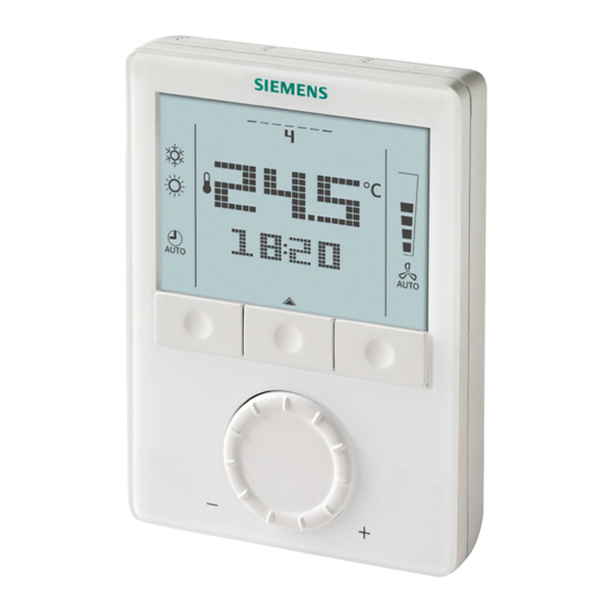
Heronhill - for all your Siemens requirements Operation See also Operating Instructions B3181 enclosed with the thermostat. Layout RDG100 RDG100T RDG110 RDG140 RDG160 1 Operating mode button / Esc 2 Button to enter the time and to set the timers... - Page 51 Confirmation of parameters Indicates that room temperature is displayed 51 / 60 Siemens RDG100, RDG100T, RDG110, RDG140, RDG160 Basic Documentation CE1P3181en Building Technologies Handling 28 May 2009 Tel: 01823 665660 www.heronhill.co.uk...
-
Page 52: Disposal
Heronhill - for all your Siemens requirements Disposal The device is classified as waste electronic equipment in terms of the European Directive 2002/96/EC (WEEE) and should not be disposed of as unsorted muni- cipal waste. The relevant national legal rules must be adhered to. -
Page 53: Engineering
Y12, Y22 Control output “Valve” AC 230 V (NC, for normally open valves) Y10, Y20 Control output for DC 0…10 V actuator 53 / 60 Siemens RDG100, RDG100T, RDG110, RDG140, RDG160 Basic Documentation CE1P3181en Building Technologies Engineering 28 May 2009 Tel: 01823 665660 www.heronhill.co.uk... -
Page 54: Connection Diagrams
Heronhill - for all your Siemens requirements Connection diagrams Note For details concerning connection of peripheral devices and setting of the DIP switches, please refer to the Mounting Instructions: – M3181.1 (RDG100, RDG100T) – M3181.2 (RDG110) – M3181.3 (RDG140, RDG160) RDG100…... - Page 55 1st or 2nd stage DC 0…10 V outputs Electrical heater DC 0…10 V controlled converter / current valve 55 / 60 Siemens RDG100, RDG100T, RDG110, RDG140, RDG160 Basic Documentation CE1P3181en Building Technologies Engineering 28 May 2009 Tel: 01823 665660 www.heronhill.co.uk...
-
Page 56: Mechanical Design
Heronhill - for all your Siemens requirements Mechanical design General The room thermostat consists of 2 sections: • Plastic housing which accommodates the electronics, the operating elements and the temperature sensor • Mounting plate with the screw terminals The housing engages in the mounting plate and is secured with 2 screws on the left side. -
Page 57: Technical Data
Ext. temperature sensor (P38=1) Input X2 Changeover sensor (P40=2) Operating mode switchover Input D1 (P42=3) 57 / 60 Siemens RDG100, RDG100T, RDG110, RDG140, RDG160 Basic Documentation CE1P3181en Building Technologies Technical data 28 May 2009 Tel: 01823 665660 www.heronhill.co.uk Fax: 01823 665807... - Page 58 Heronhill - for all your Siemens requirements Built-in room temperature sensor Measuring range 0…49 °C Accuracy at 25 °C < ± 0.5 K Temperature calibration range ± 3.0 K Settings and display resolution Setpoints 0.5 °C Current temperature value displayed 0.5 °C...
- Page 59 Operating mode button ..........11 ECM fan............. 7, 38 Operating mode input..........11 Electrical heater............. 23 Operating mode switchover ........40 59 / 60 Siemens RDG100, RDG100T, RDG110, RDG140, RDG160 Basic Documentation CE1P3181en Building Technologies Index 28 May 2009 Tel: 01823 665660 www.heronhill.co.uk...
- Page 60 Heronhill - for all your Siemens requirements Operating voltage ............ 7 Setpoint Comfort mode ......... 13 Overlapping of timer sequences......43 Setpoint Energy Saving mode....... 13 Setpoint limitation ..........12 Setpoint Protection mode ........13 Parameter setting ..........45 Setpoints and sequences ........13 Power failure............