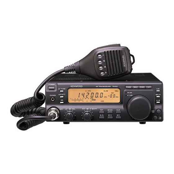
Kenwood TS-50S Service Manual
Hf transceiver
Hide thumbs
Also See for TS-50S:
- Service manual (130 pages) ,
- Instruction manual (62 pages) ,
- Service manual (77 pages)
Table of Contents
Advertisement
Quick Links
Download this manual
See also:
Instruction Manual
Advertisement
Table of Contents

Related Manuals for Kenwood TS-50S


Summary of Contents for Kenwood TS-50S
- Page 25 Downloaded by Amateur Radio Directory www.hamdirectory.info...