Siemens SINUMERIK 802D sl Programming And Operating Manual
Manual machine plus turning
Hide thumbs
Also See for SINUMERIK 802D sl:
- Function manual (462 pages) ,
- Programming and operating manual (364 pages) ,
- Instruction manual (262 pages)
Table of Contents
Advertisement
SINUMERIK SINUMERIK 802D sl Manual Machine Plus Turning
SINUMERIK
SINUMERIK 802D sl
Manual Machine Plus Turning
Programming and Operating Manual
Valid for
Controller
SINUMERIK 802D sl T/M 1.4 SP5
06/2009
6FC5398-6CP10-1BA0
Software version
Foreword
______________
Description
______________
Software interface
Turning On, Reference Point
______________
Approach
______________
Setting-up
______________
Manual machining
Machining the machining
______________
step program manually
______________
Messages
______________
Appendix
1
2
3
4
5
6
7
A
Advertisement
Table of Contents

Related Manuals for Siemens SINUMERIK 802D sl


Summary of Contents for Siemens SINUMERIK 802D sl
- Page 1 Foreword SINUMERIK SINUMERIK 802D sl Manual Machine Plus Turning ______________ Description ______________ Software interface SINUMERIK Turning On, Reference Point ______________ Approach SINUMERIK 802D sl ______________ Manual Machine Plus Turning Setting-up ______________ Manual machining Programming and Operating Manual Machining the machining...
- Page 2 Note the following: WARNING Siemens products may only be used for the applications described in the catalog and in the relevant technical documentation. If products and components from other manufacturers are used, these must be recommended or approved by Siemens. Proper transport, storage, installation, assembly, commissioning, operation and maintenance are required to ensure that the products operate safely and without any problems.
-
Page 3: Foreword
The Internet version of DOConCD (DOConWEB) is available at: http://www.automation.siemens.com/doconweb Information about training courses and FAQs (Frequently Asked Questions) can be found at the following website: http://www.siemens.com/motioncontrol under "Support". Target group This publication is intended for programmers, planning engineers, machine operators and system operators. - Page 4 Foreword Technical support If you have any technical questions, please contact our hotline: Europe / Africa Phone +49 180 5050 222 +49 180 5050 223 Internet http://www.siemens.com/automation/support-request America Phone +1 423 262 2522 +1 423 262 2200 E-Mail mailto:techsupport.sea@siemens.com Asia/Pacific...
- Page 5 The EC Declaration of Conformity for the EMC Directive can be found/obtained: ● on the internet: http://support.automation.siemens.com under the product/order No. 15263595 ● at the relevant regional office of the I DT MC Business Unit of Siemens AG. Manual Machine Plus Turning Programming and Operating Manual, 06/2009, 6FC5398-6CP10-1BA0...
-
Page 7: Table Of Contents
Table of contents Foreword ..............................3 Description..............................9 Control and display elements......................9 Error and status displays ......................10 Key definition of the full CNC keyboard (vertical format).............11 Key definition of the machine control panel .................13 Software interface............................ 15 Turning On, Reference Point Approach ....................17 Entry to the "Manual Machine Plus"... - Page 8 Table of contents 5.4.5 Manual grooving/parting......................65 5.4.5.1 Groove cycle - single........................65 5.4.5.2 Groove cycle - multiple........................ 68 5.4.5.3 Parting cycle - single ........................69 5.4.5.4 Multiple tapping ........................... 70 5.4.5.5 Extended grooving ........................71 5.4.5.6 Multiple extended grooving ......................75 5.4.6 Manual thread cutting........................
-
Page 9: Description
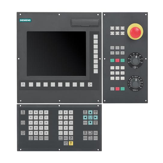
Description Control and display elements Operator control elements The defined functions are called up via the horizontal and vertical softkeys. For a description, please refer to this manual: Figure 1-1 CNC operator panel Manual Machine Plus Turning Programming and Operating Manual, 06/2009, 6FC5398-6CP10-1BA0... -
Page 10: Error And Status Displays
RDY (green) Ready for operation NC (yellow) Signoflife monitoring CF (yellow) Reading from/writing to CF card Reference You can find information on error description in SINUMERIK 802D sl, Diagnostics Manual Manual Machine Plus Turning Programming and Operating Manual, 06/2009, 6FC5398-6CP10-1BA0... -
Page 11: Key Definition Of The Full Cnc Keyboard (Vertical Format)
Description 1.3 Key definition of the full CNC keyboard (vertical format) Key definition of the full CNC keyboard (vertical format) Manual Machine Plus Turning Programming and Operating Manual, 06/2009, 6FC5398-6CP10-1BA0... - Page 12 Description 1.3 Key definition of the full CNC keyboard (vertical format) Hot keys In the part program editor and in the input fields of the HMI, the following functions can be carried out with certain key combinations on the full CNC keyboard: Keystroke combination Function <CTRL>...
-
Page 13: Key Definition Of The Machine Control Panel
Description 1.4 Key definition of the machine control panel Key definition of the machine control panel Manual Machine Plus Turning Programming and Operating Manual, 06/2009, 6FC5398-6CP10-1BA0... - Page 14 Description 1.4 Key definition of the machine control panel Note This documentation assumes an 802D standard machine control panel (MCP). Should you use a different MCP, the operation may be other than described herein. Manual Machine Plus Turning Programming and Operating Manual, 06/2009, 6FC5398-6CP10-1BA0...
-
Page 15: Software Interface
This Programming and Operating Manual focuses primarily on the software interface of the "Manual Machine Plus" system. For descriptions of the software interface for the SINUMERIK 802D sl control system, please refer to the SINUMERIK 802D sl Turning Programming and Operating Manual. -
Page 17: Turning On, Reference Point Approach
Turning On, Reference Point Approach Entry to the "Manual Machine Plus" operating area Operating sequences Note The operating area "Manual Machine Plus" runs only in Siemens mode, and not in ISO mode. Proceed as follows to open the "Manual Machine Plus" application: Note If the controller has already been preconfigured to "Manual Machine Plus"... - Page 18 Turning On, Reference Point Approach 3.1 Entry to the "Manual Machine Plus" operating area 3. You can access the "Manual Machine Plus" area by clicking on softkey "Manual": Note If you have not yet executed a reference point approach, the JOG REF operating mode will be reselected automatically when you press the "Manual"...
-
Page 19: Reference Point Approach
Turning On, Reference Point Approach 3.2 Reference point approach Reference point approach Functionality The axes have not yet approached their reference points (see screenshot below). Figure 3-3 Reference point approach Note The meanings of the symbols in the axis display are as follows: ->... - Page 20 Turning On, Reference Point Approach 3.2 Reference point approach Operating sequence 1. Select the <JOG> operating mode. Figure 3-4 Main screen for "Manual Machine Plus" 2. Select handwheel increment weighting using the <INCREMENT> key. Figure 3-5 Handwheel increment weighting 100 INC The current setting will appear on the top left of the screen (e.g.: 100 INC).
- Page 21 Turning On, Reference Point Approach 3.2 Reference point approach 3. Then use the handwheel to move the axes to a position from which they can approach the reference point in a positive direction. CAUTION In this operating state, the axes can be moved only by means of the handwheel. Traversing the axes using the axis traversing switch is inhibited.
-
Page 23: Setting-Up
You can access the tool list by pressing the operating area key <OFFSET/PARAM> and softkey "Tool list". Literature Further methods of handling tools and tool offsets are described in the "SINUMERIK 802D sl Turning Programming and Operating Manual". DANGER Notice: An uncalibrated or incorrectly calibrated tool can lead to dimensional errors or to incorrect cutting values. - Page 24 Setting-up 4.1 Measuring tools Operating sequences Proceed as follows to measure the tool for the X axis of the loaded turning tool. 1. Press the "Meas. tool" softkey. The following screen appears: Figure 4-1 Measure a turning tool 2. Press the "X" softkey. The screen for measuring the X axis (L1) appears.
- Page 25 Setting-up 4.1 Measuring tools 9. Press the "Set length" softkey. The modified tool offset for the selected tool is applied in the X axis. Provided that the "scratch position" in the X axis has not been moved, the measured diameter is now displayed as the actual position in the position display of the tool measurement screen.
-
Page 26: Limit Stops
Setting-up 4.2 Limit stops Limit stops Functionality Limit stops are used to stop the axes in a specific position. If an axis stops in the limit stop position, it cannot be moved again until the triggering limit stop is reset. By setting the limit stops, in the "Manual Machine Plus"... - Page 27 Setting-up 4.2 Limit stops Parameter Parameter Description The limit stop is activated. The limit stop is deactivated. Negative absolute position of the limit stop of the X axis. The axis stops automatically if: The limit stop is active. • The specified axis traverses in the negative direction and reaches the absolute limit stop position. •...
- Page 28 Setting-up 4.2 Limit stops Operating sequences You can use the following methods to enter a limit stop position: ● Direct position entry: – Select the input field of the relevant limit stop with the <Cursor keys>. – Now use the <Numeric keys> to enter the absolute position you require. –...
-
Page 29: Turning Against A Stop
Setting-up 4.2 Limit stops 4.2.2 Turning against a stop Example: The following example explains the operating principle of limit stops using the axis direction keys. You can also use the handwheel to perform the machining operation. Task The following shoulder with a finishing allowance of 0.2 mm must be turned: ●... - Page 30 Setting-up 4.2 Limit stops 12. Using the handwheel, infeed to the next depth of cut in the X direction. 13. Start machining in the Z axis in the negative direction using the axis direction switch. Repeat the procedure until the depth of rough cut is reached. The message "Limit stop -X reached"...
-
Page 31: Setting The Workpiece Zero
Setting-up 4.3 Setting the workpiece zero Setting the workpiece zero Functionality The “Set the workpiece zero" function can be used to specify the reference point for machining the workpiece. Typical application/procedure: 1. Parameterize all the machining steps (cycles) for the workpiece in relation to a “virtual zero point”... - Page 32 Setting-up 4.3 Setting the workpiece zero Operating sequences Press the "Set WO" softkey in the main screen for "Manual Machine Plus". Figure 4-5 Set workpiece zero point This screen displays the currently programmed Z value of the basic work offset. The setting options in this screen are selected with softkeys.
-
Page 33: Manual Machining
Manual machining Fundamentals of manual machining Note Please refer to the SINUMERIK 802D sl operating instructions for a description of the relevant commissioning requirements. Functionality You can perform the following machining operations manually: ● Axis-parallel traversal ● Taper turning ● Radius turning ●... -
Page 34: Display And Operator Control Optios In The Main Screen For "Manual Machine Plus
If you have not yet executed a reference point approach, you will be in the operating mode Reference point approach after start-up. You can reference the axes in the Siemens standard user interface as well as in the operating area "Manual Machine Plus". - Page 35 Manual machining 5.2 Display and operator control optios in the main screen for "Manual Machine Plus" Controlling the axes and spindle In manual machining mode, the axes and spindle can be controlled by the following methods: ● The compound slide rest is controlled by: –...
- Page 36 Manual machining 5.2 Display and operator control optios in the main screen for "Manual Machine Plus" Displayed values Meaning Feed stop as a result of: • – Feedrate override at position 0%. – An alarm is active which prevents the axes from moving. Spindle status •...
- Page 37 Manual machining 5.2 Display and operator control optios in the main screen for "Manual Machine Plus" DANGER Notice: When constant cutting rate (G96) is selected, the maximum permissible spindle speed, corresponding to the fitted tool chucking device must be entered in the input field MR (spindle speed limitation)! Failure to pay sufficient attention to this point can lead to serious damage as a result of the chucking device speed being exceeded.
-
Page 38: Toggling The Display
Manual machining 5.2 Display and operator control optios in the main screen for "Manual Machine Plus" 5.2.1 Toggling the display Functionality In the position display screen you can edit the displayed values using the vertical softkeys. Figure 5-4 Main screen for "Manual Machine Plus" Softkeys Change the display to "relative position display"... -
Page 39: Machining With The Handwheels
Manual machining 5.2 Display and operator control optios in the main screen for "Manual Machine Plus" 5.2.2 Machining with the handwheels Functionality The handwheels for the X and Z axis are not mechanically connected to the feed screws. Electronic pulse generators mounted on the handwheels generate the information needed by the controller to execute the required traversing movement. -
Page 40: Spindle Advance/Reverse
Manual machining 5.2 Display and operator control optios in the main screen for "Manual Machine Plus" The axis feedrate is also influenced by the feedrate override weighting setting and, depending on the option selected in the machining technology screen (revolutional feed/cutting speed), by the spindle override weighting. -
Page 41: Tool Change
Manual machining 5.2 Display and operator control optios in the main screen for "Manual Machine Plus" 5.2.6 Tool change Functionality A basic differentiation must be made between a manual and an automatic tool-changer system. For an automatic system, the tool change is controlled by the PLC user program. The currently loaded tool is displayed in the "Manual Machine Plus"... - Page 42 Manual machining 5.2 Display and operator control optios in the main screen for "Manual Machine Plus" 4. Press the <NC-Start> key. The tool change is changed. Please note the following for a manual tool change: ● The real tool change on the machine (tool relocation) is finished. ●...
-
Page 43: Changing The Feedrate/Spindle Value
Manual machining 5.2 Display and operator control optios in the main screen for "Manual Machine Plus" 5.2.7 Changing the feedrate/spindle value Changing the operating sequence, feed rate "F"/ spindle value "S" Follow the sequence of operations below to enter the required feedrate or spindle value: 1. -
Page 44: Changing The Feedrate/Spindle Type
Manual machining 5.2 Display and operator control optios in the main screen for "Manual Machine Plus" 5.2.8 Changing the feedrate/spindle type Changing the operating sequences feedrate type "F" By pressing the <Cursor keys>, you go to the display field which contains the currently programmed feedrate type (on dark background). - Page 45 Manual machining 5.2 Display and operator control optios in the main screen for "Manual Machine Plus" By pressing the toggle key <SELECT>, you can choose one of the following spindle types: ● Constant spindle speed (rpm) This value defines the programmed spindle speed for machining with "Spindle speed + Time feed"...
-
Page 46: Change The Speed Limitation For Constant Cutting Rate
Manual machining 5.2 Display and operator control optios in the main screen for "Manual Machine Plus" 5.2.9 Change the speed limitation for constant cutting rate Change the speed limitation operating sequences When a constant cutting rate (G96) is programmed, the maximum permissible spindle speed, corresponding to the fitted tool chucking device must be entered in the input field "MR"... -
Page 47: Manual Machining With Machining Types
Manual machining 5.3 Manual machining with machining types Manual machining with machining types 5.3.1 Axis-parallel traversal Functionality The axis-parallel traversal is used for the simple cutting on the workpiece or for positioning the axes. If you move the axis direction switch, the control then moves the X and Z axes accordingly. Operating sequences 1. -
Page 48: Manual Taper Turning
Manual machining 5.3 Manual machining with machining types 5.3.2 Manual taper turning Functionality The "Manual taper turning" function is intended for the simple production of tapered workpieces. For the machining type "Taper turning" you need to enter an angle (taper angle α). The angle input rotates the controller’s internal coordinate system according to the angle value. -
Page 49: Manual Radius Turning
Manual machining 5.3 Manual machining with machining types 3. The input field for the taper angle "α" is immediately displayed on a dark background when the machining mode is selected. You must enter the angle using the <Numeric keys>. A positive angle value rotates the coordinate system in traverse direction X+. A negative angle value rotates the coordinate system in traverse direction X-. - Page 50 Manual machining 5.3 Manual machining with machining types Operating sequences 1. You can access the "Manual radius turning" function in the main screen for "Manual Machine Plus". 2. Press the "Machining mode" softkey until "Taper turning" is displayed. Figure 5-13 Radius turning The "Radius turning"...
- Page 51 Manual machining 5.3 Manual machining with machining types DANGER Notice: Omitting or using the wrong sign for the input values or entering the wrong arc direction can lead to a collision and may destroy the tool or the workpiece. Note Any limit stops that are activated should be disabled before starting radius turning or set to a value outside the traversing range needed for radius turning.
-
Page 52: Radius Turning Type A
Manual machining 5.3 Manual machining with machining types 5.3.3.1 Radius turning type A For the radius turning type A, the radius to be machined is specified by the end point, the radius and the machining direction. Figure 5-15 Radius turning type A Parameter Parameter Description... -
Page 53: Radius Turning Type C
Manual machining 5.3 Manual machining with machining types Parameter Parameter Description This input value describes the position of the circle center in the X axis. The input value is evaluated as absolute position (in the diameter). This input value describes the position of the circle center in the Z axis. The input value is evaluated as absolute position. -
Page 54: Manual Machining Using Cycles (Functions)
Manual machining 5.4 Manual machining using cycles (functions) Manual machining using cycles (functions) 5.4.1 Principle operating sequence Functionality You can perform the following functions manually: ● Drilling centric ● Tapping ● Groove cycles/Parting ● Thread cutting ● Rough turning of contours When manually machining these functions, the operating sequence is essentially executed in the same way. - Page 55 Manual machining 5.4 Manual machining using cycles (functions) Operating sequences 1. Select the function (e.g. "Drilling " > "Tapping") in the main screen of the "Manual Machine Plus". 2. Parameterizing the function. Figure 5-18 Example of input fields Note A detailed parameter description of each function can be found in the relevant sections. The following softkeys will support you with the parameterization and execution of functions: The actual position value of the relevant axis is transferred to the parameter input fields...
- Page 56 Manual machining 5.4 Manual machining using cycles (functions) This softkey takes you back to the main screen. If you have edited any values, the following prompt window appears: Figure 5-19 Cycles prompt text Your inputs are accepted when you press the "OK" softkey. Your inputs are discarded when you press the "Abort"...
- Page 57 Manual machining 5.4 Manual machining using cycles (functions) Note Press the <NC-Stop> key if you want to interrupt the machining operation. The selected direction of the spindle rotation continues to be activated. By pressing the key <NC stop>, the operating mode JOG is automatically changed, i.e. you can traverse the axes manually.
-
Page 58: General Parameters
Manual machining 5.4 Manual machining using cycles (functions) 5.4.2 General parameters General parameters When parameterizing the particular functions, among others, the following general parameters are available: Parameter Description Function name Number of the selected function Tool Tool number Compensation Tool offset number Direction of spindle rotation Toggle field for spindle direction of rotation (clockwise/counterclockwise) Feed value... - Page 59 Manual machining 5.4 Manual machining using cycles (functions) Optional parameter, gear stage preselection In the input fields for the relevant manual machining, e.g. thread tapping, it is possible to pre- select the gear stage (see screenshot below). Figure 5-21 Gear stage preselection If a gear unit is installed on the machine, you can select the gear stage using the <SELECT>...
-
Page 60: Manual Drilling Centered
Manual machining 5.4 Manual machining using cycles (functions) 5.4.3 Manual drilling centered Functionality The "Manual drilling centered" function is designed to produce deep-hole drill holes in the turning center. Before you start the cycle, you must position the tool in such a way that it can approach the programmed Z initial position without risk of collision. - Page 61 Manual machining 5.4 Manual machining using cycles (functions) You can access the "Manual center drilling" function by pressing the softkey "Center drilling" in the drilling cycle overview. Alternatively, you can select "Center drilling" with <Cursor keys> and activate with the input key.
-
Page 62: Manual Thread Tapping
Manual machining 5.4 Manual machining using cycles (functions) Drilling The machining sequence is as follows: 1. Starting from the current axis position, the tool is traversed to the cycle start point in the longitudinal axis. This is calculated internally from the value for the "Reference z0" parameter (taking into account the clearance distance). - Page 63 Manual machining 5.4 Manual machining using cycles (functions) DANGER Notice: If "Time feed" is selected in the “Machining technology data” screen, in order for the pitch to be calculated correctly, the spindle override weighting must be set to "100%". Otherwise, the tapping tool or workpiece may be damaged!! ->Prior to NC start, check that the spindle override weighting is set to 100%! Operating sequences You can access the drilling cycle overview by pressing the softkey "Drilling"...
- Page 64 Manual machining 5.4 Manual machining using cycles (functions) You can access the "Manual tapping" function by pressing the softkey "Tapping" in the drilling cycle overview. Alternatively, you can select "Tapping" with <Cursor keys> and activate with the input key. Figure 5-25 Tapping Parameter Parameter...
-
Page 65: Manual Grooving/Parting
Manual machining 5.4 Manual machining using cycles (functions) See also Principle operating sequence (Page 54) General parameters (Page 58) 5.4.5 Manual grooving/parting Functionality The "Manual grooving" function is suitable for producing grooves on the peripheral surface and face end and for tapping turned parts. Groove cycles can be used to produce filleted corners or beveled edges on surfaces. - Page 66 Manual machining 5.4 Manual machining using cycles (functions) Figure 5-27 Outer groove Figure 5-28 Inner groove Parameter Parameter Description Reference Starting position for the groove. The edge of the groove facing the chuck is always specified here. The value to be entered is the absolute position in the longitudinal axis (Z axis).
- Page 67 Manual machining 5.4 Manual machining using cycles (functions) Parameter Description Groove depth This value is the groove depth which together with the value for "Diameter d" specifies the absolute position of the base of the groove. Chamfer/radius Depending on the option selected, this value forms either an input radius (display "Radius RND") or an input chamfer (display "Chamfer CHF") of less than 45 on both sides of the groove.
-
Page 68: Groove Cycle - Multiple
Manual machining 5.4 Manual machining using cycles (functions) 5.4.5.2 Groove cycle - multiple Functionality Note The "Multiple groove" function supplements the "Single groove" option. This function can be used only if all the parameters for the "Groove cycle - single" function have been assigned! As soon as you position the cursor in any of the input fields in the multiple grooves area of the screen, the display changes from single groove to multiple grooves: Figure 5-29... -
Page 69: Parting Cycle - Single
Manual machining 5.4 Manual machining using cycles (functions) Multiple grooves The machining sequence is as follows: 1. Starting from the current axis position, the first groove is produced as described under "Groove cycle - single". 2. The starting point for the next groove is then approached in the longitudinal axis (X axis), taking into account the clearance distance. -
Page 70: Multiple Tapping
Manual machining 5.4 Manual machining using cycles (functions) Parting The machining sequence is as follows: 1. Starting from the current axis position, the first calculated parting position is approached (diagonally) in both axes, taking into account the clearance distance. 2. Execute the depth infeeds as a roughing motion in the transverse axis (X axis): each infeed depth is calculated internally so that firstly the setting "m1"... -
Page 71: Extended Grooving
Manual machining 5.4 Manual machining using cycles (functions) Multiple tapping DANGER Notice: When multiple parting is selected, make sure that there is sufficient clearance from the spindle as measured from starting position "Reference z0" to allow all parameterized parting operations to be performed. There is otherwise a risk of collision between the tool and the chuck! ->... - Page 72 Manual machining 5.4 Manual machining using cycles (functions) You can access the "Extended grooving" function by pressing the softkey "Extended groove" in the grooving cycle overview. Alternatively, you can select "Extended groove" with <Cursor keys> and activate with the input key. Figure 5-31 Extended external groove Figure 5-32...
- Page 73 Manual machining 5.4 Manual machining using cycles (functions) Figure 5-33 Face groove Parameter Parameter Description Reference Starting position for the groove. The edge of the groove facing the chuck is always specified here. The value to be entered is the absolute position in the longitudinal axis (Z axis).
- Page 74 Manual machining 5.4 Manual machining using cycles (functions) Parameter Description Finishing allowance Finishing allowance perpendicular to the contour. External In this toggle field you can select the type of groove machining required whereby the groove/internal respective selection is displayed in a diagram on the screen. groove/planar to chuck/planar from chuck...
-
Page 75: Multiple Extended Grooving
Manual machining 5.4 Manual machining using cycles (functions) 5.4.5.6 Multiple extended grooving Functionality Note The "Multiple extended grooving" function supplements the "Extended grooving" option. This function can be used only if all the parameters for the "Extended grooving" function have been assigned! As soon as you position the cursor in any of the input fields in the multiple grooves area of the screen, the display changes from single groove to multiple grooves:... -
Page 76: Manual Thread Cutting
Manual machining 5.4 Manual machining using cycles (functions) Parameter Parameter Description Distance Groove offset: This input value determines the offset between several identical grooves during production. Number Number of grooves to be produced. Entering "0" or "1" here has the same effect: A single groove is produced. -
Page 77: Thread Cutting
Manual machining 5.4 Manual machining using cycles (functions) 5.4.6.1 Thread cutting Operating sequences You can access the "Manual thread cutting" function by pressing the softkey "Thread" in the main screen for "Manual Machine Plus". Figure 5-36 Longitudinal external thread Figure 5-37 Longitudinal internal thread Manual Machine Plus Turning Programming and Operating Manual, 06/2009, 6FC5398-6CP10-1BA0... - Page 78 Manual machining 5.4 Manual machining using cycles (functions) Figure 5-38 Face thread Figure 5-39 Taper external thread Figure 5-40 Taper internal thread Manual Machine Plus Turning Programming and Operating Manual, 06/2009, 6FC5398-6CP10-1BA0...
- Page 79 Manual machining 5.4 Manual machining using cycles (functions) Parameter Parameter Description Reference Start position for the thread in the longitudinal axis (absolute position of the Z axis). Thread length Enter the length of the thread to be created, taking the start position for the thread ("Reference z0") as the starting point.
- Page 80 Manual machining 5.4 Manual machining using cycles (functions) Parameter Description Linear infeed/ This function key is used to switch between "linear infeed" and "degressive infeed". "Linear Degressive infeed infeed" means that roughing always takes place at a constant depth of cut, and the internal infeed calculation is designed so that the value for the "max.
-
Page 81: Thread Recutting
Manual machining 5.4 Manual machining using cycles (functions) 5.4.6.2 Thread recutting Functionality The "Thread recutting" function is a subfunction of "Manual thread cutting". It can be used to recut a thread or to continue machining the thread on a workpiece that has been unclamped in between. - Page 82 Manual machining 5.4 Manual machining using cycles (functions) Execute thread recut The following requirements must be fulfilled before you can recut a thread: ● Appropriate values must already have been entered in the "Thread Cutting" screen form at this point. ●...
-
Page 83: Thread Shaving After Thread Cutting
Manual machining 5.4 Manual machining using cycles (functions) 5.4.6.3 Thread shaving after thread cutting Functionality At the end of each thread cutting operation, you can choose to continue machining the thread, i.e., to perform shaving. Thread shaving can be performed either with or without an additional infeed, in which case it is merely a "smoothing cut". -
Page 84: Roughing Cycles
Manual machining 5.4 Manual machining using cycles (functions) 5.4.7 Roughing cycles Functionality The roughing cycles (integrated in the control) are the easiest way of producing common paraxial cutting contours. They are defined by setting particular input parameters in the appropriate screen forms. The contour can be machined using the following position of the contour: ●... -
Page 85: Roughing Cycle A
Manual machining 5.4 Manual machining using cycles (functions) 5.4.7.1 Roughing cycle A Functionality The function "Roughing A" is used to produce a simple stepped contour (step), with the option of working the transitions to adjacent faces as a radius or chamfer. Operating sequences You can access the turning cycle overview by pressing the softkey "Turning"... - Page 86 Manual machining 5.4 Manual machining using cycles (functions) Parameter Description Chamfer/radius Depending on the option selected, this value forms either a transition radius (display "RND") or a transition chamfer (display "Chamfer CHR" or "Chamfer CHF") of less than 45 between the end face and the inside diameter of the "step". You can toggle between RND / CHR / CHF using the toggle key.
- Page 87 Manual machining 5.4 Manual machining using cycles (functions) Figure 5-46 Roughing cycle A, position "Inside right" Figure 5-47 Roughing cycle A, position "Outside left" See also General parameters (Page 58) Principle operating sequence (Page 54) Manual Machine Plus Turning Programming and Operating Manual, 06/2009, 6FC5398-6CP10-1BA0...
-
Page 88: Roughing Cycle B
Manual machining 5.4 Manual machining using cycles (functions) 5.4.7.2 Roughing cycle B Functionality The function "Roughing B" is used to produce a simple cutting contour, with an additional interpolation point allowing beveled or tapered contours. Transitions to adjacent faces can again be worked as a radius or chamfer. - Page 89 Manual machining 5.4 Manual machining using cycles (functions) Input fields The input fields in the "Roughing B" screen form have the following meanings: Parameter Description Length Enter the length of the "step" to be produced, taking the contour start position ("Reference z0") in the axial axis (Z axis) as the starting point.
- Page 90 Manual machining 5.4 Manual machining using cycles (functions) The following possibilities exist for the position of the geometry: Figure 5-49 Roughing cycle B, position "Inside right" Figure 5-50 Roughing cycle B, position "Outside left" See also General parameters (Page 58) Principle operating sequence (Page 54) Manual Machine Plus Turning Programming and Operating Manual, 06/2009, 6FC5398-6CP10-1BA0...
-
Page 91: Roughing Cycle C
Manual machining 5.4 Manual machining using cycles (functions) 5.4.7.3 Roughing cycle C Functionality The function "Roughing C" is used to produce a special cutting contour, with a filleted transition between the inside and outside diameter of the contour. Other chamfers or radii cannot be included. - Page 92 Manual machining 5.4 Manual machining using cycles (functions) Input fields The input fields in the "Roughing C" screen form have the following meanings: Parameter Description Length Enter the end point of the contour in the axial axis here, taking the contour start position ("Reference z0") in the axial axis (Z axis) as the starting point.
- Page 93 Manual machining 5.4 Manual machining using cycles (functions) Figure 5-53 Roughing cycle C, position "Outside left" See also General parameters (Page 58) Principle operating sequence (Page 54) Manual Machine Plus Turning Programming and Operating Manual, 06/2009, 6FC5398-6CP10-1BA0...
-
Page 94: Roughing Cycle D
Manual machining 5.4 Manual machining using cycles (functions) 5.4.7.4 Roughing cycle D Functionality The function "Roughing D" allows a single radius contour to be machined, supported by cycles. Operating sequences You can access the turning cycle overview by pressing the softkey "Turning" in the basic screen for "Manual Machine Plus". - Page 95 Manual machining 5.4 Manual machining using cycles (functions) Input fields The input fields in the "Roughing D" screen form have the following meanings: Parameter Description Length Enter the end point of the contour in the axial axis here, taking the contour start position ("Reference z0") in the axial axis (Z axis) as the starting point.
- Page 96 Manual machining 5.4 Manual machining using cycles (functions) Figure 5-56 Roughing cycle D, position "Outside left" See also General parameters (Page 58) Principle operating sequence (Page 54) Manual Machine Plus Turning Programming and Operating Manual, 06/2009, 6FC5398-6CP10-1BA0...
-
Page 97: Roughing Cycle E
Manual machining 5.4 Manual machining using cycles (functions) 5.4.7.5 Roughing cycle E Functionality The function "Roughing E" allows a single taper contour to be machined, supported by cycles. Operating sequences You can access the turning cycle overview by pressing the softkey "Turning" in the basic screen for "Manual Machine Plus". - Page 98 Manual machining 5.4 Manual machining using cycles (functions) Parameter Description Angle α Angle of the taper to be machined. The reference point is either d1 or d2 depending on which dimensioning type is selected. Max. infeed depth Enter the maximum infeed depth for roughing. The internal infeed calculation ensures that the infeed is as uniform as possible throughout the roughing operation.
-
Page 99: Roughing Cycle F
Manual machining 5.4 Manual machining using cycles (functions) 5.4.7.6 Roughing cycle F Functionality The function "Roughing F" allows cycle-supported production of an end face (cutting direction "Planar") or of a peripheral surface (cutting direction "Longitudinal"). Operating sequences You can access the turning cycle overview by pressing the softkey "Turning" in the basic screen for "Manual Machine Plus". - Page 100 Manual machining 5.4 Manual machining using cycles (functions) Input fields The input fields in the "Roughing F" screen form have the following meanings: Parameter Description Length Enter here the length of the end face to be cut, taking the contour start position ("Reference z0") in the longitudinal axis (Z axis) as the starting point.
-
Page 101: Roughing Cycle, Free Contour
Manual machining 5.4 Manual machining using cycles (functions) 5.4.7.7 Roughing cycle, free contour: Functionality The cycle "Free contour" is used for the input and for the processing of an arbitrary contour path. Operating sequences You can access the turning cycle overview by pressing the softkey "Turning" in the basic screen for "Manual Machine Plus". - Page 102 Manual machining 5.4 Manual machining using cycles (functions) Softkeys The "Cycle overview" function lists all free contours contained in the machining step program. Figure 5-63 Free contour - overview To select, place the cursor on the appropriate line and press the "OK" softkey. It is also possible to assign a contour of an external contour subroutine to the cycle.
- Page 103 Manual machining 5.4 Manual machining using cycles (functions) The function branches to the contour input. Note Only contours listed in the cycle overview can be machined. External contours cannot be machined. Figure 5-65 Machining window for free contours First, define the contour starting point. Manual Machine Plus Turning Programming and Operating Manual, 06/2009, 6FC5398-6CP10-1BA0...
- Page 104 Manual machining 5.4 Manual machining using cycles (functions) References The function "Machine contour" is described in detail in the SINUMERIK 802D sl Turning Programming and Operating Manual in the chapter "Part programming; Free contour programming, ... Define a start point".
-
Page 105: Execute A Roughing Cycle
Manual machining 5.4 Manual machining using cycles (functions) 5.4.7.8 Execute a roughing cycle Rough cutting Starting from the current axis position, the rough cutting sequence is as follows: 1. Diagonal approach to the start position calculated in the cycle in both axes. The safety clearance and finishing allowance are taken into account. -
Page 107: Machining The Machining Step Program Manually
Machining the machining step program manually Functionality The "machining step program" function can be used to define a list containing an optional sequence of machining cycles. This list can then be automatically machined step by step. The controller can store a maximum of 390 steps. Operating sequences Figure 6-1 Entry into the machining step program... - Page 108 Machining the machining step program manually 5.4 Manual machining using cycles (functions) Figure 6-2 Machining step program Screen handling functions "Cursor up / down" With the cursor up/cursor down keys, you can move selected machining steps up and down within the list.
- Page 109 Machining the machining step program manually 5.4 Manual machining using cycles (functions) Displays a dialog used to open an existing machining step program or create a new machining step program. If the file is not located in drive N (NC storage), ensure that the external medium is not removed during the machining.
- Page 110 Machining the machining step program manually 5.4 Manual machining using cycles (functions) Inserting a traversing block in the program. Inserting a roughing cycle in the program. Change into the dialog box for roughing cycles (Page 84). Inserting a drilling cycle in the program. Change into the dialog box (Page 60) for the drilling cycles (Page 62).
-
Page 111: Tool Change In The Machining Step Program
Machining the machining step program manually 6.1 Tool change in the machining step program Tool change in the machining step program Functionality You add a tool change step to the machining step program. If the value of the display machine data 361 (USER_MEAS_TOOL_CHANGE) is 1, the tool number can be specified manually. - Page 112 Machining the machining step program manually 6.1 Tool change in the machining step program 3. To select the tool, enter the tool number and the cutting edge number in the input fields "T" and "D", respectively. - OR - Use the <Tab key> to change to the list and position the cursor on the appropriate tool and press the <INPUT>...
- Page 113 Machining the machining step program manually 6.1 Tool change in the machining step program 7. If you press "Cancel", the tool change only takes place in this step, or if you press "OK", the tool is also changed in all subsequent program steps. Figure 6-8 Tool change in the machining step program, confirmation 8.
-
Page 114: Teach In
Machining the machining step program manually 6.2 Teach In Teach In Functionality Using this function, an approached axis position can be directly entered into a specific traversing block. Operating sequences 1. You can reach the "Teach In" function in the machining step program by pressing the "Teach In"... - Page 115 Machining the machining step program manually 6.2 Teach In 2. Traverse to a position that is to be taught-in and press "Save block". Figure 6-12 "Save block" menu 3. You can save the position with path feed. 4. You can save the position with rapid traverse. After the control acknowledged the action with a screen message (e.g.: "The block was inserted as N20"), a new position could be traversed to and this in turn taught-in using "Save block".
- Page 116 Machining the machining step program manually 6.2 Teach In 5. Exit the "Teach In" mode using the function "Finish Teach In". The menu returns to the machining step program. The cursor is at the last block that was entered (refer to the following screen shot). Figure 6-14 Machining step program "Teach In"...
-
Page 117: Simulate Machining
Machining the machining step program manually 6.3 Simulate machining Simulate machining Function You can use this function to graphically display the execution of the program on the screen, in order to easily control the programming result without moving the machine axes. Operating sequences The start screen is opened. - Page 118 Machining the machining step program manually 6.3 Simulate machining Contour simulation Execution of the part program is simulated with this function on the HMI. Figure 6-16 Contour simulation The selected part program is started for the contour simulation. Simulation of individual cycles Note If the simulation is used to test a single cycle, the display area is divided into the traversing movements and technology data columns.
- Page 119 Simulation of a single cycle - contour simulation References A description of further operating options for a simulation can be found in the "Programming and Operating Manual SINUMERIK 802D sl Turning". Manual Machine Plus Turning Programming and Operating Manual, 06/2009, 6FC5398-6CP10-1BA0...
-
Page 120: Executing The Machining Step Program
Machining the machining step program manually 6.4 Executing the machining step program Executing the machining step program Functionality Figure 6-19 Machining step program In the "Machining step program" function, you can toggle between the horizontal softkey functions "Execute" and "Exec. here" using the <ETC> key. The two functions change from the "Machining step program"... - Page 121 Machining the machining step program manually 6.4 Executing the machining step program Operating sequences, executing the machining step program The current machining status is displayed in the center of the execute screen (see the screen "Executing the machining step program"). This status could be one of the following: ●...
-
Page 123: Messages
Messages Messages Functionality The meanings of the messages listed below differ from those given in the general "SINUMERIK Diagnostics Guide": 10631 +X limit stop reached 10631 +X limit stop reached 10631 -Z limit stop reached 10631 +Z limit stop reached PLC alarm messages are specially configured for the "Manual Machine Plus"... - Page 124 Messages 7.1 Messages 700020 LUBRICANT MOTOR OVERHEATING 700021 LUBRICANT TOO LOW 700022 TURRET HEAD MOTOR OVERHEATING 700023 PROGR.TOOL NO. > MAX.TOOL NO. ON TURRET HEAD 700024 802D MACHINE CONTROL PANEL DEFECT 700025 BRAKE IS RELEASED FOR MOTOR OPTIMIZATION 700026 NO CHECKBACK FROM TURRET HEAD 700027 700028 700029...
-
Page 125: Appendix
This document will be continuously improved with regard to its quality and ease of use. Please help us with this task by sending your comments and suggestions for improvement via e-mail or fax to: E-mail: mailto:docu.motioncontrol@siemens.com Fax: +49 9131 - 98 2176 Please use the fax form on the back of this page. - Page 126 Appendix A.1 Feedback on the documentation Manual Machine Plus Turning Programming and Operating Manual, 06/2009, 6FC5398-6CP10-1BA0...
-
Page 127: Overview Of Documentation
Appendix A.2 Overview of documentation Overview of documentation Manual Machine Plus Turning Programming and Operating Manual, 06/2009, 6FC5398-6CP10-1BA0... -
Page 129: Index
Index Axis direction switch, 39 LED displays on the CNC operator panel (PCU), 10 Axis-parallel traversal, 47 Limit stop position, 26 Limit stops, 26, 29 Contour list, 102 End face, 99 Machine contour, 104 Peripheral surface, 99 Machining step program, 107 cutting rate, 45 Simulation, 117 Teach In, 114... - Page 130 Index S value/S type, 35 Spindle, 40 Spindle speed, 40, 45 Spindle speed limitation, 46 Spindle type, 44 Spindle value, 43 Status displays, 10 T value, 35 Taper turning, 48 Tapping, 62 Thread cutting, 76 Thread recutting, 81 Time feed, 44 Tool change, 42 Tool measurement, 23 Travel direction, 35...