Table of Contents
Advertisement
Quick Links
is a registered trademark owned by Victor Company of Japan, Limited.
is a registered trademark in Japan, the U.S.A., the U.K. and many other countries.
2005 Victor Company of Japan, Limited
HD VIDEO CASSETTE RECORDER
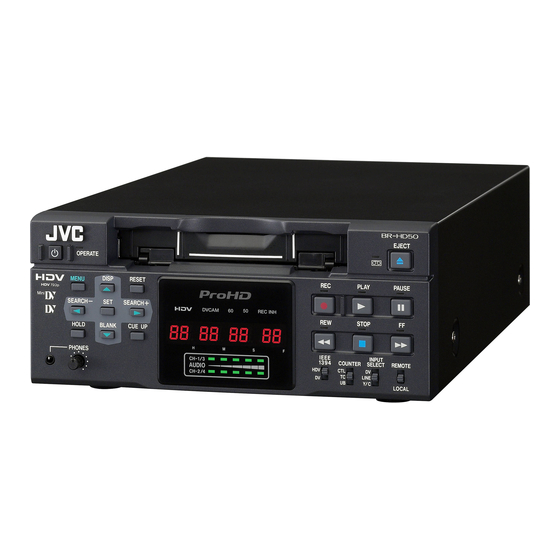
BR-HD50
This instruction manual is made from 100%
recycled paper.
Thank you for purchasing this JVC product.
Before operating this unit, please read the
instructions carefully to unsure the best possi-
ble performance.
Printed in Japan
LLT0088-001A
E
INSTRUCTION MANUAL
For Customer Use:
Enter below the Serial No. which is
located on the rear of cabinet. Retain
this information for future reference.
Model No.
BR-HD50U
Serial No.
LLT0088-001A
Advertisement
Table of Contents

Related Manuals for JVC BR-HD50


Summary of Contents for JVC BR-HD50
- Page 1 HD VIDEO CASSETTE RECORDER BR-HD50 This instruction manual is made from 100% recycled paper. Thank you for purchasing this JVC product. Before operating this unit, please read the instructions carefully to unsure the best possi- ble performance. Printed in Japan...
- Page 2 However, there is no guarantee that interfer- WARNING: ence will not occur in a particular installation. The battery used in the BR-HD50 must be replaced by a JVC If this equipment does cause harmful interference to radio or authorized service dealer only.
- Page 3 Union. national legislation. (Business users) If you wish to dispose of this product, please visit our web page www.jvc-europe.com to obtain information about the take-back of the product. [Other Countries outside the European Union] If you wish to dispose of this product, please do so in accordance with applicable national legislation or other rules in your country for the treatment of old electrical and electronic equipment.
-
Page 4: Table Of Contents
Thank you for purchasing our HD Video Equipped with HDMI terminal Outputs digital video and digital audio. Cassette Recorder BR-HD50 View HD video on monitors with an HDMI ter- minal. This instruction manual was made for the BR- HD50U and the BR-HD50E. -
Page 5: Introduction
DV and mini DV cassette tapes (for SP mode DV cassettes have a safety slide at the back to only). prevent accidental erasure. Use the following JVC cassettes with the B or • To prevent accidental erasure of important A the logo. Standard DV cas- Mini DV cassettes •... -
Page 6: Hdv And Dv Format
INTRODUCTION HDV and DV format This unit records in HDV or DV format. DV format is a standard for recording SD (Standard-Definition) video onto DV cassettes or mini DV cas- settes. HDV format is a standard for recording HD (High-Definition) video onto DV cassettes or mini DV cas- settes. -
Page 7: Regular Maintenance
: You can check the drum usage time with the hour meter display. For details, refer to page 83, “Checking the hour meter”. Maintenance consultation : For details on the maintenance plan and fee, consult with your JVC- authorized service agent. Head cleaning •... -
Page 8: Names And Functions Of Parts Front Panel
Even after the power is turned off with this but- ton, BR-HD50 is live with a small amount of electricity. Therefore, if BR-HD50 is not to be used for a long period of time, please remove the AC adapter to save energy. - Page 9 NAMES AND FUNCTIONS OF PARTS Front panel (continued) 5[REMOTE/LOCAL] switch 6[INPUT SELECT] switch This switch is used to select how BR-HD50 is This switch is used to select input signals. to be operated. HDV/DV : Inputs IEEE1394 terminal HDV sig-...
- Page 10 E-14 [BLANK/P] button [SEARCH–/Q] button • When BR-HD50 is in the STOP mode, • During normal display, the function of this press this button to start blank search. It button can be selected using “Q, S” KEY searches the unrecorded part of the tape FUNC.
-
Page 11: Rear Panel
NAMES AND FUNCTIONS OF PARTS Rear panel 1[VIDEO LINE IN] terminal (BNC) 4[VIDEO Y/C OUT] terminal (4-PIN) This is the input terminal for composite video This is the output terminal for Y/C separate signals. video signals. • To input video via this terminal, set the •... - Page 12 (D-SUB 9P) This terminal is for connecting to an RS-422A serial interface-compatible editing remote con- troller (e.g. RM-G820). With this terminal, BR-HD50 can be used as a player of an editing system. To operate BR-HD50 with RS-422A, perform the following settings.
-
Page 13: On-Screen Display
It is displayed automatically when an will be displayed on the lower error with the VCR occurred. right. When BR-HD50 enters the STOP/ STILL mode or no cassette tape is loaded, the menu is displayed when the MENU button is pressed. -
Page 14: Status Display
ON-SCREEN DISPLAY Status display (continued) D V 2 K C H – 1 / 2 S P 2 0 W A R N I N G 7 0 0 1 D R UM MO T O R F A I L U R E R E C I N H I B I T S T A N D B Y - O F F 0 6 / 1 0 / 0 5... -
Page 15: Event/Alarm Display
T C R 0 2 : 0 0 : 0 0 : 0 0 “A” display: The state of BR-HD50 is displayed. It continues to be displayed until the error state is corrected. This display is not affected by the setting of the display mode. -
Page 16: Connection
CONNECTION Connecting video signals Video output, e.g., VCR/Camera Analog input Digital input HDV/DV Composite HDMI OUT IEEE1394 COMPONENT Digital output Composite HDV/DV Analog output Video input, e.g., VCR To connect digital signals Turn off the power before making connec- Connect HDV signals or DV signals to the tions. -
Page 17: Connecting Audio Signals
A.OUTPUT: DV in the AUDIO Menu screen. For BR-HD50 IEEE1394 terminal Supplied ferrite core Wrap the cable once around the ferrite core. For BR-HD50 DC IN terminal Supplied ferrite core Wrap the cord once around the ferrite core. E-29... -
Page 18: Connecting With Serial Remote Terminals
“OPE ON”, the OPERATE indicator will light up in green. (OPERATE ON mode) Note Supply power to BR-HD50 using the supplied AC adapter. Do not use other power sources. Do not unplug the DC cord and/or the power cord during recording or playback. -
Page 19: Recording/Output Signal Format
RECORDING/OUTPUT SIGNAL FORMAT Inputting analog signal Recording and output terminal video/audio signal format when inputting analog signal Input terminal LINE Tape: DV recording (480i, 576i) Analog video Digital video A/D con- version Digital audio Digital EE video Analog AUDIO IN audio CH 1/3 CH 2/4... -
Page 20: Playback
• BR-HD50 enters the OPERATE OFF mode and the OPERATE indicator lights up in red. Composite LINE video (480i) If BR-HD50 is not to be used for a long period of time, unplug the AC adapter. (576i) To unplug the AC adapter, remove the power cord from the power outlet first. Y/C separate... - Page 21 OPERATION LOCK mode BR-HD50 comes with an operation lock function to prevent unauthorized or incorrect operation. In the OPERATION LOCK mode, the operation buttons and slide switches of BR-HD50 are disabled. However, the OPERATE ON and MENU operations are effective.
-
Page 22: Setting/Displaying Date And Time
PREPARATION Setting/Displaying date and time This function sets up the date and time of the built-in clock. With the built-in chargeable battery, the date and time data that have been set are maintained even after the main power is turned off. The set date and time data are displayed on the monitor according to the settings in the Menu screen. -
Page 23: Selecting Hd Signal Format
Audio dubbing is not available on this unit. INPUT SELECT switch Setting SYSTEM Menu screen REC LONG P. TIME This is for setting the time for BR-HD50 to enter the tape protection mode if there is a long recording pause. INDEX WRITE: SYSTEM [2/2] Menu This is for selecting whether to record index signals automatically when recording starts. -
Page 24: Settings For Digital Signal Input
E-42 etting related Menu screen etting SYSTEM Menu screen EC LONG P. TIME his is for setting the time for BR-HD50 to nter the tape protection mode if there is a ng recording pause. INPUT SELECT switch NDEX WRITE: SYSTEM [2/2] Menu his is for selecting whether to record index gnals automatically when recording starts. -
Page 25: Adjusting Audio Recording Level
RECORDING Adjusting audio recording level The analog audio recording level can be adjusted on this unit. There are two adjustment methods, selected using A.REC VR.MD.: DV in the AUDIO Menu screen. The audio recording level can be set to the initial setting value. (UNITY mode) Memo Audio input level from the IEEE1394 terminal cannot be adjusted. -
Page 26: Recording Procedure
In combination with DV equipment, BR-HD50 can perform continuous, long-hour recording. BR-HD50 can be set as the backup unit connected to a DVcamcorder (GY-DV300/DV500/DV550/ 2. 4. PLAY button DV5000, etc.). When the recording tape of the source unit nears its end, BR-HD50 can start recording, enabling long-hour recording. PAUSE button... -
Page 27: Recording With Serial Remote Terminals
L LEVEL : Recording is performed at the LOW edge and paused at the HIGH edge of the footswitch signal. Operation Before using the foot switch, set BR-HD50 to the RECORDING or RECORDING PAUSE mode using the relevant buttons of the unit. (Only with L EDGE and H EDGE) -
Page 28: Basic Playback Procedure
Press the PLAY button. Stop playback. Press the STOP button. Fast forward/rewind When BR-HD50 is in the STOP mode, press the FF button to fast-forward the tape. When BR-HD50 is in the STOP mode, press the REW button to rewind the tape. -
Page 29: Special Playback Functions
F F F Operation “ ” Set BR-HD50 to the PLAYBACK or the STILL mode. Press the FF button to start fast-forward playback. Press the REW button to start reverse playback. Press the SEARCH+/S button to increase the search speed. Every time you press this button, the speed increases more. - Page 30 • If the current position is an unrecorded part of the tape, BR-HD50 will first advance the tape in the forward direc- tion for confirmation and thereafter rewind and go into the STILL mode at the last recorded position.
- Page 31 PLAYBACK Multi cue-up Using the time codes recorded on the tape, up to 5 points on the tape can be registered as cue-up points at the Multi Cue-up screen. The registered tape positions (cue-up points) can be searched. R button RESET button SET button P button...
- Page 32 When the hour digit is blink- ing, the frame digit starts blinking when the Q button is pressed. If a user’s bit is input with its all digits set as “F”, BR-HD50 converts FFFFFFFE before recording. to perform the necessary settings. –...
- Page 33 Recording time code following the one last recorded on the tape BR-HD50 is equipped with a time code reader. When it enters the RECORD mode from the RECORD- ING PAUSE mode, it reads the time code data already recorded on the tape and continues recording time code from that value.
-
Page 34: Playing Back The Time Code
TIME CODE Playing back the time code BR-HD50 is also equipped with a time code reader. During playback, the time code or user’s bit data recorded on the tape is displayed on the monitor or the counter display. COUNTER switch Select the time code data to display. -
Page 35: Menu Screens
MENU SCREENS Setting the menus The functions of BR-HD50 are configured in the Menu screens. The configured settings are saved in the memory of BR-HD50 and retained even after power off. MENU button R button SET button Q button P button... -
Page 36: Structure Of The Menu Screens
0 0 : 0 0 P A G E B A C K Setting Description Displays the menus related to the operating system of BR-HD50. – It also displays factory setting and the drum hour meter. – Displays the menus related to the remote controller. - Page 37 To prevent the video head from clogged or the tape from being damaged, set as short a time as possible. LONG PAUSE F.ADV (00) For selecting the action when BR-HD50 stays at still for a long time. MODE ESTBY-OFF (01) In the case of RECORDING PAUSE or STOP, it enters the...
- Page 38 For setting the action to be performed when the REMOTE termi- PB (01) nal received a STANDBY-ON command: EE : Sets BR-HD50 to the EE mode. (It goes into the STOP mode.) PB : Sets BR-HD50 to the PLAY mode. (It goes into the STILL mode.) E0F (00) For adjusting the edit timing.
- Page 39 MENU SCREENS Description of the Menu screens (continued) AUDIO Menu Screen Item Setting AUDIO MODE 32K (00) For selecting the audio sampling frequency for analog audio : DV E48 K (01) recording. (0300) 32 K : Records at 32 kHz. Up to four channels of recording tracks are available, but this unit only records onto two of these channels.
- Page 40 MENU SCREENS Description of the Menu screens (continued) VIDEO Menu screen (continued) Item Setting value OUT FOR- ENATIVE (00) Sets the video output format to output from COMPONENT OUT MAT[50] 576I (01) terminal or HDMI OUT terminal during HDV/DV signal input or (0403) 576P (02) playback.
- Page 41 EOFF (00) For setting up the timing when time code data from the REMOTE (0504) +1F (01) terminal of BR-HD50 to the editing remote controller are output. +2F (02) OFF : Normal setting –2F (03) : Outputs time code data +1 frame.
-
Page 42: Others
When an error occurs, BR-HD50 automatically self-diagnoses the cause and displays an error-coded warning message on the monitor. If BR-HD50 is not in good order, or if an operation error has occurred, an alarm display will be shown on Description the monitor. -
Page 43: Warning Display
Warning display (continued) Warning display (Displayed regardless of the DISPLAY mode) When a warning display appears, BR-HD50 stops operation and ceases to accept any operation command. When TAPE DEFECTIVE (5605 - 5609) is displayed, the unit similarly stops all opera- tions except EJECT operation. -
Page 44: Troubleshooting
Use standard DV cassette tapes or mini DV cassette tapes. MENU button SET button Operation Set BR-HD50 to the STOP mode: Press the MENU button to display the TOP Menu screen. Press the R or P button to bring the cursor to SYSTEM. Press SET or the S button. -
Page 45: Specifications
OTHERS Specifications General Connectors Power requirements:DC 12 V W (from provided Video AC adapter) [HDV] Power consumption:DC 12 V W 26.4 W 2.2 A Video outputs Usable tape :Standard/ mini DV cassette tape Analog component Tape speed :18.8 mm/s Record/play time : 276 minutes (with LA-DV276PRO tape) [DV]... -
Page 46: Supplement
OTHERS Supplement AC adapter section IMPORTANT SAFETY INSTRUCTIONS 1) Read these instructions. 2) Keep these instructions. 3) Heed all warnings. 4) Follow all instructions. 5) Do not use this apparatus near water. 6) Clean only with dry cloth. 7) Do not block any ventilation openings. Install in accordance with the manufacturer’s instructions. 8) Do not install near any heat sources such as radiators, heat registers, stoves, or other apparatus (including amplifiers) that produce heat.