Table of Contents
Advertisement
1. IMPORTANT SERVICE NOTES ........................................................................................................ 2
2. SPECIFICATIONS .............................................................................................................................. 5
3. PART NAMES .................................................................................................................................... 6
4. DISASSEMBLY OF THE SET ............................................................................................................ 7
5. MECHANISM ADJUSTMENT JIGS AND PARTS ............................................................................ 10
ITEMS AND INTERVALS ................................................................................................................. 11
7. MECHANICAL ADJUSTMENTS AND CHECKS .............................................................................. 12
8. TAPE RUNNING ADJUSTMENT ..................................................................................................... 15
(DISASSEMBLY AND REASSENBLY) ........................................................................................... 17
10.ADJUSTING THE ELECTRICAL CIRCUITS .................................................................................... 24
11.USEFUL TIPS ................................................................................................................................... 45
12.SIGNAL FLOW DIAGRAMS ............................................................................................................. 46
13.BLOCK DIAGRAMS ......................................................................................................................... 49
14.SCHEMATIC DIAGRAMS ................................................................................................................ 56
15.SEMICONDUCTOR LEAD IDENTIFICATION ............................................................................... 110
16.PRINTED WIRING BOARD ASSEMBLIES .................................................................................... 112
17.REPLACEMENT PARTS LIST ....................................................................................................... 123
18.PACKING OF THE SET ................................................................................................................. 145
SHARP CORPORATION
SERVICE MANUAL
LIQUID CRYSTAL DIGITAL CAMCORDER
MODEL
In the interests of user-safety (Required by safety regula-
tions in some countries) the set should be restored to its
original condition and only parts identical to those specified
be used.
CONTENTS
This document has been published to be used for
after sales service only.
The contents are subject to change without notice.
1
S52J6VL-AX1U/
VL-AX1U
Page
VL-AX1U
NTSC
Advertisement
Table of Contents

Related Manuals for Sharp VL-AX1U


Summary of Contents for Sharp VL-AX1U
-
Page 1: Table Of Contents
VL-AX1U SERVICE MANUAL S52J6VL-AX1U/ LIQUID CRYSTAL DIGITAL CAMCORDER NTSC VL-AX1U MODEL In the interests of user-safety (Required by safety regula- tions in some countries) the set should be restored to its original condition and only parts identical to those specified be used. -
Page 2: Important Service Notes
VL-AX1U 1. IMPORTANT SERVICE NOTES connections, metal cabinet, screw heads, knobs and BEFORE RETURNING THE VIDEO CAMERA control shafts, etc.) and measure the AC voltage drop RECORDER across the resistor. Reverse the AC plug (a non polarized adaptor plug must be used but only for the... - Page 3 VL-AX1U WARNING :TO REDUCE THE RISK OF FIRE OR ELECTRIC SHOCK, DO NOT EXPOSE THIS APPLIANCE TO WET LOCATIONS. CAUTION CAUTION RISK OF ELECTRIC SHOCK DO NOT OPEN This symbol mark means following. Camcorder only For continued protection against fire haz- CAUTION: TO REDUCE THE RISK OF ELECTRIC ard, replace only with same type fuse.
- Page 4 1-800-8-BATTERY or your local recycling center. If you are located outside the United States, contact your local authorities for information concerning proper disposal and/ or recycling of this battery. SHARP’s involvement in this program is part of our commitment to protecting our environment and conserving natural resources.
-
Page 5: Specifications
VL-AX1U 2. SPECIFICATIONS Signal System: NTSC standard Recording System: 2 rotary heads, helical scanning system Cassette: Digital VCR Mini DV video cassette Recording/Playback Time: 90 minutes (DVM60, LP mode) Tape Speed: SP mode: 18.812 mm/second LP mode: 12.555 mm/second Pickup Device: 1/3.6" (effective size: 5.0 mm) CCD image sensor (with approx. 1,330,000 pixels including optical black) Lens: 23x optical/500x digital power zoom lens (F1.8-3.5, f = 3.8 –... -
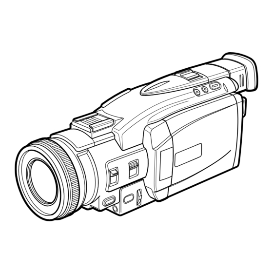
Page 6: Part Names
VL-AX1U 3. PART NAMES For details on the use of each control. Stand-by Button Front view Left view Fade Button Viewfinder Gamma/Backlight Battery Eject Lever Shoe Cover/System Shoe Button (to attach zoom microphone) LCD Monitor Diopter Scale Adjustment Knob LCD Monitor... -
Page 7: Disassembly Of The Set
VL-AX1U 4. DISASSEMBLY OF THE SET Note: Before removing the cabinet, turn off the power supply, and ascertain that the battery have been removed. Hot shoe FPC Top cover ass'y Shoe fitting Open the LCD Fitting cover DV·232C unit FPC •... - Page 8 VL-AX1U • Detach the 3 main=sub FPCs (1, 2 and 3) and 1 microphone connector. Sub PWB • Remove the 1 screw ((R)XiPSN17P03000) and 2 screws ((N)XiPSF17P02000), and pull out the sub PWB in the direc- tion of the arrow.
- Page 9 VL-AX1U VF unit • Remove the 1 screw ((Q)XiPSN17P02000) and 5 screws ((O)XiPSF17P03000), and pull out the VF unit in the direc- tion of the arrow. • Remove the 1 screw ((N)XiPSF17P02000) to detach the battery cover. Battery cover Tilt cover...
-
Page 10: Mechanism Adjustment Jigs And Parts
VL-AX1U 5. MECHANISM ADJUSTMENT JIGS AND PARTS Configuration 1. Name 5-1. Mechanism check adjustment jigs 2. Part No. 3. Code <Note: The entries of list> * Model, Uses Remarks 1. Tension gauge 4N 1. PB-use cassette 1. Torque gauge 1. Torque gauge head 1. -
Page 11: Inspection And Maintenance Items And Intervals
VL-AX1U 6. INSPECTION AND MAINTENANCE ITEMS AND INTERVALS In order to keep the mechanical section always in good condition, perform the following inspection and maintenance at regular intervals. In addition, after repair, perform the following maintenance items regardless of how long the user has been using the unit. -
Page 12: Mechanical Adjustments And Checks
VL-AX1U 7. MECHANICAL ADJUSTMENTS AND CHECKS The items discussed here relate to general on-site servicing (field servicing). Adjustments and replacements that require sophisticated facilities, jigs and technology are omitted. In addition, in order to maintain the characteristics that the unit has when it is new, not only are inspection and maintenance necessary, but it is absolutely necessary that, for example, the tape not be damaged, and always use jigs for adjustments that require them. - Page 13 VL-AX1U 7-4. Back tension torque check and adjustment in record (playback) mode Tension roller position (S guide standard) AC adapter used, with cassette controller assembly 0 ± 0.3 (1) Checking Set the torque cassette (SD-1015), and make sure in the SP record mode that...
- Page 14 VL-AX1U <REW back tension standard> (If the tension fluctuates, read its center value.) 15 ± 12mN 7-8. Checking of winding Tu reel base ratchet torque DC3V, without cassette controller assembly (Independent Mechanism) (1) Remove the cassette controller assembly, then apply DC3V to the loading motor and put the system into standby mode.
-
Page 15: Tape Running Adjustment
VL-AX1U 8. TAPE RUNNING ADJUSTMENT 8-1. Adjustment locations <Replacement parts> Adjust the height of only · T roller, arm replaced parts with the · Tu guide, arm adjusting jig. · Slide chassis Adjustment procedure 8-2 Running rough Running final Running adjustm-... - Page 16 VL-AX1U 8-4. Running rough adjustment (With cassette controller) 1) Su, Tu guide roller height adjustment Entrance side Exit side <Method and description> ±1/4 shift ±1/4 shift Normal (1) Loosen the guide roller lock screw, then tighten loosely so that the roller turns easily.
-
Page 17: Disassembly And Reassembly
VL-AX1U 9. MECHANICAL SECTION ASSEMBLY AND PARTS REPLACEMENT (DISASSEMBLY AND REASSEMBLY) Mechanical section disassembly and reassembly are explained in this section. For removal of the cabinet, etc., refer to 4. DISASSEMBLY OF THE SET. <Precautions> 1. Always replace cut washers that have been removed, for example in parts replacement, with new ones. - Page 18 VL-AX1U (6) STOP mode (5) PLAYBACK (RECORD, FF, VSF) mode The system is in the STOP (Rec Lock in CAMERA mode) The mechanism position for playback, record, FF and fast position; the S and the T pole bases are snap-fitted to the drum feed playback.
- Page 19 VL-AX1U 9-3. How to operate with the circuit board without the cassette controller assembly. In this method, if the procedure is followed incorrectly there is danger of damaging the mechanism and the tape, so except in special cases, such as when measuring the VSR torque, do not perform this procedure. Normally operate this unit with the cassette controller assembly attached.
- Page 20 VL-AX1U 9-5. Reassembly 9-5-1. Reassembly in side of the main chassis. Note) Numbers before part names are given as a guide to the order of assembly. As for greasing/oiling/cleaning places refer to the attached drawings (Grease/Oil application side of the main chassis).
- Page 21 VL-AX1U 9-5-2. Reassembly in side of the Slide chassis. Note) Numbers before part names are given as a guide to the order of assembly. As for greasing/oiling/cleaning places refer to the attached drawings (Grease/Oil application side of the slide chassis)
- Page 22 VL-AX1U 9-5-3. Main chassis assembly and slide chassis assembly assembling method (1) Enter the coupling mode. (In this position, the cam groove of the T arm operation lever in the figure is parallel to the side of the main chassis, and the poll base is slightly moved.)
- Page 23 VL-AX1U GREASE/OIL APPLICATION From rear surface side Rear surface · groove side surface Front surface · rear surface · groove From rear side surface surface side Drum base assembly Main cam Loading lever Tu loading arm S loading arm Intermediate gear angle...
-
Page 24: Adjusting The Electrical Circuits
VL-AX1U 10. ADJUSTING THE ELECTRICAL CIRCUITS Before starting the electric circuit adjustment • The adjustment methods described herein are used, in most cases, when the expendable mechanical parts, including the video head, have been replaced, at which time the electrical circuits need to be readjusted. Before adjusting the electrical circuits, make sure that the mechanism works properly (i.e., the mechanism is properly adjusted). - Page 25 VL-AX1U VL-AX1U Service jig configuration...
- Page 26 VL-AX1U [TEST POINT] (Wiring board diagram: Main Side B) TL5769 TL900 TL902 TL5750 TL5766 TL5762 TL5753 TL904 TL901 SC5701 SC5702 TL5755 TL5754 TL5775 SC900 TL905 TL906 TL5763 TL5764 TL5777 TL5773 TL5765 TL5757 TL789 TL787 TL910 TL5783 C1922 C1721 TL3319 TL5751...
- Page 27 VL-AX1U (Wiring board diagram: Sub Side A) TL2732 TL2731 TL2730 TL2728 TL3752 TL3742 T L3739 TL2724 TL3781 TL2722 TL2726 TL2721 TL2716 TL2720 TL3747 TL605 TL2719 TL2725 TL2715 TL3743 TL2718 TL2711 TL2717 TL2723 TL2710 C3750 TL3766 TL3745 TL2714 TL2712 EE level...
- Page 28 VL-AX1U [Making adjustments] Adjusting the servo system controller and related parts 1. Setting the system codes Replacement of IC705 E PROM requires the following data to be set in this order. [Procedure] Set the unit to the VCR mode and set the data for each address.
- Page 29 VL-AX1U ADJUSTING THE ELECTROMAGNETIC CONVERSION CIRCUIT SYSTEM 1. PLL VCO adjustment Mode VCR ADJ mode Procedure 1) Playback the alignment tape (or a self-recorded tape). 2) Call the adjustment mode (V-ADJ). 3) Set the address "2A" and call the data.
- Page 30 VL-AX1U ADJUSTING THE VIDEO I/O CIRCUIT SYSTEM (Wiring board diagram: Main Side B) TL783 TL5756 R2589 L501 TL5789 TL5790 T L5788 TL4405 TL4403 TL4404 C224 R2592 R2590 TL908 C2548 TL5786 R205 C2546 TL7801 R2503 TL912 TL5761 C2501 C2510 R2505 C2513...
- Page 31 VL-AX1U ADJUSTING THE LCD CIRCUIT * To make this adjustment, set the backlight switch to the "NORMAL" position. (Wiring board diagram: Main Side B) TL4440 IC501 C404 TL7800 R509 TL3320 TL3322 TL403 C507 TL5776 R520 R519 C513 R516 C515 TL416...
- Page 32 VL-AX1U 4. COM-Bias adjustment Test point LCD panel display area Address VCR ADJ 33 Mode VCR AV input Procedure 1) Input white 40% signal into the AV input. 2) Set the illuminometer (TOPCON IM-3) on the LCD panel surface. (Shut off the external light.) 3) Minimize the ripple of output waveform of illuminometer.
- Page 33 VL-AX1U (Wiring board diagram: Main Side B) C701 R1943 R1912 R1940 D1900 Q1920 C1921 TL5781 Q1938 R780 R1721 TL5770 C237 TL8843(VB) TL5780 R506 R1934 R1935 C238 R1720 VF sub-brightness R/B C451 C4702 TL3321 TL5767 C407 TL8861(BLD) R406 R411 IC202 Q1947...
- Page 34 VL-AX1U 10. VF contrast adjustment Test point TL8841(VG) Address VCR ADJ E5 Mode VCR AV input Procedure 1) Input the signal of a 3-step waveform. 2) Set VCR ADJ EB/ED to FF/00. 3) Adjust the pedestal 100% range of the waveform of TL8841 to the specified adjustment value.
- Page 35 VL-AX1U ADJUSTING THE MIC AMP CIRCUIT (Wiring board diagram: Sub Side A) TL6609(GND) 752 TL3742 T L3739 EE level TL3747 TL605 TL3743 Frequency character TL3745 TL2755 EE level TL602 Super-directional microphone TL2754 C635 TL3737 R610 Frequency character TL2752 TL2759 Super-directional microphone...
- Page 36 VL-AX1U DV INTERFACE (IEEE1394) ID SETTING This unit has a DV interface function conforming to IEEE1394. Therefore, each individual ID number must be used for each unit. Since this ID is written on the E PROM (IC302) on the head amp PWB, the ID must be newly written when replacing this IC or the head amp PWB.
- Page 37 To complete it, click on [End] in the menu screen. MODEL ID SETTING Address VCR ADJ FD, FE, FF Mode Adjustment rating The following table reference. VL-AX1U (102022) Procedure 1) Set the unit to the VCR ADJ mode. Address Data Examples •...
-
Page 38: Camera Section Adjustments
VL-AX1U 10-2. Camera Section Adjustments 10-2-1. Camera section service (1) Camera adjustment is performed after the set has been completed. (2) Subjects, measuring instruments and jigs needed for camera section service and adjustments • Gray scale chart • Frequency counter •... - Page 39 VL-AX1U 4) Operation flow FF or REW PLAY FF or REW PLAY STOP Address is selected and specified, with the data called. Then the called data are selected and fixed. The operation flows in this sequence. 5) When the adjustment is complete: Press the "CONTINUE"...
- Page 40 VL-AX1U (4) Camera signal system adjustment mode In the camera signal system adjustment mode, the automatic white balance is disabled to allow for the adjustment of the camera unit. At this time, the white balance mode is fixed at the INDOORS mode and the focus mode is switched to the manual focus mode.
- Page 41 VL-AX1U 10-2-4. Adjustment procedures Item Adjustment method (1) Auto-focus adjustment Set the unit to the auto-focus function adjustment mode and write data to the address "0001" one after another. This executed the adjustments automatically. The items to be adjusted are as listed below. Every time an adjustment is made properly, the data "00FF"...
- Page 42 VL-AX1U Adjustment method Item (4) Iris AE coarse adjustment (1) Video output is observed with the oscilloscope in the grey scale standard record state, • Measurement terminal: the data of address "0002" is rewritten, and the luminance signal level is adjusted white to 760 ±...
- Page 43 VL-AX1U Adjustment method Item (1) White balance adjustment is performed repeatedly. (7) White balance adjustment • Measurement terminal: EE output • Address: "0128" INDOOR_W/B R "012A" INDOOR_W/B R • Measuring instrument: Vector scope • Object: Grey scale • Data variation width: "0000"...
- Page 44 VL-AX1U Adjustment method Item (12) Iris AE adjustment (1) Set the unit to the normal operation mode (write the data " FF" to the address • Measurement terminal: "0000"). S terminal luminance signal output (2) Video output is observed with the oscilloscope in the grey scale standard record (75 Ω...
-
Page 45: Useful Tips
VL-AX1U 11. USEFUL TIPS (PROBLEMS DIFFER FROM THOSE FOUND ON VHS OR 8MM DECKS BECAUSE THE SIGNALS ARE DIGITALLY PROCESSED.) Camera (EE mode) VCR (EE mode) Camera (REC mode) VCR (PB mode) Picture fails to appear when tape Picture fails... -
Page 46: Signal Flow Diagrams
VL-AX1U 12. SIGNAL FLOW DIAGRAMS 12-1. EE MODE FLOW (VIDEO) WAVEFORM DIAGRAM (DURING COLOR BAR RECORDING) IC4401 249pin Y/YC Output CAM ADIN CH1=500mV 20µs/d DC P*10 IC201 CAM ENGINE IC4401 170pin ZYP3 Input 5ms/d CH1=1V DC P*10 CZYP CZCP 43 41... - Page 47 VL-AX1U WAVEFORM DIAGRAM 12-3. FLOW IN PB MODE (VIDEO) (DURING COLOR BAR PLAYBACK) IC3401 39pin PBDATA Input IC3401 32pin Output HEAD AMP 5ms/d 5ms/d CH1=500mV CH1=500mV DC P*10 DC P*10 PB_DATA B TO B SC3301 PB_DATA IC3401 EQ/PLL IC3401 44pin Input...
- Page 48 VL-AX1U 12-5. FLOW IN PB MODE (AUDIO) WAVEFORM DIAGRAM (1.6 kHz SINE WAVE) From IC3404 same as in Video 10µs/d CH1=1V PB system DC P*10 IC452 REC/PB ENGINE DODAT 16Bit ADC/DAC IC1602 AUD-R_DA_OUT AUD-L_DA_OUT IC601 AUDIO I/O Headphone AUDIO-R_IN/OUT Jack...
-
Page 49: Block Diagrams
VL-AX1U 13. BLOCK DIAGRAMS 13-1. SYSTEM BLOCK DIAGRAM... - Page 50 VL-AX1U 13-2. CAMERA SECTION BLOCK DIAGRAM...
- Page 51 VL-AX1U 13-3. VIO ENGINE SECTION BLOCK DIAGRAM...
- Page 52 VL-AX1U 13-4. REC/PB SECTION BLOCK DIAGRAM...
- Page 53 VL-AX1U 13-5. AUDIO/DIGITAL OUTPUT SECTION BLOCK DIAGRAM...
- Page 54 VL-AX1U 13-6. CAMERA CIRCUIT BLOCK DIAGRAM...
- Page 55 VL-AX1U - M E M O -...
-
Page 56: Schematic Diagrams
VL-AX1U 14. SCHEMATIC DIAGRAMS 14-1. OVERALL SCHEMATIC DIAGRAM 56~57... - Page 57 VL-AX1U 14-2. CAMERA ENGINE SCHEMATIC DIAGRAM 58~59...
- Page 58 VL-AX1U 14-3. REC/PB ENGINE SCHEMATIC DIAGRAM 60~61...
- Page 59 VL-AX1U 14-4. CMC SCHEMATIC DIAGRAM 62~63...
- Page 60 VL-AX1U 14-5. MEC/SYS MiCON SCHEMATIC DIAGRAM 64~65...
- Page 61 VL-AX1U 14-6. POWER2 SCHEMATIC DIAGRAM å AND SHADED COMPONENTS=SAFETY RELATED PARTS å å å å å 66~67...
- Page 62 VL-AX1U 14-7. RINKAKU SCHEMATIC DIAGRAM 68~69...
- Page 63 VL-AX1U 14-8. VIDEO I/O SCHEMATIC DIAGRAM 70~71...
- Page 64 VL-AX1U 14-9. MOTOR DRIVER SCHEMATIC DIAGRAM 72~73...
- Page 65 VL-AX1U 14-10. POWER1 SCHEMATIC DIAGRAM 74~75...
- Page 66 VL-AX1U 14-11. LENS DRIVER SCHEMATIC DIAGRAM 76~77...
- Page 67 VL-AX1U 14-12. LCD IF SCHEMATIC DIAGRAM 78~79...
- Page 68 VL-AX1U 14-13. CONNECTION(B-B) SCHEMATIC DIAGRAM 80~81...
- Page 69 VL-AX1U 14-14. EQ/PLL SCHEMATIC DIAGRAM 82~83...
- Page 70 VL-AX1U 14-15. VIDEO I/O ENGINE SCHEMATIC DIAGRAM 84~85...
- Page 71 VL-AX1U 14-16. DAC SCHEMATIC DIAGRAM 86~87...
- Page 72 VL-AX1U 14-17. CARD CONN SCHEMATIC DIAGRAM 88~89...
- Page 73 VL-AX1U 14-18. V/F SCHEMATIC DIAGRAM 90~91...
- Page 74 VL-AX1U 14-19. AUDIO I/O SCHEMATIC DIAGRAM 92~93...
- Page 75 VL-AX1U 14-20. CARD MICON SCHEMATIC DIAGRAM 94~95...
- Page 76 VL-AX1U 14-21. MIC AMP SCHEMATIC DIAGRAM 96~97...
- Page 77 VL-AX1U 14-22. CCD SCHEMATIC DIAGRAM 98~99...
- Page 78 VL-AX1U 14-23. TG SCHEMATIC DIAGRAM 100~101...
- Page 79 VL-AX1U 14-24. CDS SCHEMATIC DIAGRAM 102~103...
- Page 80 VL-AX1U 14-25. LCONN SCHEMATIC DIAGRAM 104~105...
- Page 81 VL-AX1U 14-26. LCD SCHEMATIC DIAGRAM å AND SHADED COMPONENTS=SAFETY RELATED PARTS å 106~107...
- Page 82 VL-AX1U 14-27. HEAD AMP SCHEMATIC DIAGRAM 108~109...
-
Page 83: Semiconductor Lead Identification
VL-AX1U 15. SEMICONDUCTOR LEAD IDENTIFICATION HN2A01FU 2SA1989R 2SC4627CD NDS355AN FC117 UN9214 3LN01S HN1B04FU 2SC4738Y RN4984 HN2C01FU FMMT717 CPH3109 RN4986 2SC5383F CPH3206 RN4990 XP05534 2SA1588Y RT1N441U MC2852 RN1704 TA75S01F 2SC4944Y TC7S08U TC7S04U TCSZ04U FMG12 NDS332P MA132WK CPH6702... - Page 84 VL-AX1U HVU359TR KV1812K EX1394CE HVU362 HVC359TR MB88344F BH7277KV BH7275KV LB11990W MB3881 LV4051AT MB8346BV NJM2538B LV4051AT NJM2904V ADC08351 NJM2902V IXA193WJ IX0707TA NJM2535V NJM2143R M24C04W6 IX0809TA SN2G53CT TLC2940 NJM2143R IX0785TA NJU7015R...
- Page 85 VL-AX1U 16. PRINTED WIRING BOARD ASSEMBLIES MAIN PWB SIDE A 112~113...
- Page 86 VL-AX1U SIDE B 114~115...
- Page 87 VL-AX1U SUB PWB SIDE A TL2732 TL2731 TL2730 TL2728 TL3752 TL3742 T L3739 TL2724 TL3781 TL2722 TL2726 TL2721 TL2716 TL2720 TL3747 TL2719 TL2725 TL2715 TL3743 TL2718 TL2711 TL2717 TL2723 TL2710 C3750 TL3766 TL2714 TL3745 TL2712 TL602 TL2709 TL2708 TL2727 L603...
- Page 88 VL-AX1U SIDE B SC3704 SC3705 R3802 R3805 R3806 R3807 SC3701 TL2755 TL2754 TL2752 TL2759 TL6609 TL2753 TL2757 TL2756 TL2758 TL6601 SC3703 TL6611 TL6608 TL6610 BAT3750 SC3702 P6601...
- Page 89 VL-AX1U CAMERA PWB SIDE A R1003 R1001 C1007 C1003 R1005 C1005 R1007 TL104 C1018 C1004 C1008 R1004 R1006 R1002 C1006 IC1002 R1016 TL1021 TL1013 R1017 R1018 R1012 TL1012 R1009 R1010 C1012 Q1001 Q1002 C1017 Q1003 TL1014 TL13 TL11 TL12 TL10...
- Page 90 VL-AX1U CCD PWB SIDE A C116 C111 R103 C112 R115 C104 IC101 C106 C101 C103 R116 C102 C120 R120 C115 C114 C118 C1002 RMC1002...
- Page 91 VL-AX1U LCD PWB SIDE A...
- Page 92 VL-AX1U HEAD AMP PWB Component Side SIDE A R332 C320 C315 R330 R331 R333 R321 R308 C322 C304 R320 Q302 C331 C307 C330 R318 P306 C305 R312 C324 R323 C319 C311 R304 R325 C333 Q303 C301 C327 R324 C342 C332...
- Page 93 VL-AX1U Component Side SIDE B C345 L301 C303 Wiring Side SIDE B...
-
Page 94: Printed Wiring Board Assemblies
VL-AX1U 17. REPLACEMENT PARTS LIST/ Ref. No. Part No. Description Code Ref. No. Part No. Description Code EXPLODED VIEWS DUNTKB365QA00 MAIN PWB UNIT ELECTRICAL PARTS LIST INTEGRATED CIRCUITS å CP1 VHiCCP2B25/-1 CCP2B25, 1.25A 24V Parts marked with " å " are important for maintaining the safety of the å... - Page 95 VL-AX1U Ref. No. Part No. Description Code Ref. No. Part No. Description Code Q910 VSNDS355AN/-1 NDS355AN X4451 RCRSC0167TAZZ Crystal, CRSC0167TA Q911 VSCPH6702++-1 CPH6702++ Q1401 VSRT1N441U/-1 RT1N441U COILS AND TRANSFORMER Q1402 VS2SC5376B+-1Y 2SC5376B+ FL403 RFiLC0164TAZZ Filter Q1403 VS2SC5376B+-1Y 2SC5376B+ FL501 RFiLZ0169TAZZY...
- Page 96 VL-AX1U Ref. No. Part No. Description Code Ref. No. Part No. Description Code C711 VCKYCZ1HB102K 1000p 50V Ceramic C212 VCKYCZ1AF104Z 10V Ceramic C712 VCKYCY0JB105K 6.3V Ceramic C213 VCSAPR0JJ106M 6.3V Tantalum C713 VCKYCZ1HB102K 1000p 50V Ceramic C215 VCKYCZ1AF104Z 10V Ceramic C716...
- Page 97 VL-AX1U Ref. No. Part No. Description Code Ref. No. Part No. Description Code C961 VCKYCZ1HB222K 2200p 50V Ceramic C1717 VCKYCZ1AF104Z 10V Ceramic C962 RC-KZ0072TAZZ 25V Ceramic C1718 VCKYCZ1AF104Z 10V Ceramic C963 RC-KZ0072TAZZ 25V Ceramic C1719 VCKYCY0JF105Z 6.3V Ceramic C964 VCKYTV1CF105Z...
- Page 98 VL-AX1U Ref. No. Part No. Description Code Ref. No. Part No. Description Code C3424 VCKYCZ1CB103K 0.01 16V Ceramic C7401 RC-KZ0083TAZZ 10V Ceramic C3425 VCSATA0JJ336M 6.3V Tantalum C7402 VCKYCZ1CB103K 0.01 16V Ceramic C3426 VCKYCZ1CB103K 0.01 16V Ceramic C7403 VCKYCZ1CB103K 0.01 16V Ceramic...
- Page 99 VL-AX1U Ref. No. Part No. Description Code Ref. No. Part No. Description Code R414 VRS-CZ1JF000J 1/16W Metal Oxide R752 VRS-CZ1JF103J 10k 1/16W Metal Oxide R416 VRS-CZ1JF823J 82k 1/16W Metal Oxide R753 VRS-CZ1JF103J 10k 1/16W Metal Oxide R418 VRS-CZ1JF101J 100 1/16W Metal Oxide...
- Page 100 VL-AX1U Ref. No. Part No. Description Code Ref. No. Part No. Description Code R951 VRS-CZ1JF102J 1/16W Metal Oxide R1602 VRS-CZ1JF000J 1/16W Metal Oxide R952 VRS-CZ1JF223D 22k 1/16W Metal Oxide R1701 VRK-SA1JF100J 1/16W R953 VRS-CZ1JF105J 1/16W Metal Oxide Metal Composition R954...
- Page 101 VL-AX1U Ref. No. Part No. Description Code Ref. No. Part No. Description Code R3402 VRS-CZ1JF000J 1/16W Metal Oxide R2501 VRS-CZ1JF103J 10k 1/16W Metal Oxide R3403 VRS-CZ1JF472J 4.7k 1/16W Metal Oxide R2502 VRS-CZ1JF104J 100k 1/16W Metal Oxide R2503 VRS-CZ1JF4R7J 1/16W Metal Oxide...
- Page 102 VL-AX1U Ref. No. Part No. Description Code Ref. No. Part No. Description Code R4415 VRS-CZ1JF000J 1/16W Metal Oxide R7810 VRS-CZ1JF273J 27k 1/16W Metal Oxide R4416 VRS-CZ1JF393J 39k 1/16W Metal Oxide R7811 VRS-CZ1JF823J 82k 1/16W Metal Oxide R4417 VRS-CZ1JF273J 27k 1/16W Metal Oxide...
- Page 103 VL-AX1U Ref. No. Part No. Description Code Ref. No. Part No. Description Code C641 VCKYCY0JF105Z 6.3V Ceramic DUNTK3120QA03 C642 VCSATE0JJ107M 6.3V Tantalum SUB PWB UNIT C644 VCKYCY1CB683K 0.068 16V Ceramic C645 VCKYCZ1AF104Z 10V Ceramic C646 VCKYCY0JF105Z 6.3V Ceramic INTEGRATED CIRCUITS...
- Page 104 VL-AX1U Ref. No. Part No. Description Code Ref. No. Part No. Description Code C6652 VCKYCY1CB473K 0.047 16V Ceramic R3722 VRS-CZ1JF102J 1/16W Metal Oxide C6653 VCKYCY1EB223K 0.022 25V Ceramic R3723 VRS-CZ1JF102J 1/16W Metal Oxide C6654 VCKYCY1AB224K 0.22 10V Ceramic R3724 VRS-CZ1JF102J...
- Page 105 VL-AX1U Ref. No. Part No. Description Code Ref. No. Part No. Description Code R6617 VRS-CZ1JF103J 10k 1/16W Metal Oxide IC1002 VHiNJM2112V-1 NJM2112V, Op-Amp R6618 VRS-CZ1JF223J 22k 1/16W Metal Oxide TRANSISTORS R6619 VRS-CZ1JF183J 18k 1/16W Metal Oxide R6620 VRS-CZ1JF333J 33k 1/16W Metal Oxide...
- Page 106 VL-AX1U Ref. No. Part No. Description Code Ref. No. Part No. Description Code C1015 VCKYCZ1HF103Z 0.01 50V Ceramic DUNTK3122QA01 C1016 VCSATA0JJ156M 6.3V Tantalum LCD PWB UNIT C1017 VCKYCZ1HF103Z 0.01 50V Ceramic C1018 VCKYCY1CF104Z 16V Ceramic INTEGRATED CIRCUIT RESISTORS IC9800 VHiTA75S01F-1...
- Page 107 VL-AX1U Ref. No. Part No. Description Code Ref. No. Part No. Description Code R9800 VRS-CZ1JF121J 120 1/16W Metal Oxide C329 VCSATA1AJ106M 10V Tantalum R9801 VRS-CZ1JF152J 1.5k 1/16W Metal Oxide C330 VCKYCZ1HF103Z 0.01 50V Ceramic R9802 VRS-CZ1JF152J 1.5k 1/16W Metal Oxide...
- Page 108 VL-AX1U Ref. No. Part No. Description Code Ref. No. Part No. Description Code LX-WZ1071GE02 CW ø 0.7 ø 1.8t0.1 MECHANISM PARTS LX-WZ1104GE06 CW ø 0.7 ø 2.2t0.25 LX-WZ1029GE00 CW ø 1.2 ø 3t0.25 LCHSM0181GEZZ Main Chassis Ass’y LZ-WZ1105GE00 W ø 1.2 ø 2.5t0.13...
- Page 109 VL-AX1U Ref. No. Part No. Description Code Ref. No. Part No. Description Code CABINET PARTS LIST 3-1-6 MSPRP0222TAFJ VF Diopter Adjusting Spring CCABA6231TAK1 Cabinet A Ass’y 3-1-7 PLNSV0009TAN3 VF Lens 3-1-8 PSHEP0245TAZZ VF Diopter Covering Sheet AD DCOVA1798TAK2 Battery Cover Service...
- Page 110 VL-AX1U Ref. No. Part No. Description Code Ref. No. Part No. Description Code PSPAZ0421TAZZ Sound Insulation Spacer C AB XiPSF17P03000 M1.7 X 3 Small Screw PSPAZ0422TAZZ Sound Insulation Spacer D AC (Black) PLNSA0147TAN1 Lens Unit XiPSF17P04000 M1.7 X 4 Small Screw...
- Page 111 VL-AX1U Ref. No. Part No. Description Code Ref. No. Part No. Description Code SUPPLIED ACCESSORIES ACCESSORIES å QACCD0031TAPZ AC Cable å UADP-0333TAZZ AC Adapter CDSKA0080TA01 SD Card(8M) GCOVA1767TASA Lens Hood GCOVH1270TASA Lens Cap QCNW-1914TAZZ PC Cable QCNW-1957TAZZ DC Cable QCNW-1979TAZZ...
- Page 112 VL-AX1U MECHANISM CHASSIS EXPLODED VIEW Ref. No. Part No. Description Code Ref. No. Part No. Description Code 1pc. 411~ 411~ +0.5 +0.5...
- Page 113 VL-AX1U CABINET EXPLODED VIEW Ref. No. Part No. Description Code Ref. No. Part No. Description Code 5-1-8 5-1-9 3-17 5-1-3 3-1-2 3-14 5-1-5 5-1-7 3-15 3-10 3-11 3-13 3-1-7 5-1-10 3-1-4 5-10 5-1-6 3-16 3-1-6 5-11 3-1-5 5-1-12 3-12 3-1-3...
- Page 114 VL-AX1U CASSETTE CONTROL EXPLOOD VIEW Ref. No. Part No. Description Code Ref. No. Part No. Description Code 4±0.5 8.5±0.5 CAMERA UNIT EXPLOOD VIEW...
- Page 115 VL-AX1U VL-AX1U SERVICE JIG SPECIFICATIONS Ref. No. Part No. Description Code Ref. No. Part No. Description Code 1-1. Adjusting jigs for checking the mechanism Name New part Type number, Application Part code Code PB-use cassette torque meter 1mN·m/1.5mN·m 9DASD-1015 Torque gauge...
-
Page 116: Packing Of The Set
VL-AX1U 18. PACKING OF THE SET Ref. No. Part No. Description Code Ref. No. Part No. Description Code RMiCC0105TAZZ UBATL0011TAZZ QCNW-1914TAZZ (Zoom Microphone) (Lithium Battery(X2)) (PC Cable) CDSKA0080TA01 (SD Card(8M)) åUADP-0333TAZZ QCNW-1957TAZZ (AC Adapter) (DC Cable) GCOVA1767TASA (Lens Hood) SPAKF0291TAZZ... - Page 117 Part No. Description Code © COPYRIGHT 2002 BY SHARP CORPORATION ALL RIGHTS RESERVED. No part of this publication may be reproduced, stored in a retrieval system, or transmitted in any form or by any means, electronic, mechanical, photocopying, recording, or otherwise, without prior written permission of the publisher.