Table of Contents
Advertisement
SERVICE MANUAL
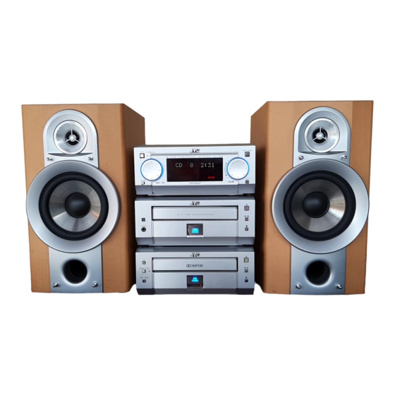
MICRO COMPONENT SYSTEM
REMOTE CONTROL RM-SUXG6E
PANEL
OPEN/CLOSE
DIMMER
ACTIVE
SLEEP
BASS EX.
CLOCK/TIMER
BASS
TREBLE
FM MODE
PLAY MODE
REPEAT
AUTO PRESET
TITTLE/EDIT
ENTER
PTY/EON
DISPLAY
/CHARA.
CANCEL
UP
<
>
SET
DOWN
MD
AUX
TAPE
CD
FM/AM
+
VOLUME
–
Unit composition
Contents
STEREO AMPLIFIER
CD / TUNER
CASSETTE DECK
SPEAKER SYSTEM
< ATTENTION >
When this model is repaired, a part of unit of "UX-G6/FS-G6" is necessary.
Contents
Safety precautions ----------------------------------- 1-2
Important for laser products ----------------------- 1-3
Preventing static electricity ------------------------- 1-4
Attention at repair reception ----------------------- 1-5
Instructions (UX-G6) --------------------------------- 1-6 - 15
AX-UXG6 ----------------------------------------------- 2-1
UX-G6/FS-G6
STANDBY/ON
M I C R O
C O M P O N E N T
S Y S T E M
U X - G 6 R
FM/AM
MULTI
JOG
VOLUME
MOS - FET
1 B I T
P • E • M
D • D • C O N V E R T E R
PHONES
COMPACT
DIGITAL AUDIO
DOLBY B NR
REC PAUSE
AUTO
REVERSE
REC
Model Name
AX-UXG6
XT-UXG6
TD-UXG6
SP-UXG6
COPYRIGHT
2000 VICTOR COMPANY OF JAPAN, LTD.
OPEN/CLOSE
AUX
(Please refer to page 1-5)
XT-UXG6 ----------------------------------------------- 2-11
TD-UXG6 ----------------------------------------------- 2-31
SP-UXG6 ----------------------------------------------- 2-46
Standard schematic diagrams -------------------- 2-47
Printed circuit boards -------------------------------- 2-56 - 60
Parts List ------------------------------------------------ 3-1 - 31
UX-G6/FS-G6
Area Suffix (UX-G6)
UB ............. Hong Kong
UP ..................... Korea
U ............... Other Areas
Area Suffix (FS-G6)
J ......... U.S.A./ Canada
We will separately issue the
parts list of J version.
No.20808
Feb. 2000
Advertisement
Table of Contents

Related Manuals for JVC UX-G6


Summary of Contents for JVC UX-G6
- Page 1 CASSETTE DECK TD-UXG6 SPEAKER SYSTEM SP-UXG6 < ATTENTION > When this model is repaired, a part of unit of “UX-G6/FS-G6” is necessary. (Please refer to page 1-5) Contents Safety precautions ----------------------------------- 1-2 XT-UXG6 ----------------------------------------------- 2-11 Important for laser products ----------------------- 1-3...
-
Page 2: Safety Precautions
UX-G6/FS-6G Safety Precautions 1. This design of this product contains special hardware and many circuits and components specially for safety purposes. For continued protection, no changes should be made to the original design unless authorized in writing by the manufacturer. -
Page 3: Important For Laser Products
UX-G6/FS-G6 Important for laser products 5.CAUTION : If safety switches malfunction, the laser is able 1.CLASS 1 LASER PRODUCT to function. 2.DANGER : Invisible laser radiation when open and inter 6.CAUTION : Use of controls, adjustments or performance of lock failed or defeated. Avoid direct exposure to beam. -
Page 4: Preventing Static Electricity
UX-G6/FS-G6 Preventing static electricity Electrostatic discharge (ESD), which occurs when static electricity stored in the body, fabric, etc. is discharged, can destroy the laser diode in the traverse unit (optical pickup). Take care to prevent this when performing repairs. 1.1. Grounding to prevent damage by static electricity Static electricity in the work area can destroy the optical pickup (laser diode) in devices such as DVD players. - Page 5 Attention at repair reception < ATTENTION > When this model is repaired, a part of unit of "UX-G6/FS-G6" is necessary. A necessary unit is described to rear panel. Please keep the unit from the customer together when you repair this model.
- Page 6 UX-G6/FS-G6 Instructions (UX-G6) Mains (AC) Line Instruction (not applicable for Europe, U.S.A., Canada, Australia and U.K.) Instrucción sobre la línea de la red (CA) (no aplicable para Europa, EE.UU., Canadá, Australia, ni el Reino Unido) MICRO COMPONENT SYSTEM UX-G6 Consists of AX-UXG6, XT-UXG6, TD-UXG6, and SP-UXG6.
- Page 7 – G-3 – – G-4 – Contents Introduction We would like to thank you for purchasing one of our JVC products. Introduction ............1 Playing Back a Tape ........... 20 Before operating this micro component system, read this manual carefully About This Manual ...............
-
Page 8: Location Of The Buttons And Controls
After unpacking, check to be sure that you have all the 2 CLOCK/TIMER button (10, 25) following items. UX-G6 micro component system consists of three units, 3 ACTIVE BASS EX. (extension) button (12) The number in the parentheses indicates the quantity of the... -
Page 9: Basic Settings
You can also connect the MD recorder XM-G6 (not Supplied FM antenna You can connect the speakers using the speaker cords. supplied), specifically designed for UX-G6. This unit will complete UX-G6 micro component system. 2, 3 When you connect and use this unit, refer to the Instructions supplied with it for details. -
Page 10: Common Operations
You can use the sliding panel to enable advanced operations You can listen to an external equipment such as MD recorder, REMOTE CONTROL RM-SUXG6E PANEL PANEL features provided for UX-G6 micro component system. VCR, and other auxiliaries. OPEN/CLOSE DIMMER OPEN/CLOSE... -
Page 11: Playing Back A Cd
UX-G6/FS-G6 Playing Back a CD Continued The tuned station in step 1 is now stored in the Preset Station preset channel selected in step 3. Buttons behind the sliding panel You are possibly not allowed to use the feature until... -
Page 12: Playing Back A Tape
UX-G6/FS-G6 Playing Back a Tape Continued Playing at Random — Random Play Repeating Tracks — Repeat Play DISPLAY /CHARA. CANCEL Buttons behind the sliding panel The tracks of the loaded CD will play in no special order You can have the entire disc, the programed tracks, or the (at random) when you select this mode. -
Page 13: Using The Timers
Press DOLBY B NR button before recording to as follows, CD application on UX-G6 system can be recorded with a reduce frequency response noise. Cassette deck unit will stop after leaving a non- simple, one-touch operation. -
Page 14: Maintenance And Additional Information
UX-G6/FS-G6 Continued Rotate MULTI JOG dial ( < / > button on the remote Rotate MULTI JOG dial ( < / > button on the remote Using Sleep Timer Timer Priority control also available) to select the minute of the control also available) to adjust the volume level, then timer-off time, then press SET button. -
Page 15: Troubleshooting
UX-G6/FS-G6 Troubleshooting Specifications Stereo Amplifier AX-UXG6 Speaker System SP-UXG6 If you are having a problem with your system, check this list for a possible solution before calling for service. If you cannot solve the problem from the hints given here, or the units has been physically damaged, call a qualified... - Page 16 UX-G6/FS-G6 << M E M O >> 1-16...
- Page 17 UX-G6/FS-G6 AX-UXG6...
- Page 18 UX-G6/FS-G6 Disassembly method (AX-UXG6) Removing the top cover (See Fig.1) 1. Remove the two screws A and the four screws B attaching the top cover. 2. Remove the top cover from behind in the direc- tion of the arrow while pulling the sides outward.
- Page 19 UX-G6/FS-G6 Front sub panel assembly Removing the front sub panel assembly (See Fig.6 to 8) • Prior to performing the following procedure, remove the top cover and the front panel assem- CN704 bly. 1. Disconnect the card wire from connector CN704 on the back of the front sub panel assembly.
- Page 20 UX-G6/FS-G6 Regulator board Removing the regulator board (See Fig.10) • Prior to performing the following procedure, remove the top cover. 1. Disconnect the card wire from connector CN908 on the main board. CN906 Main board 2. Disconnect the harness from connector CN906 CN908 on the main board.
- Page 21 UX-G6/FS-G6 Removing the main board and the heat sink CN907 (See Fig.11 to 18) CN906 • Prior to performing the following procedure, remove CN908 the top cover and the rear cover. CN905 1. Disconnect the harness or card wire from connector...
- Page 22 UX-G6/FS-G6 Removing the slide gear motor assembly (See Fig.19 to 21) • Prior to performing the following procedure, remove the top cover and the regulator board . Slide gear motor assembly 1. Disconnect the harness from connector CN907 on the main board.
- Page 23 UX-G6/FS-G6 Front panel assembly <Front panel assembly> Removing the front board. (See Fig.22 to 24) • Prior to performing the following procedure, remove the top cover Multi-jog dial Volume dial and the front panel assembly. Fig. 22 1. Remove the seven screws R attaching the front...
- Page 24 UX-G6/FS-G6 Description of major ICs LB1641 (IC901) : DC Motor driver 1. Pin Layout GND OUT1 P1 IN2 VCC1 VCC2 P2 OUT2 2. Pin Functions Input Output Mode OUT1 OUT2 Brake CLOCKWISE COUNTER-CLOCKWISE Brake...
- Page 25 UX-G6/FS-G6 UPD780023 (IC701) : System control 1.Pin layout 2.Key matrix 64 ~ 49 KEYO1 KEYO2 KEYO3 KEYI1 CLOCK/TIMER TITLE/EDIT KEYI2 DISPLAY/CHARA. KEYI3 PLAYMODE CANCEL ENTER 17 ~ 32 KEYI4 RECMODE 3.Pin function Pin No. Symbol Function JOG1A,B Rotary encoder input from JOG1(JS701)
- Page 26 UX-G6/FS-G6 Block diagram (AX-UXG6) CN908 CN704 2-10...
- Page 27 UX-G6/FS-G6 XT-UXG6 2-11...
- Page 28 UX-G6/FS-G6 Disassembly method Top cover (XT-UXG6) Removing the top cover (See Fig.1) 1. Remove the two screws A and the four screws B attaching the top cover. Remove the top cover in the direction of the arrow while pulling it.
- Page 29 UX-G6/FS-G6 Removing the front panel assembly Rear panel (See Fig.5 and 6) • Prior to performing the following procedure, remove the top cover. 1. Remove the seven screws E attaching the rear joint c joint c panel on the back of the body and release the two joints "c"...
- Page 30 UX-G6/FS-G6 CN451 Removing the analog in/digital out board and the relay board (See Fig.8 to 10) • Prior to performing the following procedure, remove the top cover, the rear panel and the system control board. 1. Cut the tie band fixing the harness on the side of the body.
- Page 31 UX-G6/FS-G6 Removing the CD mechanism assembly main & CD servo board (See Fig.12 to 14) • Prior to performing the following procedure, remove the top cover, the front panel assembly, the rear panel, the system control board and the analog in/digital out board.
- Page 32 UX-G6/FS-G6 << CD Mechanism section >> Removing the traverse mechanism CD tray 1. Remove the tray stopper screw "A" on the CD tray 2. The CD tray is drawn out in the direction of the arrow. Tray stopper screw A...
- Page 33 UX-G6/FS-G6 Removing the spindle motor 1. Remove the traverse mechanism 2. The turntable is removed from the spindle motor, and remove two screws D which is the fixation of the spindle motor. 3. Remove the screw which is the fixation of the...
-
Page 34: Flow Of Functional Operation Until Toc Read
UX-G6/FS-G6 Flow of functional operation until TOC read Check Point Slider turns REST Play Key Power ON Confirm that the voltage at the pin5 SW ON. of CN440 is "H"\"L"\"H". Automatic tuning of TE offset Check that the voltage at the... - Page 35 UX-G6/FS-G6 Maintenance of laser pickup Replacement of laser pickup (1) Cleaning the pick up lens Before you replace the pick up, please try to Turn off the power switch and,disconnect the clean the lens with a alcohol soaked cotton power cord from the ac outlet.
- Page 36 UX-G6/FS-G6 Description of major ICs AN8806S (IC462) : RF & Servo AMP 1.Pin layout PDAC PDBD LDON PDER PDFR TBAL RF OUT FBAL RF IN C.AGC EF OUT C.ENV TE OUT C.EA CROSS CS BDO TE BPF VDET CS BRT...
- Page 37 UX-G6/FS-G6 3. Pin function Pin No. Symbol Description APC amp input terminal APC amp output terminal LD ON APC ON/OFF control terminal Connect to ground Power supply Inverse input pin for RF amp RFamp output RF OUT RF IN RF input Connecting pin of AGC loop filter C.AGC...
- Page 38 UX-G6/FS-G6 BA6897FP (IC463) : 4channel driver TC9164AN (IC432) : Analog switch 1.Function D.BUF Switch to On/Off of S1 to S8 by control of LSI. CH1-OUTA D.BUF 2.Terminal Lay out & Block Diagram CH1-OUTB CH4-OUTA TC9164AN D.BUF CH1-INA Level CH4-OUTB Level...
- Page 39 UX-G6/FS-G6 MN35511AL (IC461) : Digital servo & Processor 1.Pin layout 2.Block diagram VCOF2 AVDD2 DEMP/TEST2 OUT2D 8tims OUT2C Over VCO2 Sampling Method LRCKI BCKI OUT1D Digital SDATAI Filter OUT1C IOSEL AVSS2 BLKCK CLDCK FLAG SBCK SBCK2 IP FLAG SUBC DEMPO...
- Page 40 UX-G6/FS-G6 3. Pin function symbol I/O symbol I/O Description Description Bit clock output for SRDATA Non connect BCLK TOFS LRCK Identification signal output of Lch and Rch PLAY Non connect SRDATA WVEL Non connect Serial data output DVDD1 Power supply (Digital)
- Page 41 UX-G6/FS-G6 LC72136N (IC2) : PLL frequency synthesizer 1. Pin layout FM/AM LPFOUT LPFIN CLOCK FM/ST/VCO FMIN AM/FM AMIN IFCONT SDIN IFIN 2. Block diagram Phase Reference Detector Driver Charge Pump Swallow Counter Swallow Counter 1/16,1/17 4bit 1/16,1/17 4bit Unlock Detector...
- Page 42 UX-G6/FS-G6 TA2057N (IC1) : FM/AMP IF AMP & Detector 1.Block Diagrams IF IN Vstb IF IN QUAD FM OUT AM OUT MPX IN LPF 1 LPF 2 L OUT DIVIDE MUTE DECODE LEVEL AM/FM MONO BUFF IF REQ BUFF IF OUT...
- Page 43 UX-G6/FS-G6 TA7439 (IC435) : Rear/center volume 1.Pin layout CREF DIG GND TREBLE(R) AGND TREBLE(L) ROUT MIN(L) LOUT MOUT(L) R-IN4 BOUT(L) R-IN3 BIN(L) R-IN2 BOUT(R) R-IN1 BIN(R) L-IN1 MOUT(R) L-IN2 MIN(R) L-IN3 L-IN4 MUXOUTR MUXOUTL TDA7439 2.Block diagram L-IN1 SPEAKER MIDLE...
- Page 44 UX-G6/FS-G6 UPD784214AFG501 (IC501) : Sysem controller 1.Pin layout 80 ~ 51 1 ~ 30 2. Pin function Symbol Description Symbol Description PERIODO Tuner PLL control output AVSS Connect to GND Stereo indicator signal input CD/OPT Digital input selector TCLOCK Tuner PLL control output...
- Page 45 UX-G6/FS-G6 Block diagram (XT-UXG6) CN457 CN435 CN433 CN432 CN431 CN451 CN453 CN454 CN503 CN504 CN439 CN440 CN506 CN505 2-29...
- Page 46 UX-G6/FS-G6 << M E M O >> 2-30...
- Page 47 UX-G6/FS-G6 TD-UXG6 2-31...
- Page 48 UX-G6/FS-G6 Disassembly method Top cover (TD-UXG6) Removing the top cover (See Fig.1) 1. Remove the two screws A and the four screws B attaching the top cover. 2. Remove the top cover from behind in the direc- tion of the arrow while pulling the sides outward.
- Page 49 UX-G6/FS-G6 Rear panel Removing the rear panel (See Fig.6 and 7) • Prior to performing the following procedure, remove the top cover. 1. Remove the three screws E attaching the rear Joint c Joint c panel on the back of the body and release the two joints "c"...
- Page 50 UX-G6/FS-G6 Connector on the Removing the loading mechanism board/ motor board Dolby board (See Fig.9) • Prior to performing the following procedure, remove the top cover and the rear panel. CN632 1. Disconnect the harness from the connector on the motor board in the cassette mechanism.
- Page 51 UX-G6/FS-G6 <<Cassette Mechanism Section>> Detaching the cassette loading mechanism (Fig. 1 to 3) Loading gear 1. Turn the loading drive gear in the direction shown by the arrow so that the head relay board can be re- moved. 2. Remove the screw A securing the head relay board (to protect the head wire).
- Page 52 UX-G6/FS-G6 Detaching the capstan motor (Fig. 4) 1. Disconnect the capstan motor wiring. 2. Remove the two screws F securing the capstan motor. Fig. 4 Detaching the mechanism (Fig. 5 to 11) 1. Head block Remove the two screws G securing the head block (when installing, attach to the return gear arm).
- Page 53 UX-G6/FS-G6 4. Leaf switch replacement Unsolder Remove the two screws H securing the leaf switch board. Fig. 8 5. Mechanism base (1) Pull out the reel disk. Guide (2) Detach the brake arm. Pull up the brake arm by releasing the stopper Reel idle gear on the brake arm shaft.
- Page 54 UX-G6/FS-G6 Assembling (Figs. 11 to 13) 1. Set the cam gear in the position shown in the figure. 2. Set the spring as shown in the figure. 3. Set the solenoid plunger (shaft). 4. Attach to the mechanism base. 5. Slide the head return slider (white plastic) in the direction shown by the arrow to position the stud.
- Page 55 UX-G6/FS-G6 Main adjustment 1.Measuring instruments required for adjustment (1) Low frequency oscillator (6) 600 resistors and so forth (for attenuator This oscillator should be capable of outputting matching) 0dB (0.775V) at the 600W terminal at an (7) Distortion meter (band pass filter) oscillation frequency of 50 - 20kHz.
- Page 56 UX-G6/FS-G6 Procedures for adjusting the mechanism section Caution for Changing the Head Remove the screw provided from right above the head. At this time, peel the screw locks around the head by using a sharp-pointed device. Moreover, use the screw driver matching the corresponding screw.
- Page 57 UX-G6/FS-G6 Procedures for adjusting the electrical circuit The following adjustments should be performed after adjusting the tape traveling and head angles. • The sequence of adjustment should in principle be according to the following order of description. • The adjustment items denoted by asterisk should be performed whenever the head has been changed.
- Page 58 UX-G6/FS-G6 Adjusting Items Adjusting position Remarks Reference value position Adjustment of 1.While applying 1kHz -28.8dB L:VR614 Normam tape: The left and right level recording and to the line input terminal, R:VR624 -25.5dBs difference of both normal playing confirm that the sensitivity 0.5dB...
- Page 59 UX-G6/FS-G6 Description of major ICs BA8221AN (IC634) : ALC 510K 510K MUTE MUTE HA12136A (IC635) : Noise reduction amplifire BIAS REC/PB SIDE BUFFER CHAIN BIAS BUFFER SIDE CHAIN Vref ON/OFF 2-43...
- Page 60 UX-G6/FS-G6 MN171601AJABF (IC671) : System control 1.Pin layout 2.Key matrix 32 ~ 17 KEYO0 KEYO1 KEYI0 REC PAUSE STOP < > KEYI1 REVERSE KEYI2 DOLBY B NR OPEN/CLOSE 49 ~ 64 3.Pin function Pin No. Symbol Function Switching to R/P head...
- Page 61 UX-G6/FS-G6 Block diagram (TD-UXG6) CN636 CN646 CN667 CN637 CN635 CN647 CN634 CN644 CN648 2-45...
- Page 62 UX-G6/FS-G6 Disassembly method (SP-UXG6) Removing the ornament panel assembly 1. Remove the saran board from the speaker box. (Saran board can be detached by pulling the side of saran board forward.) (See Fig.1) Joint part 2. A minus driver is inserted in the space between the ornament panel and the cabinet in the bottom part of the main body little by little.
- Page 63 UX-G6/FS-G6 Standard schematic diagrams Power transformer section (AX-UXG6) Parts are safety assurance parts. When replacing those parts make sure to use the specified one. 2-47...
- Page 64 UX-G6/FS-G6 Main AMP. and power supply section (AX-UXG6) CN908 Parts are safety assurance parts. When replacing those parts make sure to use the specified one. MAIN SIGNAL 2-48...
- Page 65 UX-G6/FS-G6 FL Display and micom section (AX-UXG6) 2-49...
- Page 66 UX-G6/FS-G6 System control section (XT-UXG6) Main signal 2-50...
- Page 67 UX-G6/FS-G6 CD Servo control section (XT-UXG6) CD/Main signal Tape P/B signal Tape REC. signal Tuner signal MD Play signal MD REC. signal 2-51...
- Page 68 UX-G6/FS-G6 Tuner section (XT-UXG6 except Ver.J) FM/Tuner signal 2-52...
- Page 69 UX-G6/FS-G6 Tuner section (XT-UXG6 only Ver.J) FM/Tuner signal 2-53...
- Page 70 UX-G6/FS-G6 Head AMP. & Mechanism control section (TD-UXG6) Tape playback signal Tape recording signal 2-54...
- Page 71 UX-G6/FS-G6 Dolby section (TD-UXG6) Tape playback signal Tape recording signal 2-55...
-
Page 72: Printed Circuit Boards
UX-G6/FS-G6 Printed circuit boards System control & Main amplifier board (AX-UXG6) 2-56... - Page 73 UX-G6/FS-G6 System control & Analog IN / digital OUT board (XT-UXG6) 2-57...
- Page 74 UX-G6/FS-G6 CD Servo & Main board (XT-UXG6) 2-58...
- Page 75 UX-G6/FS-G6 Main board (TD-UXG6) 2-59...
- Page 76 UX-G6/FS-G6 Tuner board (TD-UXG6) 2-60...
-
Page 77: Table Of Contents
UX-G6/FS-G6 PARTS LIST [ UX-G6 ] AX-UXG6 XT-UXG6 TD-UXG6 * All printed circuit boards and its assemblies are not available as service parts. Area Suffix (UX-G6) UB....Hong Kong UP......Korea U ....Other Areas - Contents - AX-UXG6 ---------------------------------------------------------------------------------------------- 3 - 2... - Page 78 UX-G6/FS-G6 Exploded view of general assembly and parts list AX-UXG6 Block: No. M 1 M M FL Display board System control board 6.5mm 0.1mm (2.5mm 0.1mm) Pulley specified height Regulator board Main board Amplifier board...
- Page 79 UX-G6/FS-G6 Parts list (AX-UXG6 General assembly) Block No. M1MM Description Item Parts number Parts name Q'ty Area LV10268-003A FRONT PANEL LV41290-002A PUSH BUTTON 1 POWER PLATING LV41291-002A PUSH BUTTON 1 OP/CL PLATING LV41292-002A PUSH BUTTON 1 AUX PLATING LV41293-002A PUSH BUTTON...
- Page 80 UX-G6/FS-G6 Parts list (AX-UXG6 General assembly) Block No. M1MM Parts number Parts name Q'ty Description Item Area QYSBST3006Z T.SCREW 2 FOR FOOT QYSBSG3010E T.SCREW 1 FOR HEAT SINK LV41621-001A BARRIER(B) 1 FOR HEAT SINK LV10273-001A/S/ METAL COVER QYSDSG3008N T.SCREW 2 M.COVER+B.CHASSIS QYSDSG3008N T.SCREW...
- Page 81 UX-G6/FS-G6 Electrical parts list (System control & Main amplifier board) Block No. Item Parts number Parts name Remarks Area Item Parts number Parts name Remarks Area CN701 QGF1016F3-19 CONNECTOR C9108 QETC1HM-226Z E CAPACITOR 22MF 20% 50V CN702 QGF1016C1-19 CONNECTOR C9109...
- Page 82 UX-G6/FS-G6 Electrical parts list (System control & Main amplifier board) Block No. Item Parts number Parts name Remarks Area Item Parts number Parts name Remarks Area D9109 MTZJ33C-T2 Z DIODE Q1009 2SC2240/GL/-T TRANSISTOR +18V D9110 MTZJ5.1C-T2 ZENER DIODE Q1010 2SA970/GL/-T...
- Page 83 UX-G6/FS-G6 Electrical parts list (System control & Main amplifier board) Block No. Item Parts number Parts name Remarks Area Item Parts number Parts name Remarks Area R1014 QRZ0214-472Y C RESISTOR 4.7K 1/2W R7002 QRE141J-103Y C RESISTOR 10K 5% 1/4W R1015...
- Page 84 UX-G6/FS-G6 Electrical parts list (System control & Main amplifier board) Block No. Item Parts number Parts name Remarks Area R9506 QRE141J-103Y C RESISTOR 10K 5% 1/4W R9507 QRE141J-102Y C RESISTOR 1.0K 5% 1/4W R9508 QRE141J-104Y C RESISTOR 100K 5% 1/4W...
- Page 85 UX-G6/FS-G6 << M E M O >>...
- Page 86 UX-G6/FS-G6 Exploded view of general assembly and parts list XT-UXG6 Block: No. M 2 M M System control board Analog in/ digital out board Tuner board Main & CD servo control board 3-10...
- Page 87 UX-G6/FS-G6 Parts list (XT-UXG6 General assembly) Block No. M2MM Parts number Parts name Q'ty Description Item Area LV10278-001A FRONT PANEL LV31438-002A BUTTON 1 PLATING LV41295-001A REMOTE LENS LV31458-001A FRONT PLATE E406971-222 JVC MARK LV41317-002A LENS(A) LV41318-001A LENS(B) LV41750-001A LABEL QYSBSF2608Z T.SCREW...
-
Page 88: Cd Mechanism Assembly And Parts List
UX-G6/FS-G6 CD mechanism assembly and parts list Block: No. M 3 M M Grease point FG-87HS (Grease to apply have to be a little for the exchange.) FG-87HS FG-87HS FG-87HS EXL-M7GB Parts list (CD mechanism) Block No. M2MM Parts number... -
Page 89: Cd Loading Base Assembly And Parts List
UX-G6/FS-G6 CD loading base assembly and parts list FLM-120-1 Block: No. M 4 M M Grease = G-474C = EBS0006-009B FIG A Apply grease to groove and support convex. FIG A Dimension gap for motor pulley 3-13... - Page 90 UX-G6/FS-G6 Parts list (CD loading base) Block No. M4MM Item Parts number Parts name Q'ty Description Area E102357-441 C.D LOADING BAS MMN-6F1LB8K MOTOR E75984-001SC MOTOR PULLEY QYSPSPT2640Z MINI SCREW E75950-002 BELT E75985-222SS GEAR(1) E60912-005SS SPEED NUT E75986-221SS C.D GEAR (2) E75987-221SS C.D GEAR (3)
-
Page 91: Electrical Parts List
UX-G6/FS-G6 Electrical parts list (System control & Analog IN / digital OUT board) Block No. Item Parts number Parts name Remarks Area Item Parts number Parts name Remarks Area CN451 QGA2001F1-06 6P PLUG ASSY FROM KEY PWB D5003 1SS133-T2 SI DIODE... - Page 92 UX-G6/FS-G6 Electrical parts list (System control & Analog IN / digital OUT board) Block No. Item Parts number Parts name Remarks Area R5025 QRE141J-102Y C RESISTOR 1.0K 5% 1/4W R5026 QRE141J-103Y C RESISTOR 10K 5% 1/4W R5028 QRE141J-103Y C RESISTOR...
- Page 93 UX-G6/FS-G6 Electrical parts list (CD servo & Main board) Block No. Item Parts number Parts name Remarks Area Item Parts number Parts name Remarks Area CN431 QGD1501C1-19 F.WIRE SKT FOR SWIRE(TO AX C4627 QCBB1HK-101Y C CAPACITOR 100PF 10% 50V CN432...
- Page 94 UX-G6/FS-G6 Electrical parts list (CD servo & Main board) Block No. Item Parts number Parts name Remarks Area Item Parts number Parts name Remarks Area R4228 QRE141J-102Y C RESISTOR 1.0K 5% 1/4W IC464 TA8409S R4311 QRE141J-331Y C RESISTOR 330 5% 1/4W...
- Page 95 UX-G6/FS-G6 Electrical parts list (Tuner board) Block No. Item Parts number Parts name Remarks Area Item Parts number Parts name Remarks Area NCB21HK-223X C CAPACITOR R 21 NRSA02J-224X MG RESISTOR NCB21EK-473X C CAPACITOR R 22 NRSA02J-331X MG RESISTOR NCB21HK-103X C CAPACITOR...
-
Page 96: Td-Uxg6
UX-G6/FS-G6 Exploded view of general assembly and parts list Block: No. M 5 M M TD-UXG6 Dolby board Loading mechanism board Main board 3-20... - Page 97 UX-G6/FS-G6 Parts list (TD-UXG6 General assembly) Block No. M5MM Parts number Parts name Q'ty Description Item Area LV10277-001A FRONT PANEL LV31438-002A BUTTON 1 PLATING LV31440-003A BUTTON 1 PLATING LV41325-001A INDICATOR LV31458-001A FRONT PLATE E406971-222 JVC MARK LV41317-002A LENS(A) LV41318-002A LENS(B)
-
Page 98: Cassette Mechanism Assembly And Parts List
UX-G6/FS-G6 Cassette mechanism assembly and parts list Block: No. M 6 M M LE30642-002A 3-22... - Page 99 UX-G6/FS-G6 Grease point 1. CHASSIS 94. MECHA BASE(H)ASSY CFD-005H EM-30L EM-30L Grease is not available EM-30L EM-30L Right and left EM-30L EM-30L EM-30L EM-30L EM-30L A - A The seat side is painted. 3. CAM GEAR The upper surface is painted.
- Page 100 UX-G6/FS-G6 107. GUIDE BASE(R) EM-30L EM-30L G-G ( S=2/1 ) F (2/1) H-H ( S=2/1 ) 108. GUIDE BASE(L) 111. SLIDER CFD-005H I ( S=2/1 ) CFD-005H EM-30L J (2/1) K-K ( S=2/1 ) 109. TRAY(A) 118. CLAMPER ASSY CFD-005H...
- Page 101 UX-G6/FS-G6 Parts list (Cassette mechanism) Block No. M6MM Description Item Parts number Parts name Q'ty Area EGS-E5A1001 CHASSIS EGS-E5A3002 CAM GEAR EGS-E5B3004 TRIGGER ARM EGS-E5D6006 SPRING 1 TRIGGER ARM EGS-E5D6011 SPRING 1 CLUTCH ARM EGS-E5D3024 IDLER GEAR 1 REW EGS-E5D8002...
- Page 102 UX-G6/FS-G6 Parts list (Cassette mechanism) Block No. M6MM Item Parts number Parts name Q'ty Description Area EGS-8342121030 POLY WASHER 1 2.1X5X0.25 EGS-8342123076 POLY WASHER 1 2.3X4X0.25 EGS-8341115998 POLY WASHER 1 1.57X4X0.5 CUT EGS-8113112005 TAPPING SCREW 7 M2X5 EGS-8114512006 TAPPING SCREW...
-
Page 103: Electrical Parts List
UX-G6/FS-G6 Electrical parts list (Main board) Block No. Item Parts number Parts name Remarks Area Item Parts number Parts name Remarks Area CN632 QGB2510J1-10 CONNECTOR TO DOLBY PWB C6282 QCBB1HK-561Y C CAPACITOR 560PF 10% 50V CN633 EMV7141-013M SOCKET ASSY TO TX... - Page 104 UX-G6/FS-G6 Electrical parts list (Main board) Block No. Item Parts number Parts name Remarks Area Item Parts number Parts name Remarks Area D6712 1SS133-T2 SI DIODE R6172 QRE141J-222Y C RESISTOR 2.2K 5% 1/4W D6731 MTZJ6.2B-T2 ZENER DIODE R6173 QRE141J-153Y C RESISTOR...
- Page 105 UX-G6/FS-G6 Electrical parts list (Main board) Block No. Item Parts number Parts name Remarks Area Item Parts number Parts name Remarks Area R6374 QRZ9005-220X F.RESISTOR 22 1/0W W 648 QJK016-051600 SIN CR C-B WIRE R6376 QRE141J-103Y C RESISTOR 10K 5% 1/4W...
-
Page 106: Packing Materials And Accessories Parts List
UX-G6/FS-G6 Packing materials and accessories parts list Block: No. M 7 M M Block: No. M 8 M M 3-30... - Page 107 UX-G6/FS-G6 Packing parts list Block No. M7MM Description Item Parts number Parts name Q'ty Area LV31463-008A PACKING CASE LV20535-001A PACKING PAD 1 FRONT(FOR AX) LV20535-002A PACKING PAD 1 REAR (FOR AX) LV20639-001A PACKING PAD 1 FRONT(FOR XT) LV20639-002A PACKING PAD...
- Page 108 UX-G6/FS-G6 VICTOR COMPANY OF JAPAN, LIMITED MOBILE ELECTRONICS DIVISION,10-1,1chome,Ohwatari-machi,Maebashi-city371-8543,Japan Printed in Japan (No.20808) 2000 02(M)