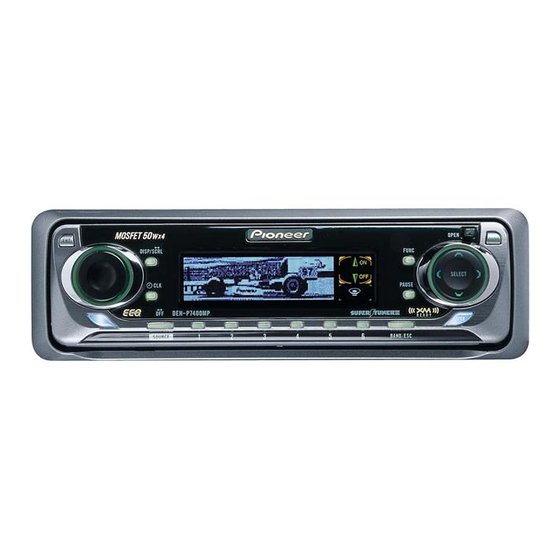
Pioneer DEH-P7400MP Service Manual
Multi-cd/dab control high power cd/mp3 player with rds tuner
Hide thumbs
Also See for DEH-P7400MP:
- Operation manual (112 pages) ,
- Installation manual (6 pages) ,
- Service manual (95 pages)
Table of Contents
Advertisement
Service
Manual
MULTI-CD/DAB CONTROL HIGH POWER CD/MP3 PLAYER WITH RDS TUNER
DEH-P7400MP
- This service manual should be used together with the following manual(s):
Model No.
Order No.
CX-3007
CRT2820
CONTENTS
1. SAFETY INFORMATION ............................................3
2. EXPLODED VIEWS AND PARTS LIST .......................4
4. PCB CONNECTION DIAGRAM ................................28
5. ELECTRICAL PARTS LIST ........................................36
6. ADJUSTMENT..........................................................42
For details, refer to "Important symbols for good services".
PIONEER CORPORATION
PIONEER ELECTRONICS (USA) INC.
PIONEER EUROPE NV
Haven 1087 Keetberglaan 1, 9120 Melsele, Belgium
PIONEER ELECTRONICS ASIACENTRE PTE.LTD. 253 Alexandra Road, #04-01, Singapore 159936
C PIONEER CORPORATION 2001
Mech. Module Remarks
S9MP3
CD Mech. Module:Circuit Description, Mech.Description, Disassembly
4-1, Meguro 1-Chome, Meguro-ku, Tokyo 153-8654, Japan
P.O.Box 1760, Long Beach, CA 90801-1760 U.S.A.
7. GENERAL INFORMATION .......................................51
7.1 DIAGNOSIS ........................................................51
7.1.1 DISASSEMBLY .........................................51
7.1.2
7.2 IC ........................................................................56
7.3 OPERATIONAL FLOW CHART ...........................68
7.4 CLEANING ..........................................................69
8. OPERATIONS AND SPECIFICATIONS.....................70
K-ZZD. DEC. 2001 Printed in Japan
ORDER NO.
CRT2784
XN/EW
.......55
Advertisement
Table of Contents

Related Manuals for Pioneer DEH-P7400MP


Summary of Contents for Pioneer DEH-P7400MP
- Page 1 PIONEER ELECTRONICS (USA) INC. P.O.Box 1760, Long Beach, CA 90801-1760 U.S.A. PIONEER EUROPE NV Haven 1087 Keetberglaan 1, 9120 Melsele, Belgium PIONEER ELECTRONICS ASIACENTRE PTE.LTD. 253 Alexandra Road, #04-01, Singapore 159936 C PIONEER CORPORATION 2001 K-ZZD. DEC. 2001 Printed in Japan...
- Page 2 DEH-P7400MP [ Important symbols for good services ] In this manual, the symbols shown-below indicate that adjustments, settings or cleaning should be made securely. When you find the procedures bearing any of the symbols, be sure to fulfill them: 1. Product safety You should conform to the regulations governing the product (safety, radio and noise, and other regulations), and should keep the safety during servicing by following the safety instructions described in this manual.
-
Page 3: Safety Information
DEH-P7400MP 1. SAFETY INFORMATION This service manual is intended for qualified service technicians; it is not meant for the casual do-it-yourselfer. Qualified technicians have the necessary test equipment and tools, and have been trained to properly and safely repair complex products such as those covered by this manual. -
Page 4: Exploded Views And Parts List
DEH-P7400MP 2. EXPLODED VIEWS AND PARTS LIST 2.1 PACKING... - Page 5 DEH-P7400MP NOTE: - Parts marked by “*” are generally unavailable because they are not in our Master Spare Parts List. - Screws adjacent to ∇ mark on the product are used for disassembly. - For the applying amount of lubricants or glue, follow the instructions in this manual.
- Page 6 DEH-P7400MP 2.2 EXTERIOR...
- Page 7 DEH-P7400MP - EXTERIOR SECTION PARTS LIST Mark No. Description Part No. Mark No. Description Part No. 1 Screw BMZ30P040FZK 51 Arm CNV6508 2 Screw BMZ30P100FMC 52 Panel Unit CWM7986 3 Screw BSZ26P060FMC 53 Socket(CN1850) CKS3550 4 Screw BSZ30P040FMC 54 Connector(CN1851)
- Page 8 DEH-P7400MP 2.3 CD MECHANISM MODULE GEM1040 GEM1035 GEM1035...
- Page 9 DEH-P7400MP - CD MECHANISM MODULE SECTION PARTS LIST Mark No. Description Part No. Mark No. Description Part No. 1 CD Core Unit(S9MP3) CWX2617 46 Gear CNV6320 2 Connector(CN901) CKS4186 47 Arm CNV6322 48 Arm CNV6323 3 Connector(CN101) CKS3486 4 Screw...
-
Page 10: Block Diagram And Schematic Diagram
DEH-P7400MP 3. BLOCK DIAGRAM AND SCHEMATIC DIAGRAM 3.1 BLOCK DIAGRAM TUNER AMP UNIT FM/AM TUNER UNIT Q153 Q151 Q155 FM/AM 1ST IF 10.7MHz MPXREF 41kHz CN401 AMRF T51 Q51 CF51 CF52 CF53 AMDET AMANT L ch IC 2 FM MPX... - Page 11 DEH-P7400MP RESET CN351 IC 961 S-80735ANDZI Q351 CN352-1 TMUTE Q352 FM/AM Q353 SYSTEM CONTROLLER IC 601(1/2) PD5702A CN352-2 VDD REGULATOR LDET Q911 NL2DT CN901 BACKUP SENSE FUSE BSENS BACK UP SDBW Q931 TUNPCE ASENS TUNPCK ACC SENSE Q932 TUNPCE2 ILL SENSE...
- Page 12 DEH-P7400MP 3.2 OVERALL CONNECTION DIAGRAM(GUIDE PAGE) Note: When ordering service parts, be sure to refer to “EXPLODED VIEWS AND PARTS LIST” or “ELECTRICAL PARTS LIST”. A-a A-b A-a A-b CD CORE UNIT(S9MP3) VD REGULATOR IP-BUS CN901 Large size IP-BUS:+2.2dBs SCH diagram Guide page CD:-0.2dBs...
- Page 13 DEH-P7400MP TUNER AMP UNIT LEVEL INDICATOR ELECTRONIC VOLUME, SOURCE SELECTOR MUTE FM:+5.84dBs AM:-2.66dBs IP-BUS:+8.54dBs CD:+9.14dBs REAR R CH MUTE REAR L CH PML009A L CH R CH FM: +6.6dBs AM: -1.9dBs FRONT IP-BUS: +7.3dBs L CH CD: +7.9dBs MUTE FRONT...
- Page 14 DEH-P7400MP...
- Page 15 DEH-P7400MP A-a B...
- Page 16 DEH-P7400MP...
- Page 17 DEH-P7400MP...
- Page 18 DEH-P7400MP 3.3 KEYBOARD UNIT CN1851 3.3V REGULATOR REMOTE CONTROL SENSOR VOLUME DISP/SCRL TEXT SFEQ ← BAND/ESC...
- Page 19 DEH-P7400MP KEYBOARD UNIT FONT ROM KEY CONTROL AND OEL CONTROL OEL UNIT MXS8017...
- Page 20 DEH-P7400MP 3.4 CD MECHANISM MODULE(GUIDE PAGE) CD CORE UNIT(S9MP3) D-RAM PICKUP UNIT(SERVICE) (P9MP3) SWITCHES: CD CORE UNIT(S9MP3) ..S901 : HOME SWITCH ON-OFF ..S902 : CLAMP SWITCH ON-OFF ..S903 : DSCSNS SWITCH ON-OFF ... S904 : 12EJ SWITCH ON-OFF ....
- Page 21 DEH-P7400MP SIGNAL LINE FOCUS SERVO LINE TRACKING SERVO LINE CARRIAGE SERVO LINE SPINDLE SERVO LINE & CN653...
- Page 22 DEH-P7400MP...
- Page 23 DEH-P7400MP...
- Page 24 DEH-P7400MP...
- Page 25 DEH-P7400MP...
- Page 26 DEH-P7400MP Note:1. The encircled numbers denote measuring points in the circuit diagram. 2. Reference voltage REFO1 : 1.65V - Waveforms 5 CH1:SIN 1 CH1:DSCSNS 5V/div. 1 CH1:DSCSNS 5V/div. 1V/div. 2 CH2:CLCONT 2 CH2:CLCONT 6 CH2:CIN 500mV/div. 5V/div. 5V/div. 2s/div. 500ms/div.
- Page 27 DEH-P7400MP 8 CH1:FIN 0 CH1:TE # CH1:RFAGC 1V/div. 500mV/div. 500mV/div. 200ms/div. 2ms/div. 0 CH2:TE ! CH2:FE # CH2:RFAGC 500mV/div. 500mV/div. 500µs/div. 500mV/div. 7 CH3:TIN 500mV/div. Focus Search 1Track Jump When "Tracking Open" Ref. : Ref. : Ref. : REFO REFO...
-
Page 28: Pcb Connection Diagram
DEH-P7400MP 4. PCB CONNECTION DIAGRAM 4.1 TUNER AMP UNIT TUNER AMP UNIT CORD ASSY CORD ASSY (OUTPUT,POWER (PREOUT) SUPPLY) NOTE FOR PCB DIAGRAMS 1. The parts mounted on this PCB include all necessary parts for several destination. For further information for... - Page 29 DEH-P7400MP SIDE A CORD ASSY (TEL) IC,Q PRE OUT RL RR 8 10 12 14 18 20 22 24 IP-BUS 9 11 13 17 19 21 23 25 ANTENNA JACK 12 14 11 13 FRONT CN1850 CN901...
- Page 30 DEH-P7400MP TUNER AMP UNIT IC,Q...
- Page 31 DEH-P7400MP SIDE B...
-
Page 32: Panel Unit
DEH-P7400MP 4.2 PANEL UNIT PANEL UNIT PANEL UNIT SIDE B SIDE A CN1901 CN801 EJECT... - Page 33 DEH-P7400MP 4.3 KEYBOARD UNIT SIDE A SIDE B KEYBOARD UNIT KEYBOARD UNIT ← CN1851 OEL UNIT OEL UNIT...
-
Page 34: Cd Mechanism Module
DEH-P7400MP 4.3 CD MECHANISM MODULE CD CORE UNIT(S9MP3) SIDE A 12EJ DSCSNS HOME REFO1... - Page 35 DEH-P7400MP CD CORE UNIT(S9MP3) SIDE B CLAMP R790...
-
Page 36: Electrical Parts List
DEH-P7400MP 5. ELECTRICAL PARTS LIST NOTES: - Parts whose parts numbers are omitted are subject to being not supplied. - The part numbers shown below indicate chip components. Chip Resistor RS1/_S___J,RS1/__S___J Chip Capacitor (except for CQS..) CKS.., CCS.., CSZS..=====Circuit Symbol and No.===Part Name Part No. - Page 37 DEH-P7400MP =====Circuit Symbol and No.===Part Name Part No. =====Circuit Symbol and No.===Part Name Part No. ------ ------------------------------------------ ------------------------- ------ ------------------------------------------ ------------------------- RS1/16S223J RS1/16S473J RS1/16S223J RS1/16S681J RS1/16S102J RS1/16S103J RS1/16S102J RS1/16S681J RS1/16S104J RS1/16S681J RS1/16S104J RS1/16S681J RS1/16S563J RS1/16S473J RS1/16S563J RS1/16S472J RS1/16S474J RS1/16S473J RS1/16S474J...
- Page 38 DEH-P7400MP =====Circuit Symbol and No.===Part Name Part No. =====Circuit Symbol and No.===Part Name Part No. ------ ------------------------------------------ ------------------------- ------ ------------------------------------------ ------------------------- RS1/16S222J CKSRYB123K25 RS1/16S222J CEJQ470M10 RS1/16S222J CKSRYB104K16 RS1/16S222J CEJQ100M16 RS1/16S222J CCSRCH100D50 RS1/16S473J CCSRCH100D50 RS1/16S104J CCSRCH100D50 RD1/4PU391J CCSRCH100D50 RS1/16S222J CKLSRB152K50 RS1/16S222J...
- Page 39 DEH-P7400MP =====Circuit Symbol and No.===Part Name Part No. =====Circuit Symbol and No.===Part Name Part No. ------ ------------------------------------------ ------------------------- ------ ------------------------------------------ ------------------------- CKSRYB471K50 1984 CL170UBX CKSRYB471K50 1993 CL170PGCD CKSRYB104K16 1996 CL170PGCD CEJQ220M6R3 1901 Inductor CTF1530 CCSRCH101J50 1902 Inductor CTF1530 CKSRYB102K50 1922...
- Page 40 DEH-P7400MP =====Circuit Symbol and No.===Part Name Part No. =====Circuit Symbol and No.===Part Name Part No. ------ ------------------------------------------ ------------------------- ------ ------------------------------------------ ------------------------- 1949 RS1/16S102J Transistor DTC323TK 1950 RS1/16S102J Transistor 2SB709A 1961 RS1/16S473J Transistor UN2111 1962 RS1/16S272J Diode 1SS355 1963 RS1/16S473J Diode...
- Page 41 DEH-P7400MP =====Circuit Symbol and No.===Part Name Part No. =====Circuit Symbol and No.===Part Name Part No. ------ ------------------------------------------ ------------------------- ------ ------------------------------------------ ------------------------- RS1/16SS822J CKSRYB102K50 RS1/16SS183J CKSSYB104K10 RS1/16SS822J CEV100M16 RS1/16SS0R0J CKSSYB471K50 RS1/16S101J CKSSYB104K10 RS1/16S101J CKSSYB104K10 RS1/16S223J CEV220M6R3 RS1/16S223J CKSSYB103K16 RS1/16SS103J CKSSYB103K16 RS1/16SS0R0J...
-
Page 42: Adjustment
DEH-P7400MP 6. ADJUSTMENT 6.1 OEL UNIT ADJUSTMENT Adjustment point KEYBOARD UNIT (SIDE B) CN1901 IC1901 VR1941 Digital Multi-Meter IC1902 <When the OEL Unit has been replaced> 1. Use VR1941 to adjust the resistance between TP1 and TP2 to 6.60kΩ. - Page 43 DEH-P7400MP 6.2 CD ADJUSTMENT 1) Precautions 2) Test Mode • This unit uses a single power supply (+3.3V) for the This mode is used for adjusting the CD mechanism regulator. The signal reference potential, therefore, is module of the device.
- Page 44 DEH-P7400MP - Flow Chart [4]+[6]+Reset [KEY] Test Mode In Contents Display [CD] or [SOURCE] Source On [BAND] RF AMP Power On Power On New Test Mode Gain switching (T. offset is adjusted) (T. offset is not adjusted) [BAND] Tracking Servo...
-
Page 45: Checking The Grating After Changing The Pickup Unit
DEH-P7400MP 6.3 CHECKING THE GRATING AFTER CHANGING THE PICKUP UNIT • Note : The grating angle of the PU unit cannot be adjusted after the PU unit is changed. The PU unit in the CD mecha- nism module is adjusted on the production line to match the CD mechanism module and is thus the best adjusted PU unit for the CD mechanism module. - Page 46 DEH-P7400MP Ech → Xch 20mV/div, AC Grating waveform Fch → Ych 20mV/div, AC 0° 30° 45° 60° 75° 90°...
-
Page 47: Cd Test Mode
DEH-P7400MP 6.4 CD TEST MODE - Error Messages If a CD is not operative or stopped during operation due to an error, the error mode is turned on and cause(s) of the error is indicated with a corresponding number. This arrangement is intended at reducing nonsense calls from the users and also for facilitating trouble analysis and repair work in servicing. - Page 48 DEH-P7400MP - New Test Mode S-CD plays the same way as before. If an error such as off focus, spindle unlocking, unreadable sub-code, or sound skipping occurs after setup, its cause and time occurred (in absolute time) are displayed. During setup, operational status of the control software is displayed.
- Page 49 DEH-P7400MP (4) Display of Operational Status during Setup Status No. Contents Protective action Focus search start Focus search timeout. Focus search 2 Focus search timeout. Focus search 3 Focus search timeout. Focus search 4 Focus search timeout. Focus search(Setup protection) Focus slips off.
- Page 50 DEH-P7400MP (5) Display Examples 1) During Setup 8-digit display, 6-digit display 4-digit display(Auto setting) 4-digit display(Manual setting) TNO. Min Sec TNO. Min Sec 11 11' 11" 11' 11" 2) During Operation (TOC read, TRK search, Play, FF and REV) The same as in the normal mode.
-
Page 51: General Information
DEH-P7400MP 7. GENERAL INFORMATION 7.1 DIAGNOSIS 7.1.1 DISASSEMBLY Removing the Case (not shown) 1. Remove the Case. CD Mechanism Module Removing the Grille Panel Assy (Fig.1) Remove the two screws and then remove the Grille Panel Assy. Removing the CD Mechanism Module (Fig.1) Remove the four screws and then remove the CD Mechanism Module. - Page 52 DEH-P7400MP - Removing the OEL Unit 1. Apply hot air to the cable pins for the anode terminal using a Anode terminal blower used for removing a flat-packaged IC or something like that. When all the pins are peeling off from the PCB, pinch the cable with a pair of tweezers and remove it slowly from the PCB.
- Page 53 DEH-P7400MP - How to hold the Mechanical Unit 1. Hold the top and bottom frame. 2. Do not squeeze top frame's front portion too tight, because it is fragile. Do not squeeze. - How to remove the Top and Bottom Frame Top Frame 1.
- Page 54 DEH-P7400MP - How to remove the CD Core Unit(S9MP3) 1. Give jumper-solder treatment to the Flexible Wire of Jumper-Solder the Pickup unit, then remove the wire from the CD Core Unit Connector. (S9MP3) 2. Remove all 4 points of solder-treatment on the Lead Wire.
-
Page 55: Connector Function Description
DEH-P7400MP 7.1.2 CONNECTOR FUNCTION DESCRIPTION SUB WOOFER NON-FADING OUTPUT FRONT OUTPUT 8 9 10 11 1 2 3 4 1. BUS+ 7. BL+ 1. GND 9. RL- ANTENNA 2. GND 8. ASENB 2. B.UP 10. FL- 3. GND 9. BR+ 3. - Page 56 DEH-P7400MP 7.2 IC PD5702A TSOP1840SB3V MSM51V4265EP-70TS PAL007A PD8088A BA5996FM PML009A PDH0044A PE5268A PD5706A UPD63760GJ PDH043A S-818A33AUC-BGN BA033SFP - Pin Functions (PD5702A) Pin No. Pin Name Function and Operation TUNPDO TUNER:Data output(PLL) TUNPCK TUNER:Clock output(PLL) EMUTE EVOL:Mute output (Not used) EVOL:Strobe output...
- Page 57 DEH-P7400MP Pin No. Pin Name Function and Operation TMUTE RDS:Mute output SDBW RDS:In case of NF, SD input Not used BRST PBUS:Reset output BRXEN PBUS:Comunication input/output BSRQ PBUS:Comunication request input 58-61 Not used Power supply input(Vcc) CSENSOUT CSENS output Power supply input(Vss)
- Page 58 DEH-P7400MP PAL007A sw_vcc amp_vcc sw_vcc stby 10 11 12 13 14 15 16 17 20 21 22 23 24 25 18 19 PML009A Isolator SEL_out_L SEL_out_R Treble Middle Bass Source Gain adjuster Primary PV_in_L Anti PV_in_R Loudness Volume Alias Volume...
- Page 59 DEH-P7400MP - Pin Functions (PD5706A) Pin No. Pin Name Function and Operation Not used OPEN Remote control reception input BYTE GND connection CNVSS GND connection 8, 9 Not used OPEN reset Pull up XOUT Crystal oscillating element connection pin VSS connection...
- Page 60 DEH-P7400MP *PD5706A *PD8088A *S-818A33AUC-BGN A15/A-1 :Data output/Address input A0-A19 :Address input D0-D19 :Data output byte/VPP :Mode select/Power supply ON/OFF byte/VPP :Chip enable input :Output enable input :Power supply :GND D15/A-1 ON/OFF VOUT *TSOP1840SB3V REGULATOR *PDH0044A NOISE AGC GAIN :Not used DET.
- Page 61 DEH-P7400MP - Pin Functions (UPD63760GJ) Pin No. Pin Name Function and Operation R.GND GND for DRAM I/F Input of reset AB12-8 Address bus 12-8 from the microcomputer 8-15 AD7-0 Address/data bus 7-0 to the microcomputer Chip selection ASTB Address strobe...
- Page 62 DEH-P7400MP Pin No. Pin Name Function and Operation cas) Output of DRAM Lower CAS cas! Output of DRAM Upper CAS Output of DRAM WE Output of DRAM OE 73-88 RDB0-15 Input/output of DRAM Data0-15 D.GND Ground for digital circuits 90-99...
- Page 63 DEH-P7400MP *UPD63760GJ *MSM51V4265EP-70TS 44 VSS 43 DQ16 42 DQ15 41 DQ14 40 DQ13 39 VSS A0-A8 :Address input 38 DQ12 ras : Row address strobe 37 DQ11 lcas : Lower column address strobe ucas : Upper column address strobe 36 DQ10...
- Page 64 DEH-P7400MP - Pin Functions(BA5996FM) Pin No. Pin Name Function and Operation Input pin for reference voltage OPIN2(+) Input pin for non-inverting input for CH2 preamplifier OPIN2(-) Input pin for inverting input for CH2 preamplifier OPOUT2 Output pin for CH2 preamplifier...
- Page 65 DEH-P7400MP - Pin Functions (PE5268A) Pin No. Pin Name Format Function and Operation FTXD For rewriting Flash EP-ROM (sending signals) Open Input of P-Bus serial data Output of P-Bus serial data bsck Input/output of P-Bus serial clock 6, 7 DFS1, 2...
- Page 66 DEH-P7400MP Pin No. Pin Name Format Function and Operation AVREF Input of reference voltage for A/D converter VDSENS Input of sensing short of VD power supply DSCSNS Input of sensing disc status TEMP Input of sensing information on temperature HOME...
- Page 67 DEH-P7400MP - FM/AM Tuner Unit FM/AM 1ST IF 10.7MHz MPXREF 41kHz AMRF T51 Q51 CF51 CF52 CF53 AMDET AMANT L ch IC 2 FM MPX R ch ANT ADJ COMP MIXER, IF AMP, DET. LDET FMANT RFGND FMRF CF202 IC 3...
-
Page 68: Operational Flow Chart
DEH-P7400MP 7.3 OPERATIONAL FLOW CHART Power ON VCC=5V Pin 16 BSENS Pin 73 BSENS=L ASENS Pin 74 ASENS=L DSENS Pin 41 DSENS=L ASENBO←H Pin 82 CSENS < < - CSENS 2V , 3V CSENS Pin 93 Last source returns. 2V<CSENS<3V CD and TAPE loading functions are available. -
Page 69: Cleaning
DEH-P7400MP 7.4 CLEANING Before shipping out the product, be sure to clean the following portions by using the prescribed cleaning tools: Portions to be cleaned Cleaning tools CD pickup lenses Cleaning liquid : GEM1004 Cleaning paper : GED-008... -
Page 70: Operations And Specifications
DEH-P7400MP 8. OPERATIONS AND SPECIFICATIONS 8.1 OPERATIONS HEAD UNIT TA button VOLUME OPEN button ENTERTAINMENT button FUNCTION button DISPLAY button TEXT button AUDIO button / / / buttons SELECT SFEQ button SOURCE button 1-6 buttons EQ button BAND/ESC button STEERING REMOTE CONTROL UNIT (CD-SR80) The steering remote control CD-SR80 is sold separately. - Page 71 DEH-P7400MP...
-
Page 72: Specifications
DEH-P7400MP 8.2 SPECIFICATIONS Tone controls: General (Bass) Power source ..... 14.4 V DC Frequency ..40/63/100/160 Hz (10.8 – 15.1 V allowable) Gain ....±12 dB Grounding system ..Negative type (Treble) Max. current consumption Frequency ..2.5 k/4 k/6.3 k/10 k Hz ........