Table of Contents
Advertisement
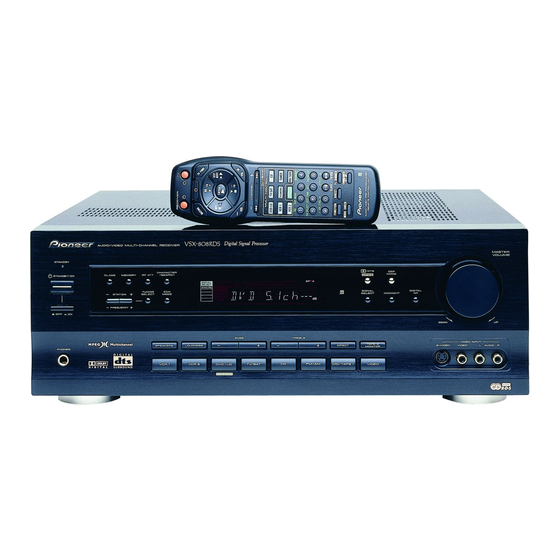
AUDIO/VIDEO MULTI-CHANNEL RECEIVER
VSX-808RDS
THIS MANUAL IS APPLICABLE TO THE FOLLOWING MODEL(S) AND TYPE(S).
Model
Type
VSX-808RDS
HYXJI
HYXJIGR
HVXJI
∗
: Alter the wiring of the Power-supply block at the primary winding of Power-transformer referring to the "Line Voltage Selection" described
in Service Manual.
CONTENTS
1. SAFETY INFORMATION ...................................... 2
2. EXPLODED VIEWS AND PARTS LIST ................ 3
3. SCHEMATIC DIAGRAM ....................................... 6
4. PCB CONNECTION DIAGRAM .......................... 26
5. PCB PARTS LIST ............................................... 39
6. ADJUSTMENT .................................................... 44
PIONEER ELECTRONIC CORPORATION
PIONEER ELECTRONICS SERVICE, INC. P.O. Box 1760, Long Beach, CA 90801-1760, U.S.A.
PIONEER ELECTRONIC (EUROPE) N.V. Haven 1087, Keetberglaan 1, 9120 Melsele, Belgium
PIONEER ELECTRONICS ASIACENTRE PTE. LTD. 253 Alexandra Road, #04-01, Singapore 159936
c
PIONEER ELECTRONIC CORPORATION 1999
AUDIO/VIDEO MUL TI-CHANNEL RECEIVER
ST ANDBY
CLASS
MEMORY RF A TT
ST ANDBY/ON
-
ST A TION
-
FREQUENCY
-
-
OFF
ON
PHONES
Power Requirement
AC220-230V
AC220-230V
AC230V
4-1, Meguro 1-Chome, Meguro-ku, Tokyo 153-8654, Japan
CHARACTER
/ DTS
DSP
/SEARCH
MPEG
MODE
TUNING
EON
+
SIGNAL
DIGIT AL
SELECT
MODE
SELECT
MIDNIGHT
NR
+
DOWN
BASS
TREBLE
-
+
-
+
T APE 2
VIDEO INPUT
SPEAKERS
LOUDNESS
DIRECT
MONIT OR
S-VIDEO
VIDEO
R
FM/AM
VCR 1
VCR 2
DVD/LD
TV/SA T
CD
MD/T APE 1
VIDEO
DVD 5.1CH
The voltage can be converted by the
following method.
∗
AC240V,
∗
AC240V,
∗
AC240V,
7. GENERAL INFORMATION ................................ 45
7.1 PARTS .......................................................... 45
7.1.1 IC ........................................................... 45
7.1.2 DISPLAY ................................................ 48
7.2 DISASSEMBLY ............................................ 50
7.3 BLOCK DIAGRAM ........................................ 52
7.4 REMOTE CONTROL UNIT .......................... 53
[CU-VSX140 (AXD7181)]
MASTER
VOLUME
UP
L
AUDIO R
ORDER NO.
EON
RRV2115
T - ZZK APR. 1999 Printed in Japan
Advertisement
Table of Contents

Related Manuals for Pioneer VSX-808RDS


Summary of Contents for Pioneer VSX-808RDS
-
Page 1: Table Of Contents
PIONEER ELECTRONIC CORPORATION 4-1, Meguro 1-Chome, Meguro-ku, Tokyo 153-8654, Japan PIONEER ELECTRONICS SERVICE, INC. P.O. Box 1760, Long Beach, CA 90801-1760, U.S.A. PIONEER ELECTRONIC (EUROPE) N.V. Haven 1087, Keetberglaan 1, 9120 Melsele, Belgium PIONEER ELECTRONICS ASIACENTRE PTE. LTD. 253 Alexandra Road, #04-01, Singapore 159936 PIONEER ELECTRONIC CORPORATION 1999 T –... -
Page 2: Safety Information
The use of a substitute replacement component which does Leakage 0.5mA current Device not have the same safety characteristics as the PIONEER tester under recommended replacement one, shown in the parts list in test this Service Manual, may create shock, fire, or other hazards. -
Page 3: Exploded Views And Parts List
Operating Instructions See Contrast table (2) Operating Instructions See Contrast table (2) 11(2/2) (2) CONTRAST TABLE VSX-808RDS/HYXJI, HYXJIGR and HVXJI are constructed the same except for the following : Part No. Mark No. Symbol and Description Remarks HYXJI Type HYXJIGR Type... - Page 4 VSX-808RDS 2.2 EXTERIOR Except HVXJI Type (HVXJI Type Only) ∗ ∗ Note Torque is 12 kg • cm –0 ∗ 19 54 Accessories of Front Panel 608 59 53 (No. 47) HVXJI Type Only...
- Page 5 AMR2533 Cord Clamper RNH-184 Card Spacer DEC1770 Binder RNE1277 (2) CONTRAST TABLE VSX-808RDS/HYXJI, HYXJIGR and HVXJI are constructed the same except for the following : Part No. Mark No. Symbol and Description Remarks HYXJI Type HYXJIGR Type HVXJI Type AC Power Cord...
-
Page 6: Schematic Diagram
VSX-808RDS 3. SCHEMATIC DIAGRAM 3.1 OVERALL WIRING CONNECTION DIAGRAM FM/AM TUNER 1/3- UNIT FRONT VIDEO DOLBY DIGITAL (AXX7048) ASSY ASSY CN9551 (AWX7241) (AWX7374) 1/2, INPUT ASSY (AWX7210) SVIDEO ASSY VIDEO ASSY (AWX7378) (AWX7236) - Page 7 VSX-808RDS Note : When ordering service parts, be sure to refer to "EXPLODED VIEWS and PARTS LIST" or "PCB PARTS LIST". POWER SW HEADPHONE MECH SW ASSY ASSY ASSY (AWX7222) (AWX7230) FRONT ASSY (AWX7247) (AWX7217) TRANS 1 ASSY (AWX7287) POWER TRANSFORMER (T1)
- Page 8 VSX-808RDS 3.2 INPUT ASSY (1/2) CN602 INPUT ASSY(1/2) (AWX7210) • FUNCTION BLOCK TO FM/AM TUNER UNIT CN202...
- Page 9 VSX-808RDS L ch : AUDIO SIGNAL ROUTE C ch : AUDIO SIGNAL ROUTE (CENTER) FL ch : AUDIO SIGNAL ROUTE (FRONT) CN9801 CN554 ACH7112 3300/35 ACH7113 2200/35 CN507 CN9802...
- Page 10 VSX-808RDS 3.3 INPUT ASSY (2/2) INPUT ASSY(2/2) (AWX7210) • E. VOL BLOCK IC301 LC7535M (LC7536M) 120p IC303 LC7535M (LC7536M)
- Page 11 VSX-808RDS FL ch : AUDIO SIGNAL ROUTE (FRONT) 120p IC302 LC7535M (LC7536M) 120p...
- Page 12 VSX-808RDS 3.4 FRONT and POWER SW ASSYS CN111 REMOTE RECEIVER UNIT MASTER VOLUME POWER SW ASSY (AWX7222) CN9551...
- Page 13 VSX-808RDS CN401 FRONT ASSY (AWX7217) FRONT ASSY S201 : SIGNAL SELECT S202 : MIDNIGHT S203 : DIGITAL NR S205 : – BASS S206 : + S207 : – TREBLE S208 : + S209 : SPEAKERS S210 : LOUDNESS S211 : DIRECT...
- Page 14 VSX-808RDS 3.5 AMP (1/2), F.SP.CONNECT, R.C.SP.CONNECT, FRONT LARGE and REAR SP ASSYS 4.7/50 C439 220p /500 4.7/50 C1439 10000p R1456 C1442 4.7/50 220p /500 C1441 220p /500 39p 39p 4.7/50 C442 220p /500 4.7/50 C1438 330p AMP ASSY(1/2) (AWX7226) JA413...
- Page 15 VSX-808RDS FL ch : AUDIO SIGNAL ROUTE (FRONT) F.SP. CONNECT ASSY 0.22 RETURN (AWX7285) 0.22 FRONT LARGE ASSY (AWX7245) 0.22 0.22 0.22 0.22 AKE7026 C443 220p/500 C444 220p/500 RETURN JA653 AKB7111 0.22 0.22 AKE7042 REAR SP ASSY (AWX7251) 0.22 0.22 R.C.SP.
- Page 16 VSX-808RDS 3.6 AMP (2/2), HEADPHONE, TRANS 2, TRANS 1, BARRIER, FET and MECH SW ASSYS CN203 AMP ASSY(2/2) (AWX7226) +42.4 –42.4 CN376 : AUDIO SIGNAL ROUTE (HEAD PHONE) ATT7037 HEADPHONE ASSY (AWX7230) VNF-091...
-
Page 17: Trans 1 Assy
VSX-808RDS CAUTION : FOR CONTINUED PROTECTION AGAINST RISK OF FIRE, FET ASSY (AWX7228) REPLACE ONLY WITH SAME TYPE NO. ICP-N70, MFD BY ROHM CO., LTD. FOR IC353. CAUTION : FOR CONTINUED PROTECTION AGAINST RISK OF FIRE, REPLACE ONLY WITH SAME TYPE NO. 491005, MFD BY LITTELFUSE INK. - Page 18 VSX-808RDS 3.7 VIDEO, SVIDEO and FRONT VIDEO ASSYS VIDEO ASSY (AWX7236) UPC4570C UPC4570C CN110 UPC4570C UPC4570C...
-
Page 19: Svideo Assy
VSX-808RDS : S-VIDEO Y-SIGNAL ROUTE SVIDEO ASSY : S-VIDEO C-SIGNAL ROUTE (AWX7378) : S-VIDEO C-DC ROUTE CN602 PCB BINDER CN601 FRONT VIDEO ASSY (AWX7241) PCB BINDER Y20 ADX7248... - Page 20 VSX-808RDS 3.8 DOLBY DIGITAL ASSY (1/3) C9121 (R9103)
- Page 21 VSX-808RDS DOLBY DIGITAL ASSY(1/3) (AWX7374) • INPUT, CODEC & CONTROL BLOCK C9506 (R9521) 7.7MHz CN201 CN113...
- Page 22 VSX-808RDS 3.9 DOLBY DIGITAL ASSY (2/3)
- Page 23 VSX-808RDS DOLBY DIGITAL ASSY(2/3) (AWX7374) • DSP & MEMORY BLOCK...
- Page 24 VSX-808RDS 3.10 DOLBY DIGITAL ASSY (3/3) UPC4570G2 UPC4570G2 UPC4570G2 UPC4570G2 UPC4570G2 UPC4570G2...
- Page 25 VSX-808RDS DOLBY DIGITAL ASSY(3/3) (AWX7374) • OUTPUT FILTER & MUTE BLOCK UPC4570G2 UPC4570G2 UPC4570G2 UPC4570G2 UPC4570G2 UPC4570G2 UPC4570G2 UPC4570G2 UPC4570G2 UPC4570G2...
-
Page 26: Pcb Connection Diagram
VSX-808RDS 4. PCB CONNECTION DIAGRAM 4.1 INPUT and FRONT VIDEO ASSYS NOTE FOR PCB DIAGRAMS : 1. Part numbers in PCB diagrams match those in the schematic 3. The parts mounted on this PCB include all necessary parts for diagrams. - Page 27 VSX-808RDS FM/AM TUNER UNIT CN202 CN554 (ANP7273-A) CN9802 CN9801 CN507 IC102 Q104-Q107 IC101 IC103 Q101-Q103 SIDE A...
- Page 28 VSX-808RDS INPUT ASSY IC109 IC307-IC309 SIDE B...
- Page 29 VSX-808RDS (ANP7273-A) 07-IC309 IC301-IC303 IC304-IC306 IC310 SIDE B...
- Page 30 VSX-808RDS 4.2 FRONT and POWER SW ASSYS CN401 POWER Q202 Q205 Q204 Q282 Q281 IC281 Q203 Q201 SW ASSY IC201...
- Page 31 VSX-808RDS CN111 (ANP7273-A) SIDE A FRONT ASSY CN9551 Q201 Q207 Q206 Q283 FRONT ASSY SIDE B (ANP7273-A)
-
Page 32: Amp Assy
VSX-808RDS 4.3 AMP, HEADPHONE, FET and MECH SW ASSYS (ANP7274-A) (ANP7268-B) MECH SW ASSY FET ASSY HEADPHONE ASSY Q1452 Q1451 SIDE A (ANP7274-A) CN203 AMP ASSY CN112 Q403 Q407 Q404 Q1404 Q1405 IC405 Q401 Q405 Q406 Q402 IC401 Q408 Q1402... - Page 33 VSX-808RDS NEUTRAL AC IN LIVE (ANP7274-A) Q454 IC701 Q701 Q453 Q456 Q458 Q452 IC404 Q711-Q714 IC403 Q1403 Q1401 Q451 Q457 IC402 Q1433 Q1434 Q455...
- Page 34 VSX-808RDS 4.4 F.SP.CONNECT, R.C.SP.CONNECT, FRONT LARGE and REAR SP ASSYS FRONT LARGE ASSY Q628 Q626 Q627 Q631 Q629 Q630 (ANP7268-B) F.SP. CONNECT ASSY (ANP7274-A) Q652 Q651 (ANP7274-A) R.C.SP. CONNECT ASSY REAR SP REAR SP ASSY ASSY (ANP7273-A) SIDE B SIDE A...
- Page 35 VSX-808RDS 4.5 TRANS 2, TRANS 1 and BARRIER ASSYS BARRIER ASSY (ANP7274-A) TRANS 2 ASSY CN115 (ANP7274-A) IC351 IC353 POWER TRANSFORMER (T1) Line Voltage Selection Line Voltage can be changed by the following modification: TRANS 1 1. Disconnect the AC power cord.
-
Page 36: Dolby Digital
VSX-808RDS 4.6 DOLBY DIGITAL ASSY IC9391 CN201 IC9374 IC9501 Q9609 Q9608 IC9373 Q9607 CN113 Q9610 IC9372 Q9606 IC9604 Q9605 IC9371 Q9604 IC9603 IC9705 Q9603 Q9602 Q9601 IC9602 IC9361 IC9321 CN108 IC9601 IC9311 IC9451 IC9702 IC9701 IC9401 IC9704 IC9703 Q9401 Q9203 Q9204... - Page 37 VSX-808RDS DOLBY DIGITAL ASSY IC9151 IC9101 SIDE B (ANP7297-B)
-
Page 38: Video Assy
VSX-808RDS 4.7 VIDEO and SVIDEO ASSYS IC501 Q501-Q505 Q506 IC502 IC503 VIDEO ASSY (ANP7274-A) CN110 SVIDEO ASSY Q557 Q556 Q551 Q552 IC553 IC551 IC552 Q554 Q553 CN602 (ANP7268-B) CN109 SIDE A... -
Page 39: Pcb Parts List
VSX-808RDS Mark No. Description Part No. Mark No. Description Part No. 5. PCB PARTS LIST • NOTES: Parts marked by "NSP" are generally unavailable because they are not in our Master Spare Parts List. • mark found on some component parts indicates the importance of the safety factor of the part. - Page 40 VSX-808RDS Mark No. Description Part No. Mark No. Description Part No. CN112 52147-1410 V201 FL TUBE AAV7062 14P JUMPER CONNECTOR CN104 6P PIN JACK AKB7015 X201 CERAMIC RESONATOR ASS1055 JA101–JA103 6P PIN JACK AKB7113 (7.7MHz) CN105 KR CONNECTOR B5B-PH-K-S X281...
- Page 41 VSX-808RDS Mark No. Description Part No. Mark No. Description Part No. C1441, C439, C442–C444 CCCSL221K2H F.SP.CONNECT ASSY C1420, C1421 CCCSL390J50 C437, C438, C479, C480 CCCSL470J50 OTHERS C1403, C1404, C405, C406 CEANP2R2M2A 13P CABLE HOLDER 51048-1300 C455, C456 CEANP2R2M2A C1415, C423, C424, C473, C474...
-
Page 42: Headphone Assy
VSX-808RDS Mark No. Description Part No. Mark No. Description Part No. OTHERS FET ASSY JA653 1P PIN JACK AKB7111 SEMICONDUCTORS CN652 SPEAKER TERMINAL 6P AKE7042 CN651 12P PLUG AKM7007 Q1452 IRF540A Q1451 IRF9540A RESISTORS HEADPHONE ASSY R1451, R1452 RD1/4PMF101J CAPACITORS... - Page 43 VSX-808RDS Mark No. Description Part No. Mark No. Description Part No. IC9391 PQ20WZ51 SVIDEO ASSY IC9151 TC74ACT151F IC9101 TC74HCU04AF SEMICONDUCTORS IC9311 TC74VHCT244AFT IC551, IC552 NJM2296D IC9451 TC7SH08FU IC553 TC4051BP Q554 2SA1515 IC9361 TC7WU04F Q551 2SA933S IC9601 TC9164AF Q552 2SC1740S IC9602–IC9604, IC9701–IC9705...
-
Page 44: Adjustment
VSX-808RDS Mark No. Description Part No. Mark No. Description Part No. 6. ADJUSTMENT C9203, C9204, C9603, C9604 CEWAR4R7M50 C9615, C9616, C9627, C9628 CEWAR4R7M50 There is no information to be shown in this chapter. C9103 CKSQYB102K50 C9101, C9107, C9153, C9313, C9322 CKSQYB103K50... -
Page 45: General Information
VSX-808RDS 7. GENERAL INFORMATION 7.1 PARTS 7.1.1 IC • The information shown in the list is basic information and may not correspond exactly to that shown in the schematic diagrams. PDG252A (FRONT ASSY : IC201) • System Control Microcomputer •... - Page 46 VSX-808RDS • Pin Function Pin Name Pin Function Active Grid output 2 Grid output 1 − Connect to VDD ACIN AC pulse input RDS_DT Serial control data signal for RDS communication RDS_CK Serial control clock signal for RDS communication (used for external interrupt)
- Page 47 VSX-808RDS Pin Name Pin Function Active SVIDEO1 SVIDEO2 TC4051 control (S terminal control) SVIDEO3 TMUTE Tuner mute VMUTE Video mute Not used Open LC4966 Input switch the DVD 6ch ST_9174 Strobe signal for communication with TC9174 Not used Open Not used...
-
Page 48: Display
VSX-808RDS 7.1.2 DISPLAY AAV7062 (FRONT ASSY : V201) • FL Indicator Tube • Pin Assignment • Pin Connection • Grid Assignment... - Page 49 VSX-808RDS • Anode Connection...
-
Page 50: Disassembly
VSX-808RDS 7.2 DISASSEMBLY Remove the Bonnet. (seven screws) Release three binders ( ) from the Power Transformer (T1). Remove all screws which fixing the Chassis. Power Transformer (T1) Heat Sink • INPUT Assy (eight screws , Card Spacer ×4 • DSP Shield (screw •... - Page 51 VSX-808RDS Open the Chassis and Rear Panel It can be disgnosed under this condition. Show the principal PCB Assemblies in the illustration. INPUT Assy (Side B) AMP Assy (Side B) Chassis Rear Panel Rear View Chassis DOLBY DIGITAL Assy Front Panel...
-
Page 52: Block Diagram
VSX-808RDS 7.3 BLOCK DIAGRAM TAPE2 IN TAPE2 OUT... -
Page 53: Remote Control Unit
VSX-808RDS 7.4 REMOTE CONTROL UNIT [CU-VSX140 (AXD7181)] 7.4.1 Exploded Views and Parts List • NOTES: Parts marked by "NSP" are generally unavailable because they are not in our Master Spare Parts List. • mark found on some component parts indicates the importance of the safety factor of the part. - Page 54 VSX-808RDS 7.4.2 Schematic Diagram Note : When ordering service parts, be sure to refer to "EXPLODED VIEWS and PARTS LIST" or "PCB PARTS LIST".
- Page 55 VSX-808RDS 7.4.3 PCB Diagram SIDE A SIDE B...
- Page 56 VSX-808RDS 7.4.4 PCB Parts List NOTES: ¶Parts marked by "NSP" are generally unavailable because they are not in our Master Spare Parts List. ¶The mark found on some component parts indicates the importance of the safety factor of the part.
-
Page 57: Panel Facilities And Specifications
VSX-808RDS 8. PANEL FACILITIES AND SPECIFICATIONS 8.1 PANEL FACILITIES Front Section 4 5 6 789 0 - = @ # $ % ^ & * AUDIO/VIDEO MUL TI-CHANNEL RECEIVER MASTER VOLUME ST ANDBY CHARACTER / DTS CLASS MEMORY RF A TT... -
Page 58: Master Volume
VSX-808RDS % SIGNAL SELECT button Use to select input signals for the digital components. First press DVD/LD, TV/SAT, MD/TAPE 1, CD or VCR 1 (+, Function buttons) to select the component, then press SIGNAL SELECT repeatedly to select one of the following: ANALOG : Selects the analog (R and L) audio signals. -
Page 59: Overload Indicator
VSX-808RDS Display 3 4 5 5-D THEATER TAPE2 DIRECT MPEG SIGNAL MONO MIDNIGHT LOUDNESS STEREO TUNED SELECT ANALOG PRO LOGIC DIGITAL DIGITAL RDS RF ATT AC-3 MPEG & 1 SIGNAL SELECT indicators 0 DIRECT indicator Light to indicate the type of input signal selected for the Lights when direct playback is on (refer to “Front Panel”,... -
Page 60: Remote Control Unit
VSX-808RDS Remote Control Unit 6 MULTI CONTROL buttons These pages describe the buttons on the remote control used to operate the receiver. Use these buttons to select the remote operation mode. For example, pressing TUNER sets the remote to operate the tuner functions. -
Page 61: Audio Components Connections
VSX-808RDS Audio Components Connections Be sure to switch power to standby and remove the power cord from the wall outlet when you make or change connections. Connect your audio components as shown below. FRONT SPEAKERS ANTENNA DIGITAL IN PCM/ UNBAL... -
Page 62: Specifications
VSX-808RDS 8.2 SPECIFICATIONS Amplifier Section FM Tuner Section Frequency Range ........87.5 MHz to 108 MHz Continuous average power output of 80 watts* Usable Sensitivity ..... Mono: 15.2 dBf, IHF (1.5 µV/75 Ω) per channel, min., at 8 ohms, from 20 Hz to 50 dB Quieting Sensitivity ........