Table of Contents
Advertisement
Quick Links
Advertisement
Table of Contents

Related Manuals for Mitsubishi Electric ME96NSR


Summary of Contents for Mitsubishi Electric ME96NSR
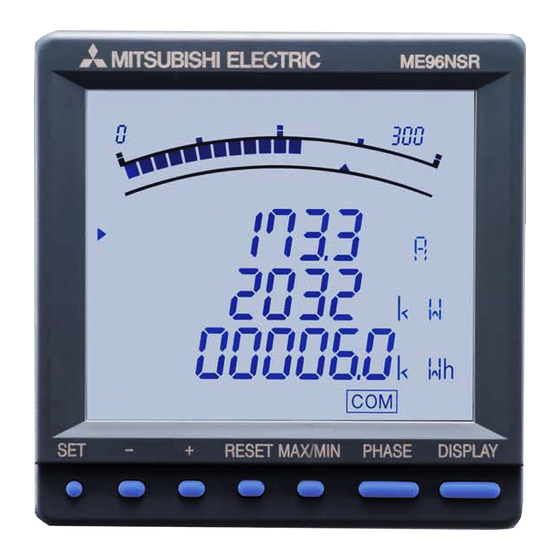
- Page 1 MITSUBISHI ELECTRONIC MULTI-MEASURING INSTRUMENT MODEL ME96NSR...
- Page 2 MITSUBISHI Electronic Multi-Measuring Instrument NS Series features high performance and crystal clear display. With simple operating functions, NS Series is the best support your measuring and moni- toring systems. Upper/lower limit monitoring up to 4 items Harmonics monitoring Measures import/export active energy 4 items displayable Backlight automatic off function Output functions for 7 items...
- Page 3 • Digital Input 4 points (24VDC) Circuit Breaker Status Signal etc Analog Pulse Transimission System (ME96NSR, Optional Plug-in Module ME-4201-NS96) ● Can remotely monitor A, DA, V, W, var, VA, PF, Hz, Harmonics Current RMS Value, and Harmonics Voltage RMS Value at 4 to 20mA output. (Max. of 4 outputs) ●...
- Page 4 Maximum of four displays can be set. < Functions Available > ■ Keep the display unchanged. Set only ■ Keep the display unchanged even when DISPLAY button is pressed. one display ■ Use ME96NSR instead of electric energy meter by displaying electric power.
- Page 5 ● Bar Graph Each measuring items can be displayed by a bar graph. With bar graph display, one can grasp the rated value and percentage against the alarm value instantly. Bar Graph Fixed Display Measuring items displayed by bar graph can be fixed. shows that display is fixed.
-
Page 6: Measuring Functions
Measuring Functions ● Accurate Measurement by Our Own ASIC Our own ASIC allows for accurate measurements. (For details on measurement accuracy, please refer to “Specifications” on page 26.) ● Harmonics Measurement Measuring of harmonics current, harmonics voltage is possible. This device can also be used for harmonics monitoring. <... - Page 7 Monitoring of Upper/Lower Limit ● Monitoring of Upper/Lower Limit (Max. 4 points) There is an output of upper/lower limit alarm when plug-in optional module ME-4201-NS96 is mounted. (Since contact output is 1 point, it becomes OR output set in upper/lower limit alarm item) ■...
- Page 8 Functions of LCD LEAD status They show direction of Power Factor or Reactive Power on bar graph. LAG status They show the type of counting of Reactive Energy on Reactive Energy Display. Scale of the bar graph They show the scales of the bar graph. Outside range Measurement value is outside range of scale of the bar graph.
- Page 9 Settings (Continued) ● Setting Procedure Display the setting screen with , and setup the items with – Settings can be registered for each setup menu number. Display the [End] screen and register with ■ Set-up Menu 1 (Basic Set-up) In this set-up menu 1, set-up the basic contents as following for correct measurement . In the operation mode, press simultaneously for 2 seconds or more, and the following operation becomes available.
- Page 10 Set the set-up menu number to “2”. ① Set the “CC-Link” or “ModBus” as the – communication method. Set-up menu This display appears only if the type ME96NSR-MB has the type ME-0040C-NS96 option module. DISPLAY SET – CC-Link ① Communication method ModBus ②...
- Page 11 ■ Set-up Menu 4 (Set-up of Various Measurement Display, Special Type Display) In the operation mode, press simultaneously for 2 seconds or more, and the following operation becomes available. RESET Set the set-up menu number to “4”. – Set-up menu DISPLAY SET ①...
- Page 12 Settings (Continued) ■ Set-up Menu 5 (Alarm Set-up) This sets the upper and lower limit alarm. The upper and lower limit set value mark “ (blinking)” is displayed on the bar graph. From the display items, four items can be set. In the operation mode, press simultaneously for 2 seconds or more, and the following operation becomes available.
- Page 13 ■ Set-up Menu 6 (Analog Output Set-up) In the operation mode, press simultaneously for 2 seconds or more, and the following operation becomes available. RESET The set-up screen can be displayed for measurement items that are not selected in display pattern. When the ME-4201-NS96 type optional plug-in module is not installed, this menu cannot be set.
- Page 14 Settings (Continued) ■ Set-up Menu 7 (Pulse Output Set-up) In the operation mode, press simultaneously for 2 seconds or more, and the following operation becomes available. RESET When the ME-4201-NS96 optional plug-in module is not installed, this menu cannot be set. ①...
- Page 15 ■ Simplified Set-up Contents List <Setting page: P-1> <Setting page: P-2> Phase wire Display pattern Using VT Direct voltage /direct input 00:P00 11:P11 [3P4W] 1:3P3W (2CT) 1:110V/63.5V 2:3P3W (3CT) 01:P01 12:P12 0:direct input 02:P02 13:P13 2:173V/100V 3:3P4W 1:using VT 3:190V/110V 03:P03 Communication ModBus...
- Page 16 04: 40s 09: 4min 14: 9min 19: 30min Set the communication method. This is set only if the type of ME96NSR-MB has the (Page change of set-up display) CC-Link optional plug-in module. In case of the – other combination, this content cannot be set.
- Page 17 Test Function ● Alarm Output Test When the ME-4201-NS96 optional plug-in module is installed, simulated signal output to test the alarm output circuit can be put out. The following operation becomes possible when you turn on the power supply while pressing at the state of power failure.
- Page 18 Test Function (Continued) ● Pulse Output Test When the ME-4201-NS96 optional plug-in module is installed, simulated signal output to test the pulse output circuit can be put out. The following operation becomes possible when you turn on the power supply while pressing at the state of power failure.
- Page 19 Operation ● Display Change By pressing DISPLAY , the measurement display switches over. Display change example (Display pattern: P01, Phase wire: Three phase 4 wire) Note 1: When the display is changed by pressing DISPLAY , the following display is displayed just for a few seconds. DISPLAY DISPLAY DISPLAY...
- Page 20 Operation (Continued) ● Maximum Value and Minimum Value Display The maximum values and the minimum values can be displayed. ■ Display of maximum value and minimum value When MAX/MIN is pressed, the display changes into maximum value and minimum value display. And when MAX/MIN is pressed, the display changes back to the present value display.
- Page 21 ● Generation and Cancel of Upper/Lower Limit Alarm When the value exceeds the upper or lower limit setting value set in advance, the display blinks and alarm can be output. (No alarm output when all of the input voltage/input current is zero) ■...
- Page 22 Operation (Continued) ● Harmonics Display Harmonic RMS value, distortion ratio, and content rate can be displayed. ■ Measuring Items Voltage Current (other than phase N) Current (phase N) Degree Distortion Distortion Distortion Distortion value value ratio ratio value ratio value ratio Harmonic total 11th...
- Page 23 ● Expanded Counting Display Measured value display and enlarged 3 digital figures display of active energy and reactive energy can be displayed. ■ Display of Active Energy and Reactive Energy Display Active energy and reactive energy are displayed on the lower stage. Total load [kW] Digital display Unit (k/M)
- Page 24 Operation (Continued) ● Display Patten Contents When the display elements are set in the set-up menu 1 and the set-up menu 4, by pressing DISPLAY , the display transits from No.1 in the order shown in the following table. Three phase 4-wire Screen set on display pattern Additional screen (displays when Set-up Menu 4 is set) Display...
- Page 25 Dimensions Option cover Optional Plug-in Module 95.8 (COVER) 88.8 25.2 81.2 46.8 17.1 91.6 (PANEL CUT) (With the optional plug-in module) Mounting 1 Dimensions of Panel 2 View Angle The panel hole dimensions are shown below. The contrast of the display changes at view angles. It can be attached to a panel with thickness of 1.6 to 4.0mm.
- Page 26 M The wires are connected correctly. M There is no mistake in wiring. Wiring Diagram Three phase 4-wire type : Example of ME96NSR (with VT) Three phase 4-wire type : Example of ME96NSR-MB (for direct input) RS485 T– (ModBus) RS485 (ModBus) ➀...
- Page 27 And use the shielded cables or twisted pair cables so that it is not affected noise, serge, and induction. Also, the wiring cables should be as short as possible. 3. In case of ME96NSR-MB with ME-4201-NS96, the ModBus interface and the analog outputs do not have the insulation between them. Optional Plug-in Module : ME-0040C-NS96...
-
Page 28: Specifications
Specifications Type ME96NSR, ME96NSR-MB Phase wire Three phase 4-wire Three phase 3-wire Current 5AAC/1AAC 5AAC/1AAC Rating Voltage max 277V/480VAC 110VAC, 220VAC Frequency 50-60Hz 50-60Hz Current (A) , Aavg , Aavg Current Demand (DA) , DA , DA , DA , DAavg... - Page 29 ● Twist Pair Cable Specifications Part of recommended cables of twist pair cables to be used in CC-Link are introduced below. As for details, refer to “Mitsubishi Electric Open Field Network CC-Link”. CC-Link performance is not guaranteed with other than the recommended cables.
- Page 30 Three-phase Automatic Power Factor Adjustment Device This device automatically controls power condenser input and adjusts power factor. Power loss and voltage rise can be prevented by using this device. ● Features • Lineup of 6-Circuit and 12-Circuit Control Types Only one device is needed where many condensers are needed in 12-circuit control such as large facility or low-voltage control.
- Page 31 (Always read these instructions before using this equipment) For personnel and product safety please read the contents of these operating instructions carefully before using. Please save this manual to make it accessible when required and always forward it to the end user. Indicates that incorrect handling may cause hazardous conditions.
- Page 32 EDISON ELECTRIC INTEGRATED, Philippines +63-(0)2-643-8691 Quezon City, Metro Manila. Philippines. INC. 307 Alexandra Road #05-01/02 Singapore MITSUBISHI ELECTRIC ASIA PTE LTD. +65-6473-2308 Mitsubishi Electric Building Singapore 159943 South Africa Circuit Breaker Industries LTD. Private Bag 2016. Isando 1600, Johannesburg, South Africa +27-11-928-2000 6F, NO.