Advertisement
Available languages
Available languages
Quick Links
Installation Instructions
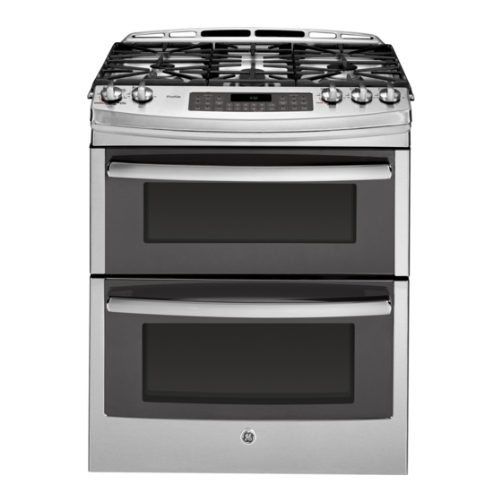
30" Electric Slide-In Ranges
Questions?
Call 1.800.561.3344 or visit www.GEAppliances.ca
BEFORE YOU BEGIN
Read these instructions completely and carefully.
•
IMPORTANT—
Save these instructions for local inspector's use.
•
IMPORTANT—
Observe all governing codes and ordinances.
• Note to Installer – Be sure to leave these instructions with Consumer.
• Note to Consumer – Keep these instructions for future reference.
• Skill level – Installation of this appliance requires basic mechanical
skills and advanced electrical skills.
• Proper installation is the responsibility of the installer.
• Product failure due to improper installation is not covered under warranty.
WARNING:
connected by means of the supplied cord and plug. If your kitchen does not
have a receptacle, you must have one installed by a licensed electrician.
FOR YOUR SAFETY:
WARNING
power off at service panel and lock the service disconnecting means to
prevent power from being switched on accidentally. When the service
disconnecting means cannot be locked, securely fasten a prominent
warning device, such as a tag, to the service panel.
TOOLS YOU WILL NEED
Drill with 1/8" Bit
Level
Safety Glasses
Tape Measure
Adjustable Wrench
1
REMOVE PACKAGING MATERIALS
Failure to remove packaging materials could result in damage to the
appliance. Remove all packing parts from oven, racks, heating elements
and drawer. Also, remove protective film and labels on the door, cooktop
(do not remove side protection on glass cooktops) and backguard.
Do not remove protective channel from sides of glass cooktop, if applicable,
until later in installation.
NOTE: Cut the orange shipping ties from the power cord, being careful not
to damage the cord.
2
ALTERNATE INSTALLATION/
CONSTRUCTION KITS
Description:
Backguard Kit: Adds a decorative backguard to the rear of the range. This kit can only
be used when the opening in the countertop is 63.5 cm (25") deep.
Maintop Filler Kit: Adds a filler strip to the rear of the range. This kit can only be used
when the opening in the countertop is 63.5 cm (25") deep. This kit cannot be used
with a backguard kit.
Body Side Kit: Contains a color-matched side panel which can be used to create
a finished appearance on either side of the range.
Lower Trim Kit: Contains a color-matched toe kick and extra-long leveling legs.
Designed to be used when the range needs to be raised higher than 92.7 cm (36-1/2").
To order accessory kits, call 1.800.661.1616, or visit www.GEAppliances.ca.
31-10674
11-08
JR
This appliance must be properly
If you did not receive an anti-tip
bracket with your purchase,
call 1.800.561.3344 to receive
one at no cost. For installation
instructions of the bracket,
visit www.GEAppliances.ca.
—
Before beginning the installation, switch
Pliers
1/4" Nut Driver
3
PREPARE THE OPENING
If the countertop area is not flat, excess tension may be applied to the glass
cooktop causing breakage and voiding the warranty. Make sure the wall
covering, countertop, flooring and cabinets around the range can withstand
the heat (up to 93˚C [200˚F]) generated by the range.
A. Allow 76.2 cm (30") minimum clearance between surface units and bottom
of unprotected wood or metal cabinet, or allow a 61 cm (24") minimum
when bottom of wood or metal cabinet is protected by no less then 6.3 mm
(1/4") thick flame retardant millboard covered with no less than No. 28 MSG
sheet metal .38 mm (.015") thick, .38 mm (.015") thick stainless steel,
.63 mm (.025") aluminum or .5 mm (.020") copper.
B. A minimum 15.2 cm (6") spacing to surfaces less than 38.2 cm (15")
above the cooktop and adjacent cabinetry is recommended to reduce
exposure to steam, grease splatter and heat. Allow 6.3 mm (1/4")
minimum clearance at the back wall.
To reduce the risk of burns or fire when reaching over hot surface elements,
cabinet storage space above the cooktop should be avoided. If cabinet
storage space is to be provided above the cooktop, the risk can be reduced
by installing a range hood that projects at least 12.7 cm (5") beyond the front
of the cabinets. Cabinets installed above the cooktop must be no deeper
than 33 cm (13").
Front surface
of countertop
7.3 cm (2-7/8")
Anti-Tip
Bracket Kit
Included
49.5 cm–52.3 cm
(19-1/2"–20-5/8")
Door clearance
from front surface
of countertop
NOTE: Use a 122 cm (4') power
cord to prevent interference with
the storage drawer. Power cords
137 cm (4-1/2') to 182.2 cm (6')
long may have to be dressed
to allow for proper drawer closing.
91.1 cm–96.5 cm
(35-7/8"–38") from
floor to countertop
1.4 cm (9/16")
min. flat
76 cm–76.4 cm (29-15/16"–30-1/16")
59.7 cm–61 cm
80 cm (31-1/2") – Metal cooktops
(23-1/2"–24")
79.4 cm (31-1/4") – Glass cooktops
If the control panel measures 79.1 cm (31-1/8") as shown
above AND if the countertop has a raised edge, shave raised
edge to clear the control panel as shown below.
76.2 cm
(30") min.
See note
B
above.
See note
58.8 cm
A
(23-3/16")
above.
6.3 mm (1/4")
min. flat
6.3 cm
(2-1/2")
10 cm (4")
19 cm (7-1/2")
6.3 cm (2-1/2")
76 cm–76.3 cm
(29-15/16"–30-1/16")
Orient electrical receptacle so the length is parallel to the floor.
Wall
6.3 mm (1/4")
63.5 cm (25")
min. flat
typically
58.9 cm
(23-3/16")
1.4 cm
(9/16")
min.
flat
Smooth cut
(FOR INDOOR USE ONLY)
Height from floor
to cooktop
91.1 cm–92.7 cm
(35-7/8"–36-1/2")
OR
92.7 cm–96.5 cm
(36-1/2"–38")
with lower trim kit
(see Step 2)
79.1 cm (31-1/8")
14.2 mm (9/16")
38 cm (15") min.
63.5 cm (25")
3.1 cm (1-1/4") min. from countertop
to top of cabinet drawer.
Flat area
R
6.3 mm
(1/4")
91.4 cm (36")
Advertisement

Related Manuals for GEAppliances Electric Slide-In Range


Summary of Contents for GEAppliances Electric Slide-In Range
-
Page 1: For Your Safety
Lower Trim Kit: Contains a color-matched toe kick and extra-long leveling legs. flat (1/4") Designed to be used when the range needs to be raised higher than 92.7 cm (36-1/2"). Smooth cut 91.4 cm (36") To order accessory kits, call 1.800.661.1616, or visit www.GEAppliances.ca. 76 cm–76.4 cm (29-15/16"–30-1/16") 31-10674 11-08... -
Page 2: Replacing The Oven Door
PREPARE THE RANGE REPLACING THE OVEN DOOR STORAGE DRAWER REMOVAL NOTE: The oven door is heavy. You may need help lifting the door high enough to slide it into the hinge slots. Do not A. Pull drawer out until it stops. lift the door by the handle. -
Page 3: Avant De Commencer
Directives d'installation des cuisinières PRÉPARATION DE L'OUVERTURE électriques encastrées de 30 po (POUR UTILISATION À L'INTÉRIEUR SEULEMENT) Des questions? Appelez au 1.800.561.3344 ou visitez www.electromenagersGE.ca Si les surfaces du comptoir ne sont pas planes, cela pourrait exercer une tension excessive sur la surface de cuisson en verre, provoquant un bris et annulant la garantie. Assurez-vous que le revêtement mural, le comptoir, le plancher et les armoires autour AVANT DE COMMENCER de la cuisinière sont en mesure de résister à... - Page 4 PRÉPARATION DE LA CUISINIÈRE REMISE EN PLACE DE LA PORTE DU FOUR ENLÈVEMENT DU TIROIR DE RANGEMENT REMARQUE : A. Tirez sur le tiroir jusqu'à ce qu'il bloque. La porte du four est lourde. Il est possible que vous ayez B.