Table of Contents
Advertisement
Advertisement
Table of Contents

Related Manuals for ABB MicroFlex e150


Summary of Contents for ABB MicroFlex e150
- Page 1 ABB motion control User’s manual MicroFlex e150 servo drive MN1961WEN...
-
Page 2: List Of Related Manuals
You can find manuals and other product documents in PDF format on the Internet. See section on the inside of the back cover. For manuals not available in the Document library on the Internet Document library, contact your local ABB representative. - Page 3 User’s manual MicroFlex e150 Table of contents 1. Safety 4. Mechanical installation 6. Electrical installation: AC input, motor and brake 9. Start-up 2013 ABB Oy. All Rights Reserved. LT0291A04EN EFFECTIVE: 2013-12-01...
-
Page 5: Table Of Contents
Table of contents 5 Table of contents List of related manuals ............2 1. - Page 6 6 Table of contents European Union ............34 Other regions .
-
Page 7: Table Of Contents
Connecting the MicroFlex e150 to the PC ........ - Page 8 Power-cycling the MicroFlex e150 ........
-
Page 9: Table Of Contents
Table of contents 9 Digital inputs DIN4 - DIN9 (OPT1) ......... 146 Digital outputs DOUT0 (Status), DOUT1, DOUT2 (X3) . - Page 10 Providing feedback on ABB Drives manuals ........
-
Page 11: Safety
Safety 11 Safety Safety in installation and maintenance These warnings are intended for all who work on the drive, motor cable or motor. Electrical safety WARNING! Ignoring the following instructions can cause physical injury or death, or damage to the equipment. Only qualified electricians are allowed to install and maintain the drive! •... - Page 12 • If the drive is subjected to high potential (‘hipot') testing, only DC voltages may be applied. AC voltage hipot tests could damage the drive. For further information please contact your local ABB representative. • The safe integration of the drive into a machine system is the responsibility of the machine designer.
-
Page 13: General Safety
• Ensure sufficient cooling. Failure to meet cooling air flow requirements will result in reduced product lifetime and/or drive overtemperature trips. • The metal heat sink on the left side of the MicroFlex e150 can become very hot during normal operation. -
Page 14: Safe Start-Up And Operation
• If a drive enable signal is already present when power is applied to the MicroFlex e150, the motor could begin to move immediately. • The metal heat sink on the left side of the MicroFlex e150 can become very hot during normal operation. -
Page 15: Introduction To The Manual
The flowchart refers to chapters/sections in this manual. Applicability The manual is applicable to the MicroFlex e150 drive. Target audience The reader is expected to know the fundamentals of electricity, wiring, electrical components and electrical schematic symbols. The manual is written for readers worldwide. -
Page 16: Contents Of This Manual
16 Introduction to the manual Contents of this manual The manual consists of the following chapters: • (page 11) gives safety instructions you must follow when installing, Safety commissioning, operating and servicing the drive. • (this chapter, page 15) describes applicability, target Introduction to the manual audience, purpose and contents of this manual. -
Page 17: Quick Installation And Start-Up Flowchart
Introduction to the manual 17 Quick installation and start-up flowchart Task Plan the electrical installation and acquire Planning the electrical installation the accessories needed (cables, fuses, (page 43) etc.). (page 119) Technical data Check the ratings, required cooling air flow, input power connection, compatibility of the motor, motor connection, and other technical data. -
Page 18: Terms And Abbreviations
18 Introduction to the manual Terms and abbreviations The following units and abbreviations might appear in this manual. General terms Unit / term / Description abbreviation Watt Ampere Ω μF microfarad picofarad millihenry Φ phase millisecond μs microsecond nanosecond millimeter meter inch... -
Page 19: Trademarks
Introduction to the manual 19 Unit / term / Description abbreviation (NC) Not Connected Radio Frequency Synchronous Serial Interface TCP/IP Transmission Control Protocol / Internet Protocol User Datagram Protocol See also page for safety related abbreviations. Trademarks EtherCAT® is a registered trademark and patented technology, licensed by Beckhoff Automation GmbH, Germany. - Page 20 20 Introduction to the manual...
-
Page 21: Hardware Description
Features The MicroFlex e150 is a versatile servo drive, providing a flexible and powerful motion control solution for rotary and linear motors. Standard features include: • Single axis drive for AC brushless servo motors. Can also control induction motors. -
Page 22: Operating Principle
22 Hardware description Operating principle The figure below shows the simplified main circuit diagram of the drive. The rectifier converts three-phase AC voltage to DC voltage. The capacitor bank of the intermediate circuit stabilizes the DC voltage. The inverter converts the DC voltage back to AC voltage for the AC motor. -
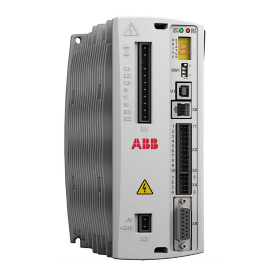
Page 23: Product Overview
Product overview Connections - front panel X1 Power LEDs The seven-segment display and the two EtherCAT LEDs are described in MicroFlex e150 indicators Earth/Ground page 119. Earth/Ground (NC) AC Phase 1/L AC Phase 2 / N AC Phase 3... -
Page 24: Connections - Top Panel
24 Hardware description Connections - top panel OPT1: Input / Output 14 Shield 7 DIN4 13 CREF1 6 DIN5 12 DIN8 5 DIN6 11 DIN9 4 DIN7 10 USRV+ 3 CREF0 DOUT5 2 DOUT3 DOUT6 1 DOUT4 E1 / E2 EtherCAT® EtherCAT (NC) EtherCAT... -
Page 25: Type Designation Label
A description of the product’s catalog numbering system is shown below: E152A09ENOA E152A09ENOA CAT. E152A09EIOA S/No. U0316010002 Desc. MicroFlex e150 Drive 9A MicroFlex e150 Drive 9A INPUT 105-250 AC 50/60 Hz 1 Ø/ Ø Typical label shown. OUTPUT 9A Cont/18A Pk 0-250V 3Ø, 3kW... - Page 26 26 Hardware description...
-
Page 27: Mechanical Installation
(6.84 cu.ft). If not installed in a cabinet, barriers around the equipment are required. • The MicroFlex e150 must be secured by the slots in the flange. The protective earth/ground (the threaded hole on the top of the MicroFlex e150) must be bonded to a safety earth/ground using either a 25 A conductor or a conductor of three times the peak current rating - whichever is the greater. -
Page 28: Required Tools
Check that there are no signs of damage. Notify the shipper immediately if damaged components are found. If MicroFlex e150 is to be stored for several weeks before use, be sure that it is stored in a location that conforms to the storage humidity and temperature specifications shown in on page 150. -
Page 29: Mounting And Cooling
• The 3 A model is designed to operate without any additional cooling methods. • The 6 A and 9 A models require a forced air flow, passing vertically from the bottom to the top of the MicroFlex e150 case, to allow full rated current at 45 °C (113 °F). -
Page 30: Effects Of Mounting Surface And Proximity
90 mm (3.5 in) to maintain effective cooling. Remember 90 mm that a MicroFlex e150 will be receiving air that has been already heated if it is mounted above another MicroFlex e150 or heat source. Multiple... -
Page 31: Installing
Mechanical installation 31 Installing 1. Mark the hole locations. See Dimension drawing (all models) page for complete dimensions. 167.7 mm (6.6 in) 63.5 mm (2.5 in) 2. Position the drive and check the hole positions are correct. 3. Drill the holes, mount the drive and tighten all four screws until the drive is secure. - Page 32 32 Mechanical installation...
-
Page 33: Planning The Electrical Installation
Note: The installation must always be completed according to applicable local laws and regulations. ABB does not assume any liability whatsoever for any installation which breaches the local laws and/or other regulations. Furthermore, if the recommendations given by ABB are not followed, the drive might experience problems that are not covered by the warranty. -
Page 34: European Union
34 Planning the electrical installation European Union To meet the European Union Machinery Directive, according to standard EN 60204-1, Safety of Machinery, the disconnecting device must be one of the following types: • a switch-disconnector of utilization category AC-23B (EN 60947-3) •... -
Page 35: Thermal Overload And Short Circuit Protection
UL compliance and provides protection for the wiring only, not the MicroFlex e150. Your local ABB representative can help you in selecting the breaker type when the supply network characteristics are known. -
Page 36: Selecting The Power Cables
36 Planning the electrical installation Selecting the power cables General rules Dimension the input power and motor cables according to local regulations. • The input power and the motor cables must be able to carry the corresponding load currents. See on page Electrical power network specification Motor... - Page 37 Planning the electrical installation 37 Alternative power cable types Motor cables (also recommended for supply cabling): Symmetrical shielded cable: three phase Note: A separate PE conductor is required conductors and a concentric or otherwise if the conductivity of the cable shield is not constructed PE conductor, and a shield.
-
Page 38: Protecting The Contacts Of Relay Outputs And Attenuating Inductive Loads
38 Planning the electrical installation Protecting the contacts of relay outputs and attenuating inductive loads Inductive loads (relays, contactors, motors) cause voltage transients when switched off. Equip inductive loads with noise attenuating circuits (varistors, RC filters [AC] or diodes [DC]) in order to minimize the EMC emission at switch-off. If not suppressed, the disturbances might connect capacitively or inductively to other conductors in the control cable and form a risk of malfunction in other parts of the system. -
Page 39: Selecting The Control Cables
Never mix 24 V DC and 115/230 V AC signals in the same cable. Relay cable The cable type with braided metallic screen (for example, ÖLFLEX by LAPPKABEL) has been tested and approved by ABB. Connection of a motor temperature sensor to the drive I/O on page 57. -
Page 40: Separate Control Cable Ducts
40 Planning the electrical installation A diagram of the cable routing is shown below: Power cable min. 300 mm (12 in) Motor cable Drive min. 500 mm (20 in) Control cables Separate control cable ducts Route 24 V and 230 V cables in separate ducts unless the 24 V cable is insulated for 230 V or insulated with an insulation sleeving for 230 V. - Page 41 AC power 10 mm (7 AWG) from fuses or reactor Mount AC filter and MicroFlex e150 on the same metal panel. Connect AC power cable shield to metal panel, using AC power wires should be as short as conductive shield possible, typically less than 0.3 m (1 ft).
- Page 42 42 Planning the electrical installation...
-
Page 43: Electrical Installation: Ac Input, Motor And Brake
Electrical installation: AC input, motor and brake 43 Electrical installation: AC input, motor and brake What this chapter contains The chapter describes how to connect input power cables, motor and brake resistor. WARNING! The work described in this chapter may only be carried out by a qualified electrician. -
Page 44: Checking The Insulation Of The Assembly
If further high potential (‘hipot’) testing is performed, use only DC voltages as AC voltage hipot tests could damage the drive. It is recommended to seek advice from your ABB sales representative before performing hipot tests. Input power cable Check the insulation of the input power cable according to local regulations before connecting to the drive. -
Page 45: Connecting The Power Cables
For CE compliance, an AC filter must be connected between the AC power supply and the MicroFlex e150. If local codes do not specify different regulations, use at least the same gauge wire for earth/ground as used for L1, L2 and L3. - Page 46 • Basic insulation. Earth leakage Maximum earth leakage from the MicroFlex e150 is 3.4 mA per phase (230 V, 50 Hz supply). This value does not include the earth leakage from the AC power filter, which could be much larger (see on page 166).
-
Page 47: Input Power Conditioning
• If the feeder or branch circuit that provides power to the MicroFlex e150 has permanently connected power factor correction capacitors, an input AC line reactor or an isolation transformer must be connected between the power factor correction capacitors and the MicroFlex e150 to limit the maximum symmetrical short circuit current to 5000 A. -
Page 48: Power Supply Filters
This can be supplied by ABB and will ensure that the MicroFlex e150 complies with the CE specifications for which it has been tested. Ideally, one filter should be provided for each MicroFlex e150; filters should not be shared between drives or other equipment. -
Page 49: Power Disconnect And Protection Devices
(L1 and L2 for example). When supplying AC power in this way, the voltage between the two phases must not exceed the rated input voltage of the MicroFlex e150. A two pole breaker must be used to isolate both lines. Fuses must be fitted in both lines. -
Page 50: Drive Overload Protection
50 Electrical installation: AC input, motor and brake Drive overload protection The MicroFlex e150 will immediately trip and disable if there is an overload condition. The parameters for managing drive overloads are configured automatically by the (page 100). If they need to be changed, use the... -
Page 51: 24 V Control Circuit Supply
I/O information. A separate fused 24 V supply should be provided for the MicroFlex e150. If other devices are powered from the same 24 V supply, a filter (part FI0014A00) should be installed to isolate the MicroFlex e150 from the rest of the system. -
Page 52: Motor Connections
The motor must be capable of being powered by an inverter PWM output. The motor can be connected directly to the MicroFlex e150 or through a motor contactor (M- Contactor). Motors should ideally have a minimum inductance of 1 mH per winding;... -
Page 53: Motor Power Cable Shielding
It is essential that the motor cable shield is correctly bonded to a functional earth, typically the same earthed metal backplane on which the MicroFlex e150 is mounted. The motor power output cable carries a high frequency high current waveform to the motor, so the cable’s shielding must be earthed to prevent the cable radiating... - Page 54 Carefully remove excess sheath at the end of the cable. from from MicroFlex e150 MicroFlex e150 Optional Motor Cable Management Bracket OPT-CM-001 (recommended) Metal P-clip Continuation of motor power cable shielding When using a motor contactor, or extending the motor cable through a terminal box, ensure that the motor cable shielding is continued all the way to the motor.
-
Page 55: Motor Circuit Contactors
Contactor ensures that the MicroFlex e150 cannot drive the motor, which might be necessary during equipment maintenance or similar operations. If an M-Contactor is installed, the MicroFlex e150 must be disabled at least 20 ms before the M-Contactor is opened. If the M-Contactor is opened while the MicroFlex e150 is supplying voltage and current to the motor, the MicroFlex e150 can be damaged. - Page 56 Do not use the supply that is powering the MicroFlex e150 digital outputs. The brake wires often carry noise that could cause erratic drive operation or damage. The brake contacts must never be wired directly to the digital outputs.
-
Page 57: Thermal Switch Connection
24). This allows the Connections - top panel MicroFlex e150 to respond to motor over-temperature conditions. Using the Mint WorkBench Digital I/O tool, the input can be configured to be the motor temperature input. The Mint keyword MOTORTEMPERATUREINPUT can also be used to configure a digital input for this purpose. -
Page 58: Brake Resistor (Regeneration Resistor)
58 Electrical installation: AC input, motor and brake Brake resistor (regeneration resistor) An optional external brake resistor might be required to dissipate excess power from the internal DC-bus during motor deceleration. The brake resistor must have a resistance of at least 39 Ω, an inductance of less than 100 μH, and a minimum power rating of 44 W. -
Page 59: Electrical Installation: Input / Output
Electrical installation: input / output 59 Electrical installation: input / output What this chapter contains The chapter describes how to connect low voltage control signals. The following conventions will be used to refer to the inputs and outputs: I/O ... Input / Output AIN . -
Page 60: Analog I/O
60 Electrical installation: input / output Analog I/O The MicroFlex e150 provides: • Two 12-bit resolution ±10 V analog inputs. • One 12-bit resolution ±10 V analog output. An analog input receives the torque / velocity reference signal when operating as an analog drive (see CONTROLREFSOURCE in the Mint help file), or it can be used as a general purpose ADC input. -
Page 61: Analog Output Aout0
The shield connection should be made at one end only. In Mint, the analog output can be controlled using the DAC keyword. See the Mint help file for full details of DAC and other related DAC... keywords. Output circuit: MicroFlex e150 +15V Demand AOUT0 AD5530BRUZ ±100%... -
Page 62: Digital I/O
62 Electrical installation: input / output Digital I/O The MicroFlex e150 provides: • 10 general purpose digital inputs. • 2 dedicated Safe Torque Off (STO) inputs. • 7 general purpose digital outputs. Connector Digital input / Common Purpose output connection... -
Page 63: Using A Digital Input As A Drive Enable Input (Optional)
The choice depends on the accuracy required for the homing and the EtherCAT cycle-time: • The axis home switch can be wired to an input on the MicroFlex e150, and then mapped back to the master over EtherCAT;... -
Page 64: Digital Inputs - Safe Torque Off (Sto)
MicroFlex e150 to supply power to the motor. If an additional hardware drive enable input is used to control the MicroFlex e150, it must not be wired with the STO input circuit. The state of the STO inputs can be viewed using the Mint WorkBench Spy window's Axis tab. -
Page 65: Digital Inputs - General Purpose Din0, Din3
The inputs do not share a common reference. When the MicroFlex e150 is connected to Mint WorkBench, the digital inputs can be configured using the Digital I/O tool. Alternatively, Mint keywords including DRIVEENABLEINPUT, RESETINPUT, ERRORINPUT and STOPINPUT can be used. -
Page 66: Digital Inputs - General Purpose Din1, Din2
The inputs do not share a common reference. When the MicroFlex e150 is connected to Mint WorkBench, the digital inputs can be configured using the Digital I/O tool. Alternatively, Mint keywords including DRIVEENABLEINPUT, RESETINPUT, ERRORINPUT and STOPINPUT can be used. -
Page 67: Special Functions On Inputs Din1, Din2
Electrical installation: input / output 67 Special functions on inputs DIN1, DIN2 DIN1 and DIN2 can be configured to perform special functions. Step (pulse) and direction inputs DIN1 and DIN2 can be configured using the statement ENCODERMODE(1)=4 to become step and direction inputs: •... -
Page 68: Digital Inputs - General Purpose Din4 - Din9
Inputs DIN4 and DIN5 share a common reference, CREF1. Inputs DIN6 - DIN9 share a common reference, CREF0. When the MicroFlex e150 is connected to Mint WorkBench, the digital inputs can be configured using the Digital I/O tool. Alternatively, Mint keywords including DRIVEENABLEINPUT, RESETINPUT, ERRORINPUT and STOPINPUT can be used. -
Page 69: Status Output (Dout0)
The status output becomes active in the event of an error, or when the STO function is activated. When the MicroFlex e150 is connected to Mint WorkBench, the active level of the output can be configured using the Digital I/O tool. Alternatively, the Mint keyword OUTPUTACTIVELEVEL can be used. -
Page 70: Digital Outputs Dout1, Dout2
DOUT1- User supply When the MicroFlex e150 is connected to Mint WorkBench, the active level of the outputs can be configured using the Digital I/O tool. Alternatively, the Mint keyword OUTPUTACTIVELEVEL can be used. The state of the outputs is displayed in the Spy... -
Page 71: Digital Outputs Dout3 - Dout6
Electrical installation: input / output 71 DOUT1 - typical connections to an ABB NextMove e100: User NextMove e100 / controller MicroFlex e150 supply 24 V DOUT1+ DOUT1- DIN4 TLP127 CREF1 TLP280 User supply Digital outputs DOUT3 - DOUT6 Location: OPT1, pin 2 (DOUT3), 1 (DOUT4), 9 (DOUT5), 8 (DOUT6), 10 (USRV+) The optically isolated general purpose outputs are designed to source current from a common user supply (USRV+). - Page 72 72 Electrical installation: input / output When the MicroFlex e150 is connected to Mint WorkBench, the active level of the outputs can be configured using the Digital I/O tool. Alternatively, the Mint keyword OUTPUTACTIVELEVEL can be used. The state of the outputs is displayed in the Spy window.
-
Page 73: Usb Interface
USB interface Location: U1 The USB connector is used to connect the MicroFlex e150 to a PC running Mint WorkBench. The MicroFlex e150 is a self-powered, USB 2.0 (12 Mbps) compatible device. If it is connected to a slower USB 1.0 host PC or hub, communication speed will be limited to the USB 1.0 specification (1.5 Mbps). - Page 74 Note: The MicroFlex e150 and other ABB equipment use ‘big endian’ word order and byte order for Modbus protocols. If this is incompatible with other Modbus equipment, the word and byte order for the MicroFlex e150 can be changed in Mint WorkBench. See the Mint WorkBench help file for details.
-
Page 75: Ethernet Interface
Note: The MicroFlex e150 and other ABB equipment use ‘big endian’ word order and byte order for Modbus protocols. If this is incompatible with other Modbus equipment, the word and byte order for the MicroFlex e150 can be changed in Mint WorkBench. See the Mint WorkBench help file for details. -
Page 76: Ethercat
76 Electrical installation: input / output EtherCAT® MicroFlex e150 supports the EtherCAT protocol. This protocol provides deterministic communication over a standard 100 Mbit/s (100Base-TX) Fast Ethernet (IEEE 802.3u) connection. This makes it suitable for the transmission of control and feedback signals between the MicroFlex e150 and other EtherCAT enabled controllers. -
Page 77: Ethercat Configuration
MicroFlex e150 provides an EtherCAT Slave Information (ESI) file. This .xml file describes the drive’s capabilities to the EtherCAT manager. The ESI file can be uploaded from the MicroFlex e150 using the Configuration tool in Mint WorkBench. -
Page 78: Ethernet Connectors
Recommended cables are listed in on page 172. Crossover or Ethernet cables straight cables can be used. Many Ethernet devices, including hubs and ABB e100 / e150 products, incorporate Auto-MDIX switching technology which automatically compensates for the wiring of straight cables. -
Page 79: Dip Switches
Electrical installation: input / output 79 DIP switches Location: SW1 The MicroFlex e150 has four DIP switches which allow special settings to be selected on power up. Changing the switch positions after power up has no effect. DIP switch settings:... -
Page 80: Motor Feedback
80 Electrical installation: input / output Motor feedback Location: X8 MicroFlex e150 supports incremental encoder, encoder with BiSS (Bi-directional Synchronous Serial Interface) or SSI (Synchronous Serial Interface), EnDat or Smart Abs absolute encoder, or SinCos encoder feedback, for use with linear and rotary motors. -
Page 81: Incremental Encoder Interface
Connector X8 includes a ‘Sense' pin, which is used to detect the voltage drop on long cable runs. This allows the MicroFlex e150 to increase the encoder supply voltage on pin 12 to maintain a 5 V supply at the encoder (400 mA max). - Page 82 Encoders without Halls Incremental encoders without Hall feedback connections can be connected to the MicroFlex e150. However, if Hall connections are not present, it will be necessary for the MicroFlex e150 to perform an automatic phase search sequence each time it is powered.
-
Page 83: Biss Interface
Electrical installation: input / output 83 Halls-only feedback devices Feedback devices using only Hall sensors can be connected to the MicroFlex e150. However, since there are no encoder connections, the MicroFlex e150 will not be able to perform smooth speed control or accurate positioning control. -
Page 84: Ssi Interface
The SSI (Synchronous Serial Interface) encoder interface is specifically designed for use with Baldor SSI motors, which incorporate a custom Baumer SSI encoder. Contact ABB technical support to confirm compatibility of other SSI devices. The SSI encoder connections are made using the 15-pin D-type female connector X8. -
Page 85: Smart Abs Interface
Electrical installation: input / output 85 Smart Abs interface The Smart Abs encoder connections are made using the 15-pin D-type female connector X8. Smart Abs interface cable connections: Motor Twisted pairs Data+ Absolute Connect Data- Encoder internal shields to pin 13. -
Page 86: Extra Incremental Encoder Interface
The 5 V encoder inputs (CHA, CHB and CHZ) can be used as differential inputs (recommended for improved noise immunity) or single ended inputs. When used as single ended inputs, leave the CHA-, CHB- and CHZ- pins unconnected. Extra encoder input circuit - channel A shown: MicroFlex e150 CHA+ MAX3096 Differential... -
Page 87: Installation Checklist
Installation checklist 87 Installation checklist This chapter contains a list for checking the mechanical and electrical installation of the drive. Checklist Check the mechanical and electrical installation of the drive before start-up. Go through the checklist together with another person. WARNING! Only qualified electricians are allowed to carry out the work described below. -
Page 88: Safe Torque Off (Sto) Connections
The test must be documented and signed by the authorized person. The MicroFlex e150 will operate only when the STO inputs are powered. on page 173. Appendix: Safe Torque Off (STO) -
Page 89: Start-Up
This chapter describes software installation and the start-up procedure of the drive. Introduction Before powering the MicroFlex e150 you will need to connect it to the PC using a USB or Ethernet cable and install the Mint WorkBench software. This includes a number of applications and utilities to allow you to configure, tune and program the MicroFlex e150. -
Page 90: Connecting The Microflex E150 To The Pc
The MicroFlex e150 can be connected to the PC using either USB or TCP/IP. To use USB, connect a USB cable between a PC USB port and the MicroFlex e150 USB port. Your PC must be using Windows XP, Windows Vista or Windows 7. -
Page 91: Starting The Microflex E150
5. To allow the Commissioning Wizard to function, the Safe Torque Off inputs (page 173) need to be powered to allow the MicroFlex e150 to be enabled. 6. If you do not wish to enable the MicroFlex e150 yet, the Commissioning Wizard will inform you when this step is necessary. - Page 92 92 Start-up To confirm that the USB driver is installed, check that a Motion Control category is listed in Windows Device Manager:...
-
Page 93: Configuring The Tcp/Ip Connection (Optional)
Start-up 93 Configuring the TCP/IP connection (optional) If you have connected the MicroFlex e150 to the PC using the Ethernet connection, it might be necessary to alter the PC's Ethernet adapter configuration to operate correctly with the MicroFlex e150. By default, the MicroFlex e150 has a static IP address of 192.168.100.110. This can be changed using the Configuration tool in Mint WorkBench. -
Page 94: Mint Machine Center
It is used to view the network of connected controllers in a system. Individual controllers and drives are configured using Mint WorkBench. If you have only a single MicroFlex e150 connected to your PC, then MMC is probably not required. See... -
Page 95: Starting Mmc
In the information pane, click Scan. 3. When the search is complete, click once on ‘MicroFlex e150' in the controller pane to select it, then double click to open an instance of Mint WorkBench. The MicroFlex e150 will be already connected to the instance of Mint WorkBench, ready to configure. -
Page 96: Mint Workbench
Mint WorkBench Mint WorkBench is a fully featured application for programming and controlling the MicroFlex e150. The main Mint WorkBench window contains a menu system, the Toolbox and other toolbars. Many functions can be accessed from the menu or by clicking a button - use whichever you prefer. -
Page 97: Help File
Start-up 97 Help file Mint WorkBench includes a comprehensive help file that contains information about every Mint keyword, how to use Mint WorkBench and background information on motion control topics. The help file can be displayed at any time by pressing F1. On the left of the help window, the Contents tab shows the tree structure of the help file;... -
Page 98: Starting Mint Workbench
98 Start-up Starting Mint WorkBench Note: If you have already used MMC to install firmware and start an instance of Mint WorkBench, go straight to section 6.4.3 to continue configuration. 1. On the Windows Start menu, select Programs, Mint WorkBench, Mint WorkBench. - Page 99 When the search is complete, click MicroFlex e150 in the list, then click Select. Note: If the MicroFlex e150 is not listed, check the USB or serial cable between the MicroFlex e150 and the PC. Check that the MicroFlex e150 is powered correctly.
-
Page 100: Commissioning Wizard
By monitoring the drive's output and the feedback from the motor's encoder, the MicroFlex e150 can make small adjustments to the way it controls the motor. This information is stored in the MicroFlex e150 and can be uploaded to a file if necessary. - Page 101 Mint WorkBench. Although the MicroFlex e150 might eventually be controlled over EtherCAT, the ‘RT Ethernet' reference source should only be selected after the MicroFlex e150 has been commissioned and is ready to add to the EtherCAT network. This can be selected by choosing the Operating Mode tool in the Toolbox.
- Page 102 This screen confirms that operation setup is complete. Autotune Wizard The Autotune Wizard tunes the MicroFlex e150 for optimal performance with the attached motor. This removes the need for manual fine-tuning of the system, although in some critical applications this still might be required.
-
Page 103: Further Tuning - No Load Attached
Further tuning - no load attached The Autotune Wizard calculates many parameters that allow the MicroFlex e150 to provide good control of the motor. In some applications, these parameters might need to be fine-tuned to provide the exact response that you require. - Page 104 104 Start-up Typical autotuned response (no load): Measured velocity Demand velocity Note: The graph that you see will not look exactly the same as this one! Each motor has a different response. The graph shows that the response reaches the demand quickly and only overshoots the demand by a small amount.
-
Page 105: Further Tuning - With Load Attached
Start-up 105 Further tuning - with load attached To allow Mint WorkBench to adjust the basic tuning to compensate for the intended load, it is necessary to attach the load to the motor and then perform the autotune procedure again. 1. -
Page 106: Optimizing The Velocity Response
106 Start-up Optimizing the velocity response It might be desirable to optimize the default autotuned response to better suit your application. The following sections describe the two main tuning factors and how to correct them. Correcting overshoot The following graph shows a response where the measured velocity overshoots the demand by a significant amount. - Page 107 Start-up 107 Correcting zero-speed noise in the velocity response The following graph shows a response where there is very little overshoot but a significant amount of zero-speed noise. This can cause undesirable humming or ringing in the motor. 1. Go to the Fine-tuning window's Velocity tab.
- Page 108 108 Start-up Ideal velocity response Repeat the tests described in Correcting overshoot Correcting zero-speed noise until the optimal response is achieved. The following graph in the velocity response shows an ideal velocity response. There is only a small amount of overshoot and very little zero-speed noise.
-
Page 109: Performing Test Moves - Continuous Jog
Start-up 109 Performing test moves - continuous jog This section tests the basic operation of the drive and motor by performing a continuous jog. To stop a move in progress, click the red stop button or the drive enable button on the toolbar. Alternatively, use the Mint WorkBench ‘Red Stop Button’ feature. -
Page 110: Performing Test Moves - Relative Positional Move
110 Start-up Performing test moves - relative positional move This section tests the basic operation of the drive and motor by performing a positional move. To stop a move in progress, click the red stop button or the drive enable button on the toolbar. -
Page 111: Further Configuration
Mint WorkBench provides a number of other tools for testing and configuring the MicroFlex e150. Every tool is explained fully in the help file. Press F1 to display the help file, then navigate to the Mint WorkBench book. Inside this is the Toolbox book. -
Page 112: Parameters Tool
The icon to the left of the item will become yellow to indicate that the value has been changed. Many of the MicroFlex e150's parameters are set automatically by the Commissioning Wizard, or when tests are performed in the fine-tuning window. -
Page 113: Spy Window
Start-up 113 Spy window The Spy window can be used to monitor and capture parameters in real-time. If you tried the test moves in on page Performing test moves - continuous jog on page then you have already Performing test moves - relative positional move seen the Spy window, as it is displayed in conjunction with Edit &... -
Page 114: Other Tools And Windows
This tool provides a work area including the Command window and Output window. The Command window can be used to send immediate Mint commands to the MicroFlex e150. If you tried the test moves in Performing test moves - on page... -
Page 115: Safe Torque Off (Sto) Acceptance Test
Start-up 115 Safe Torque Off (STO) acceptance test Drive commissioning is not complete until the STO function has been tested. The acceptance test of the safety function must be carried out by an authorized person with expertise and knowledge of the safety function. The test must be documented and signed by the authorized person. - Page 116 116 Start-up...
-
Page 117: Fault Tracing
Problem diagnosis If you have followed all the instructions in this manual in sequence, you should have few problems installing the MicroFlex e150. If you do have a problem, read this section first. • In Mint WorkBench, use the Error Log tool to view recent errors and then check the help file. -
Page 118: Supportme Feature
Power-cycling the MicroFlex e150 The term ‘power-cycle the MicroFlex e150’ is used in the Troubleshooting sections. Remove the 24 V supply, wait for the MicroFlex e150 to power down completely (the Status LED will turn off), then re-apply the 24 V supply. -
Page 119: Microflex E150 Indicators
Fault tracing 119 MicroFlex e150 indicators Ethernet LEDs The Ethernet LEDs display the overall condition of the Ethernet interface once the startup sequence has completed. The LED codes conform to the EtherCAT Technology Group (ETG) standard at the time of production. - Page 120 120 Fault tracing NET RUN (Green) Off: INITIALISATION state (or not powered). Blinking: PRE-OPERATIONAL state. 1 flash: SAFE-OPERATIONAL state. 3 flashes: Device identification. This state can be set from the master to locate the device. Continuously illuminated, not flashing: Node in OPERATIONAL state. EtherCAT is operating normally.
-
Page 121: Drive Status Display
Drive status display The drive status display indicates errors and general MicroFlex e150 status information. When an error occurs, the drive displays a sequence starting with the symbol E, followed by the five digit error code. For example, error code 10015 is... - Page 122 122 Fault tracing Symbol Description Homing. The drive is currently homing. See the Mint keyword HOME Incremental move. An incremental linear move is in progress. See the Mint keywords INCA INCR Jog. The drive is jogging. See the Mint keywords JOGCOMMAND related topics.
-
Page 123: Power
• Check that the 24 V DC control circuit supply is correctly connected at X2, and is switched on. Drive status display shows ‘r’: • The MicroFlex e150 is in firmware recovery mode. This means that it cannot boot fully, so will allow Mint WorkBench to download firmware from the scan controller dialog. -
Page 124: Tuning
USB: • Check that the MicroFlex e150 is powered. • Check that a ‘ABB USB Motion Product’ device is listed in Windows Device Manager, and 'MicroFlex e150' is listed in Windows Devices and Printers (Windows 7). If not, there could be a problem with the PC's USB interface. - Page 125 I can’t control the MicroFlex e150 from my EtherCAT manager The drive’s reference source must be set to allow the EtherCAT manager to take control of the MicroFlex e150. There are several ways to do this: • Set the CONTROLREFSOURCESTARTUP parameter to '1' using the Mint WorkBench Parameter viewer or Command window, and restart the drive.
- Page 126 126 Fault tracing...
-
Page 127: Technical Data
Technical data 127 Technical data What this chapter contains The chapter contains the technical specifications of the drive, for example, the ratings, sizes and technical requirements as well as provisions for fulfilling the requirements for CE and other marks. -
Page 128: Dimension Drawing (All Models)
128 Technical data Dimension drawing (all models) (3.23) 79.5 (3.13) 63.4 (0.4) (2.5) (0.2) Dimensions shown as: mm (inches) Depth: 157 mm (6.2 in) Weight: 3 A: 1.45 (3.2 lb) 6 A: 1.50 kg (3.3 lb) 9 A: 1.55 kg (3.4 lb) -
Page 129: Electrical Power Network Specification
136. * The MicroFlex e150 will operate at lower input voltages, although the drive will trip if the DC-bus voltage falls below 50 V or 60% of the no-load voltage, whichever occurs... -
Page 130: Effect Of Ac Power Supply Voltage On Dc-Bus Voltage
130 Technical data Effect of AC power supply voltage on DC-bus voltage Three-phase AC supply Single-phase AC supply AC supply voltage (rms) Effect of AC power supply voltage on DC-bus ripple voltage Single-phase AC supply Three-phase AC supply AC supply voltage (rms) -
Page 131: Effect Of Output Current On Dc-Bus Ripple Voltage
Technical data 131 Effect of output current on DC-bus ripple voltage Single-phase AC supply Three-phase AC supply % of drive rated current... -
Page 132: Temperature Derating
The derating characteristics assume the MicroFlex e150 is mounted vertically on 3 mm thick (or less) metal plate. If the MicroFlex e150 is mounted on 10 mm metal plate, the current characteristics shown below can be increased by up to 7% if there is no forced air cooling, or 15% if forced air cooling is present. -
Page 133: Derating Characteristic For 6 A Models (E152A06
Technical data 133 Derating characteristic for 6 A models (E152A06...): Single-phase AC supply 1.5 m/s forced air 1 m/s forced air Natural cooling Ambient temperature (°C) Three-phase AC supply 1.5 m/s forced air 1 m/s forced air Natural cooling Ambient temperature (°C) Notes: Load power factor = 0.75. -
Page 134: Derating Characteristic For 9 A Models (E152A09
Overtemperature trips The MicroFlex e150 contains internal temperature sensors that will cause it to trip and disable if the temperature exceeds 80 °C (3 A model), or 75 °C (6 A and 9 A models). This limit can be read using the TEMPERATURELIMITFATAL keyword - see... -
Page 135: Heat Dissipation
Technical data 135 Heat dissipation These figures assume drive efficiency = 95%, power factor = 0.8: MicroFlex e150 Heat dissipation model... -
Page 136: Recommended Fuses, Circuit Breakers And Wire Sizes
136 Technical data Recommended fuses, circuit breakers and wire sizes The following table describes the recommended fuses and circuit breakers for AC power connections, and suitable wires sizes for AC and motor power connections. Drive Cont. Input fuse Circuit Minimum catalog output supply... -
Page 137: Input Power-Cycling And Inrush
Technical data 137 Input power-cycling and inrush If AC power has been removed from the MicroFlex e150, it should remain disconnected for the specified period before it is reapplied: MicroFlex e150 Minimum power cycle delay period current rating (seconds) This delay allows the input surge protection circuit to perform correctly, ensuring that the inrush current (typically 1.7 A) is below the drive rated current. -
Page 138: Power Supply Filters
Foot-mount filter (single phase only) Maximum earth leakage from the MicroFlex e150 is 3.4 mA per phase (230 V, 50 Hz supply). This value does not include the earth leakage from the AC power filter, which could be much larger (see on page 166). -
Page 139: Motor Output Power (X1)
Technical data 139 Motor output power (X1) Description Unit Nominal phase current Peak phase current for 3 s Nominal output 1195 2390 3585 @ 230 V, 3Φ Output voltage (line-line) 0 - 230 @ V DC-bus = 320 V Output frequency 0 - 2000 Output dV/dt kV/µs... -
Page 140: Brake (X1)
Minimum load resistance Ω Minimum load inductance µH Braking capacity The braking capacity of the MicroFlex e150 can be calculated from the following formula: E = — × DC bus capacitance × (Brake switching threshold) – 2 × Supply voltage where the Brake switching threshold is 388 V. - Page 141 Technical data 141 Requirement Enter value here a) Initial motor speed, before deceleration begins, Initial motor speed: in radians per second. U = _____________ rad/s Multiply RPM by 0.1047 to give radians per second. b) Final motor speed after deceleration is complete, Final motor speed: in radians per second.
-
Page 142: Braking Energy
142 Technical data Braking energy The braking energy to be dissipated, E, is the difference between the initial energy in the system (before deceleration begins) and the final energy in the system (after deceleration has finished). If the system is brought to rest then the final energy is zero. -
Page 143: Resistor Choice
Dimensions of brake resistors are shown in on page 169. Brake resistors * The brake resistors listed in the table above can withstand a brief overload of 10 times the rated power for 5 seconds. Please contact ABB if larger power ratings are required. -
Page 144: Resistor Derating
144 Technical data Resistor derating The brake resistors shown in the previous table can achieve their stated power rating only when mounted on a heat sink. In free air a derating must be applied. Furthermore, in ambient temperatures greater than 25 °C (77 °F), a temperature derating must be applied. -
Page 145: Input / Output
Technical data 145 Input / output Analog inputs AIN0, AIN1 (X4) Description Unit All models Type Differential Common mode voltage range V DC ±10 Common mode rejection Input impedance kΩ Input ADC resolution bits (includes sign bit) Equivalent resolution ±4.9 Sampling interval µs... -
Page 146: Digital Inputs Din0, Din3 (X3)
146 Technical data Digital inputs DIN0, DIN3 (X3) Description Unit All models Type Opto-isolated inputs Input voltage V DC Nominal Minimum Maximum Active > 12 Inactive < 2 Input current (maximum, per input) Sampling interval Minimum pulse width µs ... -
Page 147: Digital Outputs Dout0 (Status), Dout1, Dout2 (X3)
Technical data 147 Digital inputs DIN4 - DIN9 (OPT1) Description Unit All models Type Opto-isolated inputs Input voltage V DC Nominal Minimum Maximum Active > 12 Inactive < 2 Input current (maximum, per input) Sampling interval Minimum pulse width µs ... -
Page 148: Biss Encoder Interface (X8)
Differential Data and Clock Operating mode Single or multi-turn. (Baldor motors) A wide range of devices can be supported. Contact ABB technical support before selecting a device. Output power supply to encoder 5 V DC (±7%), 400 mA max.* Maximum recommended cable length 30.5 (100 ft) -
Page 149: Smart Abs Encoder Interface (X8)
512 or 2048 Sin/Cos cycles per turn, with absolute positioning resolution of up to 65536 steps. (Many other encoder specifications are supported - contact ABB.) Output power supply to encoder 5 V DC (±7%), 400 mA max.* Maximum recommended cable length 30.5 (100 ft) ... -
Page 150: Ambient Conditions
150 Technical data Ambient conditions Description Unit All models Operating temperature range °C °F Minimum V DC Maximum +113 Derate Temperature Temperature on page on page derating derating 132. 132. Storage temperature range -40 to +85 -40 to +185 Humidity (maximum) Forced air cooling flow None (vertical, from bottom to top) -
Page 151: Applicable Standards
EN 60529:1991 + A1:2000 Degrees of protection provided by enclosures. EN 61800-3:2004 Electromagnetic compatibility. When installed as directed in this manual, MicroFlex e150 conforms to the category C2 emission limits and the ‘second environment’ immunity requirements defined by this standard. - Page 152 152 Technical data EtherCAT Conformance Test Certificate...
-
Page 153: Degree Of Protection
Degree of protection MicroFlex e150 complies with EN 60529, IP20 provided connector X1 is shrouded. For UL purposes the MicroFlex e150 is defined as an open-type, single or three phase, single axis servo amplifier. The drive must be installed in a cabinet to fulfil the requirements for shielding from contact. -
Page 154: Compliance With The En 61800-3
154 Technical data Compliance with the EN 61800-3 Definitions EMC stands for Electromagnetic Compatibility. It is the ability of electrical/electronic equipment to operate without problems within an electromagnetic environment. Likewise, the equipment must not disturb or interfere with any other product or system within its locality. -
Page 155: Compliance With The European Machinery Directive
Technical data 155 WARNING! A drive of category C3 is not intended to be used on a low-voltage public network which supplies domestic premises. Radio frequency interference is expected if the drive is used on such a network. Compliance with the European Machinery Directive This safety related drive complies with the European Union Machinery Directive requirements for a safety component intended to be integrated into machinery. -
Page 156: Ce Declaration Of Conformity
2006/42/EC Machinery Directive Hereby declare that the following safety component: MicroFlex e150 Integrated safe-torque-off drive with type markings: E152A (followed by additional alpha-numeric digits to signify product variant) Is in conformity with the applicable requirements of the following documents: Standard:... -
Page 157: Ul Marking
Technical data 157 UL marking The MicroFlex e150 is C-UL US Listed only when used in conjunction with optional Fan Tray (part FAN001-024, see page 164). The approval is valid with rated voltages. When used without optional fan tray FAN001-024, the MicroFlex e150 is UL Recognized. -
Page 158: Control System
158 Technical data Control system The MicroFlex e150 can use two main control configurations: • Servo (Position). • Torque Servo (Current). The configuration is selected using the Mint CONFIG keyword (object 5000h), or by using the Mint WorkBench System Configuration Wizard. Each configuration... - Page 159 Technical data 159...
-
Page 160: Torque Servo Configuration
160 Technical data Torque servo configuration The diagram on page shows the torque-servo control configuration. Here, the velocity loop has been removed and the output of the position controller is fed into the current loop via the torque filters. The torque servo configuration is useful when the drive is operating as a closed-loop position controller and settling time must be minimized. - Page 161 Technical data 161...
- Page 162 162 Technical data...
-
Page 163: Accessories
What this chapter contains This section describes accessories and options that you might need to use with your MicroFlex e150. Shielded (screened) cables provide EMI / RFI shielding and are required for compliance with CE regulations. All connectors and other components... -
Page 164: Fan Tray
Fan tray The fan tray (part FAN001-024) provides sufficient cooling for the 6 A and 9 A MicroFlex e150. The fan tray might be required for the 3 A model when operating in high ambient temperatures (see on page 132). The fan tray Temperature derating requires 23 - 27.5 V DC at 325 mA, which can be sourced from the same filtered... -
Page 165: Foot-Mount Filter (Single Phase Only)
Foot-mount filter (single phase only) The single-phase foot-mount AC power filter (part FI0029A00) provides mounting holes for the MicroFlex e150 and fan tray. This allows the filter, fan tray and MicroFlex e150 to use minimal panel mounting space. See pages details of filter FI0029A00. -
Page 166: Emc Filters
EMC filters AC filters remove high frequency noise from the AC power supply, protecting the MicroFlex e150. These filters also prevent high frequency signals from being transmitted back onto the power lines and help meet EMC requirements. To select the correct filter, see... - Page 167 Accessories 167 Filter dimensions, types FI0014A00, FI0015A00, FI0015A02: Dimensions: mm (inches) Dimension FI0014A00 FI0015A00 FI0015A02 85 (3.35) 113.5 (4.47) 156 (6.14) 54 (2.13) 57.5 (2.26) 40 (1.57) 46.6 (1.83) 65 (2.56) 94 (3.70) 130.5 (5.14) 75 (2.95) 103 (4.06) 143 (5.63) 27 (1.06) 25 (0.98) 12 (0.47)
- Page 168 168 Accessories Filter dimensions, type FI0029A00: Mounting keyhole and slot detail G 5.5 mm H 11 mm K 5 mm 10 mm Dimensions mm (inches) Dimension FI0029A00 255 (10.04) 100 (3.94) 244.5 (9.63) 70 (2.76) 40 (1.57) 20 (0.79)
-
Page 169: Brake Resistors
Brake resistors Depending on the application, MicroFlex e150 might require an external brake resistor to be connected to pins R1 and R2 of connector X1. The brake resistor dissipates energy during braking to prevent an over-voltage error occurring. See... -
Page 170: Encoder Breakout
(see page 80). Alternatively, the connectors can be used together to connect a single motor that has separate cables for encoder and Halls (e.g. a linear motor). OPT-MF-200 OPT-MF-200 MicroFlex e150 Motor feedback Incremental encoder... -
Page 171: Cables
Accessories 171 Cables A wide range of motor and feedback cables are available. Motor power cables For easier installation, it is recommended that a color-coded motor power cable is used. The part number for a BSM rotary motor power cable is derived as follows: BSM style threaded motor Current Standard... -
Page 172: Feedback Cables
Other lengths available on request Example: A 2 m encoder feedback cable for a MicroFlex e150 drive, with required connectors at both ends, has part number CBL020SF-E2. These feedback cables have the outer shield tied to the connector housing(s). If you are using an alternative cable with your chosen feedback device, be sure to obtain a cable that is a shielded twisted pair 0.34 mm... -
Page 173: Appendix: Safe Torque Off (Sto)
(STO) What this chapter contains The appendix describes the basics of the Safe torque off function (STO) for the MicroFlex e150. In addition, application features and technical data for the safety system calculation are presented. Basics The STO function disables the control voltage of the power semiconductors of the drive output stage, which prevents the inverter generating the voltage required to rotate the motor (see diagram below). - Page 174 174 Appendix: Safe Torque Off (STO) Safety circuit MicroFlex e150 (emergency stop Safe Torque Off switch, relay etc. PWM control connections circuit X3:18 +24 V X3:8 X3:19 +24 V X3:9 Common +0 V PWM power circuit Integrated Power Drivers Module...
-
Page 175: Operation Of The Sto Function And Diagnostics
The state of the internal STO status output: SAFETORQUEOFF(6) 0 = fault, 1 = no fault See Safety Manual: Safe Torque Off (STO) function for MicroFlex e150 drives (LT0313...) for full details. Status display When an STO error occurs, the drive displays error code 10033, 10034 or 10035 on its front panel Drive Status display. -
Page 176: Installation
• after any maintenance work related to the safety function. If you connect an external Safe Torque Off circuit to the drive, perform the acceptance test for the Safe Torque Off function as described in Safety Manual: Safe Torque Off (STO) function for MicroFlex e150 drives (LT0313...). -
Page 177: Technical Data: Digital Inputs Sto1, Sto2 (X3)
Appendix: Safe Torque Off (STO) 177 Technical data: Digital inputs STO1, STO2 (X3) Description Unit All models Type Opto-isolated inputs Input voltage V DC Nominal Minimum Maximum Active > 12 Inactive < 2 Input current (maximum, per input) Sampling interval Minimum pulse width µs ... -
Page 178: Sto Function: Tüv Certificate
178 Appendix: Safe Torque Off (STO) STO function: TüV certificate... -
Page 179: Further Information
Product and service inquiries Address any inquiries about the product to your local ABB representative, quoting the type designation and serial number of the unit in question. A listing of ABB sales, support and service contacts can be found by navigating to www.abb.com/drives... - Page 180 Contact us ABB Oy ABB Inc. ABB Beijing Drive Systems Co. Ltd. Drives Automation Technologies No. 1, Block D, A-10 Jiuxianqiao Beilu P.O. Box 184 Drives & Motors Chaoyang District FI-00381 HELSINKI 16250 West Glendale Drive Beijing, P.R. China, 100015...