Advertisement
LG
PI485 for Outdoor Unit
INSTALLATION MANUAL
Models: PMNFP14A0
PMNFP14A1
PGNFP14A0
Visit us at : http://www.lgservice.com
IMPORTANT
• Please read this installation manual completely
before installing the product.
• Installation work must be performed in
accordance with the national wiring standards
by authorized personnel only.
• Please retain this installation manual for future
reference after reading it thoroughly.
LG
Advertisement
Table of Contents

Related Manuals for LG PMNFP14A0


Summary of Contents for LG PMNFP14A0
-
Page 1: Installation Manual
Visit us at : http://www.lgservice.com PI485 for Outdoor Unit INSTALLATION MANUAL Models: PMNFP14A0 PMNFP14A1 PGNFP14A0 IMPORTANT • Please read this installation manual completely before installing the product. • Installation work must be performed in accordance with the national wiring standards by authorized personnel only. -
Page 2: Table Of Contents
PI 485 INSTALLATION MANUAL TABLE OF CONTENTS Safety Precautions ............3~4 Part Description ..............5 Accessory Parts ..............6 Installation Guide ............7~11 I Installation Steps ..................7 I DIP Switch Configuration ................8 I Simple Central Controller Connection Diagram ........9 I PC / Deluxe Central Controller Connection Diagram ...... -
Page 3: Safety Precautions
Safety Precautions Safety Precautions To prevent injury to the user or other people and property damage, the following instructions must be followed. I Incorrect operation due to ignoring instruction will cause harm or damage. The seriousness is classified by the following indications. WARNING This symbol indicates the possibility of death or serious injury. - Page 4 Safety Precautions Use the correctly rated Do not install, remove, or re- For installation, always breaker or fuse. install the unit by yourself contact the dealer or an (customer). Authorized Service Center. • There is risk of fire or electric •...
-
Page 5: Part Description
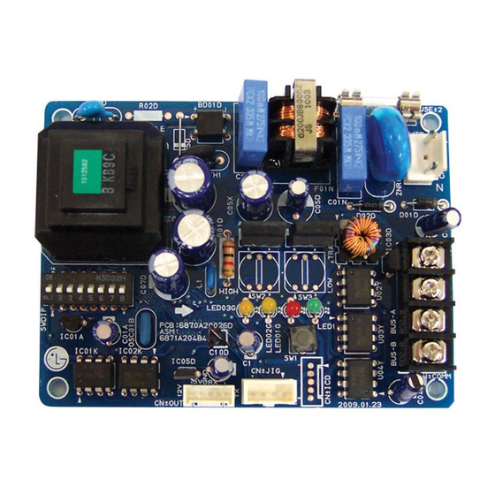
PMNFP14A0 / PMNFP14A1 / PGNFP14A0 ✽ The location of parts might be different in case of PMNFP14A1. PMNFP14A0 : For connecting 1 ~ 16 Indoor Units PMNFP14A1 : For connecting 1 ~ 48 Indoor Units PGNFP14A0 : For connecting only base controller... -
Page 6: I Accessory Parts
Acceassory Parts Acceassory Parts Multi-V PI485 : PMNFP14A0(1EA) BRACKET (1EA) or PMNFP14A1(1EA) SCREW (4EA) or PGNFP14A0(1EA) MPS Multi Multi-V WIRE ASSY 1(1EA) WIRE ASSY 2(1EA) WIRE ASSY 3(1EA) Others : Tie Wrap (3 EA) - Cable Tie Clamp (1 EA) -
Page 7: Installation Guide
Installation Guide Installation Guide Installation Steps Connect CN_OUT with Outdoor Unit by the cable (provided) Connect RS-485 BUS_A(+) and BUS_(B)(-) with other network products (ex. Central Controller , I-Gateway..) In case of using Simple Central Controller, connect VCC(+10V) and GND. No need to connect otherwise. -
Page 8: Dip Switch Configuration
Select Network Conditioner Type Type ON KSDO 4H * LGAP : LG Air conditioner Protocol Multi V & Multi(LGAP applied) products Configuration Methods ON KSDO4H 1 ON, All others OFF: Multi V products(Except CRUN products) or Multi(Non-Inverter) Product applied Common PCB(Refer to... -
Page 9: I Simple Central Controller Connection Diagram
Installation Guide Simple Central Controller - Connection Diagram MAIN PCB PI485 MAIN PCB Control Box CN_CENTRAL MAIN PCB CN_CENTRAL PI485 CN_OUT CAUTION: After product installation, tie the cables with Clamps & Tie-Wraps provided. Check the right connection of each BUS A and BUS B. Installation Manual 9... -
Page 10: I Pc / Deluxe Central Controller Connection Diagram
Installation Guide PC/ Deluxe Central Controller - Connection Diagram Outdoor PCB BUS_A BUS_B CN_CENTRAL • In case of Multi V, either connect MULTI OUTDOOR TERMINAL BLOCK PI485 to Multi V terminal block or connect it directly to the CNU PCB D VCC GND as shown here. -
Page 11: I How To Connect The Base Station Controller
Installation Guide How to connect the base station controller • PGNFP14A0 (Only) Connecting the PI 485 communication line BUS_B BUS_A Aircon Indoor unit #1 (Control address : 01) POWER EREOR BUS_B BUS_A RUN/STOP MODE RESET Base station controller Indoor unit #1 (Control address : 02) [Steps to connect] *Note: See the PI 485 manual for the internal setting. - Page 12 Memo 12 485 Gateway(M)
- Page 13 P/No.: MFL37115809 Printed in Korea After reading this manual, keep it in a place easily accessible to the user for future reference.