Table of Contents
Advertisement
IMPORTANT SERVICE NOTES (FOR U.S.A. ONLY) ...................................................................................................... 2
SPECIFICATIONS ............................................................................................................................................................ 2
NAMES OF PARTS .......................................................................................................................................................... 3
OPERATION MANUAL ..................................................................................................................................................... 5
DISASSEMBLY ................................................................................................................................................................. 8
REMOVING AND REINSTALLING THE MAIN PARTS .................................................................................................. 10
ADJUSTMENT ................................................................................................................................................................ 12
TEST MODE ................................................................................................................................................................... 13
ERROR LIST .................................................................................................................................................................. 17
NOTES ON SCHEMATIC DIAGRAM ............................................................................................................................. 18
TYPES OF TRANSISTOR AND LED .............................................................................................................................. 18
WAVEFORMS OF CD CIRCUIT ..................................................................................................................................... 19
BLOCK DIAGRAM .......................................................................................................................................................... 20
SCHEMATIC DIAGRAM ................................................................................................................................................. 24
WIRING SIDE OF P.W.BOARD ...................................................................................................................................... 30
TROUBLESHOOTING .................................................................................................................................................... 34
FUNCTION TABLE OF IC .............................................................................................................................................. 40
LCD SEGMENT .............................................................................................................................................................. 48
PARTS GUIDE/EXPLODED VIEW
SERVICE MANUAL
CONTENTS
MICRO COMPONENT SYSTEM
MODEL
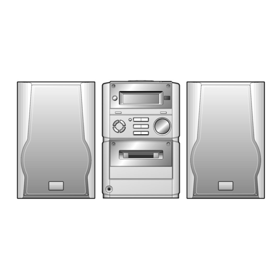
XL-70 Micro Component System consisting of XL-70 (main unit) and
CP-XL70U (speaker system).
MODEL
XL-70C Micro Component System consisting of XL-70C (main unit)
and CP-XL70U (speaker system).
• In the interests of user-safety the set should be restored to its original
condition and only parts identical to those specified should be used.
This document has been published to be used
for after sales service only.
The contents are subject to change without notice.
XL-70/70C
No. S5037XL-70///
XL-70
XL-70C
Page
Advertisement
Table of Contents

Related Manuals for Sharp XL-70


Summary of Contents for Sharp XL-70
-
Page 1: Table Of Contents
XL-70/70C SERVICE MANUAL No. S5037XL-70/// MICRO COMPONENT SYSTEM XL-70 MODEL XL-70 Micro Component System consisting of XL-70 (main unit) and CP-XL70U (speaker system). XL-70C MODEL XL-70C Micro Component System consisting of XL-70C (main unit) and CP-XL70U (speaker system). • In the interests of user-safety the set should be restored to its original condition and only parts identical to those specified should be used. -
Page 2: Important Service Notes (For U.s.a. Only)
XL-70/70C FOR A COMPLETE DESCRIPTION OF THE OPERATION OF THIS UNIT, PLEASE REFER TO THE OPERATION MANUAL. IMPORTANT SERVICE NOTES (FOR U.S.A. ONLY) BEFORE RETURNING THE AUDIO PRODUCT (Fire & Shock Hazard) Before returning the audio product to the user, perform the following safety checks. -
Page 3: Names Of Parts
XL-70/70C NAMES OF PARTS XL-70/70C 1 2 3 Front panel 1. Timer Indicator 2. Record Indicator 3. Sleep Indicator 4. (CD) Random Indicator 5. (CD/TUNER) Memory Indicator 6. FM Stereo Mode Indicator 7. FM Stereo Indicator 8. (CD) Play Indicator 9. -
Page 4: Tuner Control Section
XL-70/70C CP-XL70U 1. Tweeter 2. Woofer 3. Bass Reflex Duct 4. Speaker Wire XL-70/70C Remote control 1. Remote Control Transmitter LED Tuner control section 2. Preset Up/Down Buttons CD control section 3. Clear Button 4. Random/Repeat Button 5. Memory Button 6. -
Page 5: Operation Manual
XL-70/70C OPERATION MANUAL – 5 –... - Page 6 XL-70/70C – 6 –...
- Page 7 XL-70/70C – 7 –...
-
Page 8: Disassembly
XL-70/70C DISASSEMBLY XL-70/70C Caution on Disassembly Follow the below-mentioned notes when disassembling (A1)x1 Top Cabinet the unit and reassembling it, to keep it safe and ensure ø3x10mm CD PWB excellent performance: (B2)x1 1. Take cassette tape and compact disc out of the unit. - Page 9 XL-70/70C CP-XL70U Front Panel STEP REMOVAL PROCEDURE FIGURE Speaker 1. Net Frame ... (A1) x1 2. Screw ....(A2) x4 2. Woofer Ring ..(A3) x1 4. Screw ....(A4) x4 Tape Mechanism Open Tweeter Cassette (K1)x4 Holder (A1)x1 ø2.5x10mm (A4)x4 ø3x12mm...
-
Page 10: Removing And Reinstalling The Main Parts
XL-70/70C REMOVING AND REINSTALLING THE MAIN PARTS TAPE MECHANISM SECTION (A2)x1 (A2)x1 ø2x7mm ø2x3mm Perform steps 1 to 8 and 10 of the disassembly method to remove the tape mechanism. (See page 8.) (A1)x2 ø2x8mm How to remove the record / playback and erase heads (See Fig. -
Page 11: Cd Mechanism Section
XL-70/70C How to remove the tape mechanism PWB (F1)x1 (F2)x1 ø2x3mm (See Fig. 11-1.) Tape ø2x8mm Mechanism 1. Remove the screws (F1) x 1 pc., to remove the tape Tape mechanism PWB. Mechanism 2. Remove the screws (F2) x 1 pc. -
Page 12: Adjustment
XL-70/70C ADJUSTMENT MECHANISM SECTION • Driving Force Check • FM Mute Level Signal generator: 1 kHz, 40 kHz dev., FM modulated Torque Meter Specified Value Adjusting Frequency Display Instrument Play: TW-2412 Over 80 g Parts Connection • Torque Check 98.00 MHz 98.00 MHz... -
Page 13: Test Mode
XL-70/70C TEST MODE The test mode applied to this microcomputer has three modes, namely ordinary test mode to be used for adjustment or measurement, aging test mode to be used for aging test, and self-diagnosis test mode for self-inspection in case of final product inspection. - Page 14 XL-70/70C 2. Step 2 Mode When the "PLAY" button is pressed in this mode, the laser lighting command LDON (8400) is sent, and the laser is turned on. Other operations are not performed. If the following buttons are pressed in this state, the operation is performed as follows.
- Page 15 XL-70/70C 5. Step 5 Mode The CD initialization operation flow is executed to the end, the mute is set to off, and playback is started. Even when the playback reaches the outermost periphery of disc, the operation does not stop. The LCD display indicates the playback past time as in case of ordinary CD playback.
- Page 16 XL-70/70C 3. Preset frequencies for various destinations (random preset memory) BAND U.S.A. ,Brazil BAND U.S.A. ,Brazil FM 87.5 MHz FM108.0 MHz FM STEREO FM 98.0 MHz FM 90.0 MHz FM106.0 MHz AM 530 kHz AM1720 kHz AM 990 kHz AM 600 kHz AM1400 kHz FM106.0 MHz...
-
Page 17: Error List
XL-70/70C 7. Key input diagnosis Test Mode (TEST 6) When the test mode is set, the following indication appears. This test mode is intended to check whether all the main unit buttons can be detected. Accordingly, in this test mode checking as to whether the "POWER"... -
Page 18: Notes On Schematic Diagram
XL-70/70C NOTES ON SCHEMATIC DIAGRAM • Resistor: • The indicated voltage in each section is the one measured To differentiate the units of resistors, such symbol as K and by Digital Multimeter between such a section and the chas- M are used: the symbol K means 1000 ohm and the symbol sis with no signal given. -
Page 19: Waveforms Of Cd Circuit
XL-70/70C WAVEFORMS OF CD CIRCUIT NO DISC FOCUS SEARCH STOP PLAY TMAX IC802 48pin IC802 30pin SBOK IC804 26pin IC802 12pin IC804 25pin IC802 55pin FOCUS SEARCH TOC IL STOP PLAY IC802 57pin IC802 46pin IC802 43pin IC802 49pin IC802 46pin... -
Page 20: Block Diagram
XL-70/70C R_MUT AM LOOP Q351 ANTENNA CNP301 AM OSC OUT SWITCHING L341 T302 X351 VD301-1 BALUN 456kHz AM ANT SVC348S VR351 10K(B) 14 13 MUTE LEVEL VD301-2 SVC348S IC303 T306 FM IF DET./FM MPX./AM IF AM OSC. LA1832 T351 ZD351 AM MIX MTZJ5.1B... - Page 21 XL-70/70C R_MUTE SWITCHING CNS704 FM ST DISPLAY CD+B P MUTE P-STB J5.1B A_12V R-CH OUT REC R CH AUX R TAPE R TUN R CD R R-CH VIDEO/ IC401 INPUT FUNCTION/VOLUME EQUALIZER LOGIC SO401 L-CH LC75342M R-MUTE WOOFER CD L...
- Page 22 XL-70/70C LCD701 LCD DISPLAY COM3 COM2 COM1 COM0 VLC3 VLC2 VLC1 OSC2 OSC1 X701 8MHz IC701 IX0026SJ X702 SYSTEM CONTROL MMOD 32.768kHz MICROCOMPUTER SW700 CNS706 CNP706 VREF CLID_SW SW709-SW710 KEY1 DOWN SW711-SW713 KEY2 D701-709 SW721-SW728 MODEL CLID_PRO D_GND TAPE_SW CFW701...
- Page 23 XL-70/70C LCD DISPLAY CL ID_DW CLID_UP CLID_PRO CL ID_SW SEG25 CD_RES SEG26 SEG27 BUCK TO CD PWB SEG28 BUS3 SEG29 BUS2 SEG30 BUS1 SEG31 BUS0 SEG32 CD_STB SEG33 PU_IN CNS702 BUCK IC701 BUS3 IX0026SJ BUS2 YSTEM CONTROL BUS1 ICROCOMPUTER BUS0...
-
Page 24: Schematic Diagram
XL-70/70C AM TRACKING fL FM MUTE LEVEL AM ANT SWITCHING C330 C343 12P(CH) R358 VR351 8.2K C332 C331 10K(B) 0.022 VD301 0.047 4.7V T302 SVC348S (0V) C371 L353 R361 C329 D301 1/50 0.022 1N4148 R362 AM BAND COVERAGE fL R323... - Page 25 XL-70/70C FM SIGNAL AM SIGNAL PLAYBACK SIGNAL RECORD SIGNAL CD SIGNAL IC401 FUNCTION/VOLUME EQUALIZER AUX R LC75342M C340 CNS704 0.001 C408 R408 10/16 C406 STEREO 1.5K R422 FM ST 10/16 R-CH C412 R406 FROM 330P DISPLAY VIDEO/ C404 R436 10/16...
- Page 26 XL-70/70C LED PWB-A4 SW728 R705 VOLUME/JOG 5.6K CFW701 SW727 R706 FUNCTION 3.9K R7D8 D709 D707 D708 R7D5 R7D3 MPG3372X MPG3372X MPG3372X SW726 R707 TUNING DOWN 2.7K D704 D706 D705 R7D1 R7D9 R7D6 MPG3372X MPG3372X MPG3372X SW725 R708 STOP/ CLEAR 2.2K...
- Page 27 XL-70/70C DISPLAY PWB-A2 LCD701 LCD DISPLAY 7 96 95 94 93 92 91 90 89 88 87 86 85 84 83 82 81 80 79 78 77 76 SEG24 SEG25 2.5V SEG26 2.5V SEG27 2.5V 2.5V SEG28 CLID_DW 2.5V SEG29...
- Page 28 XL-70/70C IC805 IC805 CD SIGNAL TA7291S TA7291S CD MOTOR DRIVER CD LID PWB-A9 CFW806 R872 C871 (1/2W) 47/16 C872 PU_IN SW802 CD LID CD_STB R874 BUS0 2.2K BUS1 BUS2 BUS3 BUCK R877 R876 150K CLID_SW CLID_PRO R880 CLID_UP CLID_DW R813 10µ...
- Page 29 XL-70/70C CD PWB-A3 M801 CD LID MOTOR CFW807 SW730 CD LID OPEN/CLOSE OPEN/CLOSE SWITCH PWB-A6 C861 0.001 CD_L L804 2.2µH A_GND CD_R TO MAIN PWB M_GND CNP605 M_12V P25 8-H D_GND Q861 CD_6.2V L803 2SB562 C 10µH 6.3V L801 10µH...
-
Page 30: Wiring Side Of P.w.board
XL-70/70C ANTENNA TERMINALS SO601 SO301 SPEAKER SO401 AM LOOP ANTENNA FROM FM 75 OHMS TERMINALS FROM ANTENNA POWER PWB VIDEO/AUX POWER L-CH P33 8-A R-CH SUB WOOFER AMP.PWB R-CH L-CH CNS652 P33 11-F CNS604 CNP301 C376 R413 R412 R410 C640... - Page 31 XL-70/70C DISPLAY PWB-A2 TO MAIN PWB P30 6-G CNP703 R746 R743 R778 R747 R775 CNS702 1 2 3 4 5 6 7 8 9 1011 R741 R779 CNS703 R740 CLOCK/TIMER/ SW709 R780 SW722 SLEEP R739 ON/STAND/BY BASS/ X702 TREBLE SW710...
-
Page 32: Digital Out
XL-70/70C PICKUP UNIT CD LID PWB-A9 CD MOTOR PWB-C SW802 CD LID NSW801 PICK UP IN NM802 SPINDLE MOTOR NM801 SLED MOTOR CFW806 CFW807 OPEN/CLOSE SWITCH PWB-A6 TO MAIN PWB IC805 P30 1-G M801 CD LID CNP605 MOTOR CNS804 CNP804... - Page 33 XL-70/70C TO MAIN PWB FROM P30 1-A CNP652 DISPLAY PWB P31 12-F CNS651 CNS707 CNS652 POWER PWB-B1 BI652 BI651 CNP681 R685 F652 R652 1.6A 125V R686 Q683 E C B C688 R683 D685 C689 RLY681 R684 TO MAIN CHASSIS Q682...
-
Page 34: Troubleshooting
XL-70/70C TROUBLESHOOTING When the CD does not function When the CD section does not operate when the objective lens of the optical pickup is dirty, this section may not operate. Clean the objective lens, and check the playback operation. When this section does not operate even after the above step is taken, check the following items. - Page 35 XL-70/70C Make sure that the disc is normal, and set the CD TEST MODE (STEP 1). Is the measured voltage as specified in circuit diagram? Check the main unit power supply circuit. Is "Er-CD01" displayed"? Move the pickup to most internal circumference side of disc.
- Page 36 XL-70/70C • Laser failure. Is +6.2V applied to the emitter of Q861 ? Check the PWB pattern between pin 16 of CNS602 and emitter of Q861. Check the peripheral parts of IC804 and Q861. Is +5V applied to the collector of Q861 ?
- Page 37 XL-70/70C • Focus servo sawtooth wave failure. IC802 is faulty. Is sawtooh wave output to the pin 48 (FOO) of IC802 ? 1.5~2.5sec Check the PWB pattern between pin 16 of CNS602 and IC804. Is +6.2V applied to the pins 1 and 30 (VCC) of IC804 ?
- Page 38 XL-70/70C • HF error. Is output (tracking error signal) obtained at the pins 46 (TEI) Optical pickup failure. Is output obtained at the pins 2 and and 47 (TEZI) of IC802 the CD TEST MODE "STEP 4" is 5 of BI802/CNS802 changed to "STEP 5"?
- Page 39 XL-70/70C • Track search failure Does the sled motor run in FF/REW state when the SERVO Check as stated in item "SLED MOTOR OPERATION FAILURE". TEST MODE "STEP1" is set? Is the following wave output to the pin 49 (TRO) of IC802 IC802 failure.
-
Page 40: Function Table Of Ic
XL-70/70C FUNCTION TABLE OF IC IC401 VHiLC75342M-1: Function/Volume Equalizer (LC75342M) Pin No. Port Name Function Serial data and clock input pin for control. Chip enable pin. Data written into an internal latch in a timing of [H] -> [L]. Each analog switch is activated. - Page 41 XL-70/70C IC701 RH-iX0026SJZZ: System Control Microcomputer (IX0026SJ) (1/2) Terminal Name Input/Output Pin No. Function COM3-COM0 Output LCD common output terminal. VLC3-VLC1 — LCD power supply terminal. — Microcomputer power supply +5V. OSC2 Output Oscillator ground terminal for main clock. f=8MHz...
- Page 42 XL-70/70C IC701 RH-iX0026SJZZ: System Control Microcomputer (IX0026SJ) (2/2) Terminal Name Input/Output Pin No. Function SEG46 P63/A3 Output Electric JOG dial UP. SEG45 P64/A4 Output Electric JOG dial DOWN. SEG44 P65/A5 Output Electric CD lid OPEN. SEG43 P66/A6 Output Electric CD lid CLOSE.
- Page 43 XL-70/70C IC801 VHiTA2109F/-1:Servo Pre Amp. (TA2109F) Pin No. Terminal Name Input/Output Function — Power voltage terminal Input Main beam amp input terminal Input Main beam amp input terminal Input Sub-beam amp input terminal Input Sub-beam amp input terminal Input Monitor photodiode amp input terminal...
- Page 44 XL-70/70C IC802 VHiTC9462F/-1: Servo/Signal Control (TC9462F) (1/3) Function Port Name Input/Output Pin No. TEST0 Input Test mode terminal. To be opened usually. /HSO Output Playback speed mode flag output terminal. /UHSO Output /UHSO Playback speed /HSO x1 speed playback x2 speed playback x4 speed playback —...
- Page 45 XL-70/70C IC802 VHiTC9462F/-1: Servo/Signal Control (TC9462F) (2/3) Function Port Name Input/Output Pin No. AVDD — Analog system power terminal. RFCT Input RFRP signal center level input terminal. RFZI Input RFRP zero cross input terminal. RFIP Input RF ripple signal input terminal.
- Page 46 XL-70/70C IC802 VHiTC9462F/-1: Servo/Signal Control (TC9462F) (3/3) Function Input/Output Port Name Pin No. DVDD — D/A converting section power terminal. — Reference voltage terminal. Output L channel data forward rotation output terminal. DVSL — L channel D/A converting section power terminal.
- Page 47 XL-70/70C IC804 VHiLA6541D/-1: Focus/Tracking/Spin/Sled Driver (LA6541D) Pin No. Port Name Function Power (short-circuited to pin 30) MUTE All BTL AMP output ON/OFF VIN1 BTL AMP1 input terminal BTL AMP1 input terminal (for gain adjustment) BTL AMP1 output terminal (noninversion side)
-
Page 48: Lcd Segment
XL-70/70C LCD701: RV-LX0007SJZZ LCD Display 1 2 3 4 5 6 7 8 9 10 11 12 13 14 15 16 17 18 19 20 21 22 23 24 25 26 27 28 29 30 31 32 33 34 35 36 37 38 39 40 41 42... -
Page 49: Model Xl
XL-70/70C PARTS GUIDE MICRO COMPONENT SYSTEM XL-70 MODEL XL-70 Micro Component System consisting of XL-70 (main unit) and CP-XL70U (speaker system). XL-70C MODEL XL-70C Micro Component System consisting of XL-70C (main unit) and CP-XL70U (speaker system). “HOW TO ORDER REPLACEMENT PARTS”... - Page 50 XL-70/70C PRICE PRICE DESCRIPTION PARTS CODE PARTS CODE DESCRIPTION RANK RANK ZD701 VHEMTZJ3R3B-1 AA Zener,3.3V,MTZJ3.3B XL-70/70C FILTERS INTEGRATED CIRCUITS BF301 RFILR0008AWZZ AE Band Pass Filter IC101 VHIBA3126N/-1 AF Head Selector,BA3126N CF302,303 RFILF0004SJZZ AG FM RF,10.7 MHz IC102 VHIBA3311L/-1 AK REC./P.B.Equalizer Amp.,...
- Page 51 XL-70/70C PRICE PRICE DESCRIPTION PARTS CODE DESCRIPTION PARTS CODE RANK RANK AA 0.001 µF,50V C313 VCCUTV1HJ6R0D J AA 6 pF (UJ),50V C639,640 VCKYPA1HB102K C314 VCCCTV1HH220J AA 22 pF (CH),50V C647 VCKYBT1HB331K AA 330 pF,50V AA 0.0012 µF,50V C315 VCKYTV1HB101K AA 100 pF,50V...
- Page 52 XL-70/70C PRICE PRICE PARTS CODE DESCRIPTION PARTS CODE DESCRIPTION RANK RANK RESISTORS R356 VRS-TV2AB102J AA 1 kohm,1/10W R357 VRS-TV2AB474J AA 470 kohms,1/10W R358 VRS-TV2AB822J AA 8.2 kohms,1/10W VRS-TV2AB000J AA 0 ohm,Jumper,1.25×2mm,Green R359 VRS-TV2AB182J AA 1.8 kohms,1/10W R7A0 VRS-TV2AB102J AA 1 kohm,1/10W...
- Page 53 XL-70/70C PRICE PRICE PARTS CODE DESCRIPTION PARTS CODE DESCRIPTION RANK RANK R761~777 VRS-TV2AB102J AA 1 kohm,1/10W CNP605 QCNCM705GAFZZ J AB Plug,7Pin R778~781 VRS-TV2AB473J AA 47 kohms,1/10W CNP651 QCNCM998BAFZZ J AC Plug,2Pin R782,783 VRS-TV2AB333J AA 33 kohms,1/10W CNP652,653 QCNCM998BAFZZ J AC Plug,2Pin...
-
Page 54: Rear Panel
XL-70/70C PRICE PRICE DESCRIPTION PARTS CODE PARTS CODE DESCRIPTION RANK RANK XHBSD20P05000 AA Screw,ø2×5mm LANGT0001SJFW AD Bracket,Power Amp. XBBSD20P03000 AA Screw,ø2×3mm PWB/Main PWB LX-WZ1070AFZZ AA Washer,ø1.5×ø3.8×0.25mm PCOVP1001SJSB AG Cover,Heat Sink, NM801 RMOTV0409AFM1 J AN Motor with Gear [Sled] Power Amp. PWB... - Page 55 XL-70/70C PRICE DESCRIPTION PARTS CODE RANK CP-XL70U SPEAKER BOX PARTS HSY161SPK010 AN Net Frame Ass’y HSY094SPK020 AK Speaker Box Ass’y 9GDHSY042SPK03 J AH Duct Pipe PGUMM0002SJSA J Net Catcher HDECQ0035SJSA Ring,Woofer AG Capacitor,3.3 µF,50V 9GDHSY042SPK07 J LX-MZ0003SJFN Screw,ø4×20mm LX-MZ0002SJFN AH Screw,ø3×12mm...
- Page 56 XL-70/70C XL-70/70C 306-2 306-1 306-3 703x2 NM802 NM801 305x2 NSW801 PWB-C Figure 7 CD MECHANISM EXPLODED VIEW – 7 –...
- Page 57 XL-70/70C XL-70/70C 615x2 PWB-A9 614x2 PWB-A6 PWB- 216-2 BELT CONNECTION 216-1 616x5 Motor(M901) FF/REW PWB- Clutch 603x2 Main MECHANISM Belt PWB-A10 PWB-A10x3 FF/REW Flywheel Belt 601x3 PWB-A3 PWB-A7 610x2 PWB-A4 PWB-A2 603 601x2 608x2 M701 609x3 608x2 LCD701 604x2 601x3...
- Page 58 XL-70/70C CP-XL70U Capacitor (706) TWEETER SP603(L-CH) SP604(R-CH) Black with White Line Black with WOOFER White Line SP601(L-CH) SP602(R-CH) 704x4 SP603(L-CH) SP604(R-CH) 708x4 SP601(L-CH) SP602(R-CH) TWEETER SP603(L-CH) SP604(R-CH) Capacitor 3.3µF,50V 707x4 WOOFER SP601(L-CH) SP602(R-CH) Figure 9 SPEAKER EXPLODED VIEW – 9 –...
-
Page 59: Packing Of The Set (For U.s.a. Only)
XL-70/70C PACKING OF THE SET (FOR U.S.A. ONLY) Setting position of switches and knobs Tape Mechanism STOP Cassette Holder CLOSE CD Lid CLOSE 9GDHSY041SPK10 SPAKP0003SJZZ Polyethylene Sheet, Polyethylene Bag, SPAKP0002SJZZ AC Power Supply Cord Speaker AC Power Polyethylene Sheet,Unit Supply... -
Page 60: Sharp Corporation
XL-70/70C © COPYRIGHT 2000 BY SHARP CORPORATION ALL RIGHTS RESERVED. No part of this publication may be reproduced, stored in a retrieval system, or transmitted in any from or by any means, electronic, mechanical, photocopying, recording, or otherwise, without prior written permission of the publisher.