Dell Z9000 Installing
Hide thumbs
Also See for Z9000:
- Configuration manual (968 pages) ,
- Manual (48 pages) ,
- Quick start manual (27 pages)
Table of Contents
Advertisement
Quick Links
Advertisement
Table of Contents

Related Manuals for Dell Z9000


Summary of Contents for Dell Z9000
- Page 1 Installing the Z9000 System...
- Page 2 © 2010 Dell Force10. All rights reserved. Reproduction of these materials in any manner whatsoever without the written permission of Dell Inc. is strictly forbidden. Trademarks used in this text: Dell™, the DELL logo, Dell Precision™, OptiPlex™, Latitude™, PowerEdge™, PowerVault™, ®...
-
Page 3: Table Of Contents
Install the Z9000 chassis in a rack or cabinet ......17... - Page 4 Remove files from the SSD ........37 8 Z9000 Specifications Chassis Physical Design.
-
Page 5: Preface
After you have completed the hardware installation and power-up of the Z9000, refer to the FTOS Configuration Guide for the Z9000 for software configuration information and the FTOS Command Reference for the Z9000 for Command Line Interface (CLI) information. -
Page 6: Related Publications
This symbol identifies that Electrostatic precautions should be taken when handling the device. Related publications For more information about the Z9000, refer to the following documents: • FTOS Configuration Guide for the Z9000 system • FTOS Command Reference for the Z9000 system •... -
Page 7: The Z9000 System
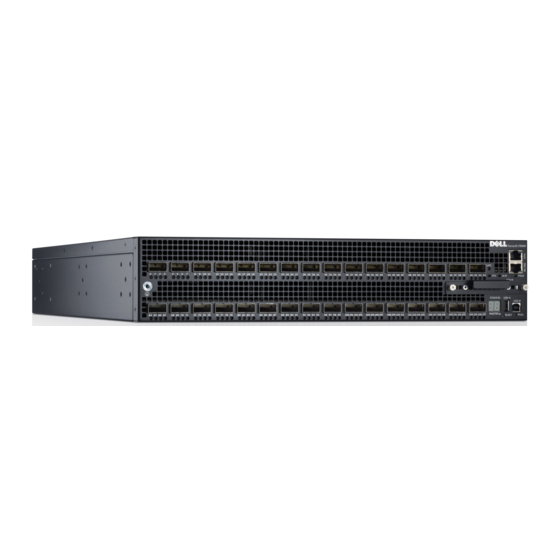
Data Center cores. It is a 2-rack unit (RU) chassis that supports 32 ports of 40GE QSFP+ or 128 ports of 10GE SFP+ (with breakout cables). The Z9000 includes an RS-232 console port and a management port for system access. As shown in Figure 2-1, the Z9000’s I/O (Input/... -
Page 8: Orderable Z9000 Components
Orderable Z9000 components The Z9000 can be ordered in several different configurations. Optional modules and optics are ordered separately. Table 2-1. Supported Hardware Components Hardware Catalog Number Z9000-AC 32-port 40G QSFP+ ports, 1 AC power supply, 1 fan subsystem (airflow from I/O side to... -
Page 9: Features
• Spare optics • Breakout cable Features The Z9000 offers the following: • Z9000 CPU and switch processor • Hot swappable redundant power supplies • 19-inch rack-mountable • Standard 2U chassis height • Up to 128K MAC address entries supported with hardware assisted aging •... -
Page 10: System Status
FTOS Command Reference for the Z9000 and the FTOS Configuration Guide for the Z9000. LED displays As shown in figure below, the Z9000 includes LED displays on the I/O side of the chassis. When the Z9000 powers up, or reloads, the PSU LED is solid yellow. The system LEDs are:... - Page 11 Green — Link up at 1G speed Amber — Link up at 100M or 10Mspeed Off —No link Activity LED (left side of port) Blinking Green — Activity, transmitting or receiving packet at this port. Off —No traffic The Z9000 System...
- Page 12 The Z9000 System...
-
Page 13: Site Preparations
Site Preparations The Z9000 is suitable for installation as part of a Common Bond Network (CBN). It can be installed in • network telecommunication facilities • data centers • other locations where the National Electric Code (NEC) applies This chapter covers the following topics: •... -
Page 14: Cabinet Placement
Fans and airflow The Z9000 system fans support with 2 air flow options. Be sure to order the fans suitable to support your site’s proper ventilation. Use a single type of fan in your system. Do not mix Reverse and Normal fans in a single chassis. -
Page 15: Storing Components
WARNING: Electrostatic discharge (ESD) damage can occur when components are mishandled. Always wear an ESD-preventive wrist or heel ground strap when handling the Z9000 and its accessories. After you remove the original packaging, place the Z9000 and its components on an antistatic surface. - Page 16 Site Preparations...
-
Page 17: Install The Z9000
To install the Z9000 system, Dell Force10 recommends that you complete the installation procedures in the order presented below. Always handle the system and its components with care. Avoid dropping the Z9000 switch or its field replaceable units. Install the Z9000 chassis in a rack or cabinet... -
Page 18: Install Chassis Into Rack Or Cabinet
Follow the steps below to install a switch into a two-post 19-inch equipment rack, using the already attached mounting brackets. Step Task Dell Force10 recommends that one person hold the Z9000 chassis in place while another attaches the brackets to the posts. Install the Z9000... -
Page 19: Attach Ground Cable
Use a single M4x0.7 screw for attaching a ground cable to the chassis. The cable itself is not included. Dell Force10 recommends a 6AWG one-hole lug, #10 hole size, 63" spacing (not included in shipping) to properly ground the chassis. The one-hole lug must be a UL recognized, crimp-type lug. -
Page 20: Install The Qsfp+ Optics
Do not jerk or tug repeatedly on the tab. Splitting QSFP ports to SFP+ ports The Z9000 supports splitting a single 40G QSFP port into four 10G SFP+ ports using one of the supported breakout cables (refer to Table for a list of supported cables). -
Page 21: Install The Solid Date Drive
Install the Solid Date Drive The Z9000 includes a Solid State Drive (SSD) that acts as another storage device. The SSD is shipped installed with the Z9000 system, and is located in a slot on the lower-right area on the I/O side (Figure 2-1). -
Page 22: Supply Power And Power Up The System
AC power Connect the plug to each AC power connector, making sure that the power cord is secure. As soon as the cable is connected between the Z9000 and the power source, the chassis is powered-up; there is no on/off switch. -
Page 23: Hot-Swap Units In A Stack
Attach the connectors to the PSUs, making sure that the connections are secure. Replace the plastic cover over the DC connectors. As soon as the cable is connected between the Z9000 and the power source, the chassis is powered-up; there is no on/off switch. - Page 24 Install the Z9000...
-
Page 25: Power Supplies
NOTE: If using a single PSU, you must install a blank plate in the other PSU slot. Dell Force10 recommends using PSU0, if installing only one power supply. -
Page 26: Install A New Ac Power Supply
To install a new power supply, follow the steps below: The power supply modules should slide into the slots smoothly. Do not force a module into a slot. This may damage the power supply or the Z9000 chassis. Step Task Take the power supply unit out of the shipping box. -
Page 27: Replace A Power Supply
Chapter 9, Technical Support to request a hardware replacement. NOTE: If using a single PSU, you must install a blank plate in the other PSU slot. Dell Force10 recommends using PSU0, if installing only one power supply. Replace an AC power supply... - Page 28 Step Task Using the grab handle on the replacement unit, slide it into the power supply bay. Tighten the securing screw on the side of the PSU. Ensure that the module is secure. Replace the small plastic cover over the DC cable connectors. Attach the power cable to the new module.
-
Page 29: Fans
• Z9000 Fan module (Catalog# Z9000-FAN) • Z9000 Fan module - Reverse flow (Catalog# Z9000-FAN-R) Install a fan module The fan modules in the Z9000 are field replaceable. Module Slot 0 is on the left; Module Slot 3 is on the right. Fans... -
Page 30: Replace A Fan Module
Figure 6-1. Removing the fan module screen Fan modules PSU0 PSU1 Latching screw Latching screw Fan screen Figure 6-2. Replacing the fan module PSU0 Fan Module 0 Fan Module 1 Fan Module 2 Fan Module 3 Grab Handle PSU1 Screw To install a new fan module, follow the steps below: Step Task... - Page 31 Step Task Loosen the securing screw on the side of the unit. CAUTION: Steps 2-3 must be completed in within 1 minute, or the chassis will power down. Use the grab handle to slide the module out of the bay. Using the grab handle on the replacement module, slide it into the bay.
- Page 32 Fans...
-
Page 33: Access Ports
Step Task Install an RJ-45 copper cable into the console port. Use a rollover cable to connect the Z9000 console port to a terminal server. Connect the other end of the cable to the DTE terminal server. -
Page 34: Access The Rj-45 Console Port With A Db-9 Adapter
• 1 stop bit • No flow control When the USB-B port is connected, it becomes the primary connection and the system sends all messages to the USB-B drive when it is connected. Figure 7-2. Z9000 USB-B port connector USB-B Port Access ports... - Page 35 NOTE: Before starting this procedure, be sure you have a terminal emulation program already installed on your PC. You will also require appropriate drivers for the USB device in use. Contact Dell Force10 Networks Technical Support for assistance. Step Task...
-
Page 36: Access The Solid State Drive (Ssd)
Restart the system. Included here are some key commands, but not all of the commands supported by the SSD. Refer to the Z9000 Command Line Reference Guide for a complete discussion of the commands supported by the SSD. View files on the SSD Use the command to view files on the SSD. -
Page 37: Copy Files To And From The Ssd
drw- 8192 Mar 30 1919 10:31:04 TRACE_LOG_DIR drw- 8192 Mar 30 1919 10:31:04 CRASH_LOG_DIR drw- 8192 Mar 30 1919 10:31:04 NVTRACE_LOG_DIR drw- 8192 Mar 30 1919 10:31:04 CORE_DUMP_DIR d--- 8192 Mar 30 1919 10:31:04 ADMIN_DIR --More-- Copy files to and from the SSD Use the command to copy files to or from the SSD. - Page 38 Access ports...
-
Page 39: Z9000 Specifications
Z9000 Specifications This chapter contains these major sections: • Chassis Physical Design • Agency Compliance Chassis Physical Design Parameter Specifications Height 3.48 inches (8.8 cm) Width 17.32 inches (44.0 cm) Depth 24.00 inches (61.00 cm) Chassis weight with factory-installed xx lbs (approx.) (xx kg) -
Page 40: Dc Power Requirements
Properly shielded and grounded cables and connectors must be used in order to meet FCC emission limits. Dell Force10 Networks is not responsible for any radio or television interference caused by using other than recommended cables and connectors or by unauthorized changes or modifications in the equipment. - Page 41 This product is in conformity with the protection requirements of EU Council Directive 2004/108/EC on the approximation of the laws of the Member States relating to electromagnetic compatibility. Dell Force10 can not accept responsibility for any failure to satisfy the protection requirements resulting from a non-recommended modification of this product, including the fitting of non-Dell Force10 option cards.
- Page 42 WARNING: AC Power cords are for use with Dell Force10 Networks equipment only. Do not use Dell Force10 Networks AC power cords with any unauthorized hardware. Korean Certification of Compliance Korean Package Label Safety Standards and Compliance Agency Certifications • CUS UL 60950-1, 2nd Edition •...
- Page 43 Force10 Networks encourages owners of information technology (IT) equipment to responsibly recycle their equipment when it is no longer needed. Dell Force10 offers a variety of product return programs and services in several countries to assist equipment owners in recycling their IT products.
- Page 44 EEE on the environment and human health due to the potential presence of hazardous substances in EEE. Dell Force10 Networks products, which fall within the scope of the WEEE, are labeled with the crossed- out wheelie-bin symbol, as shown above, as required by WEEE.
- Page 45 Contact Dell Force10 Technical Support for assistance if the battery requires replacement. WARNING: Always wear an ESD-preventive wrist or heel ground strap when handling the Z9000 and its components. As with all electrical devices of this type, take all the necessary safety precautions to prevent injury when installing this system.
- Page 46 Customer participation is important to minimize any potential effects of batteries and accumulators on the environment and human health due to the potential presence of hazardous substances. For proper collection and treatment, contact your local Dell Force10 Networks representative. Figure 8-1. The European WEEE Symbol For California: Perchlorate Material —...
-
Page 47: Technical Support
Requesting a hardware replacement The iSupport website iSupport provides a range of documents and tools to assist you with effectively using Dell Force10 equipment and mitigating the impact of network outages. Through iSupport you can obtain technical information regarding Dell Force10 products, access to software upgrades and patches, and open and manage your Technical Assistance Center (TAC) cases. -
Page 48: Contacting The Technical Assistance Center
Contacting the Technical Assistance Center How to Contact Dell Force10 Log in to iSupport at http://www.force10networks.com/support/ and select the Service Request tab. Information to Submit When • Your name, company name, phone number, and E-mail address Opening a Support Case •... -
Page 49: Requesting A Hardware Replacement
• Using the Create Service Request form on the iSupport page (see Contacting the Technical Assistance Center). • Contacting Dell Force10 directly by E-mail or by phone (see Contacting the Technical Assistance Center). Provide the following information when using E-mail or phone: •... - Page 50 Technical Support...
- Page 52 Printed in the U.S.A. w w w . d e l l . c o m | s u p p o r t . d e l l . c o m...