Lenovo ThinkPad 10 Hardware Maintenance Manual
Hide thumbs
Also See for ThinkPad 10:
- User manual (110 pages) ,
- Hardware maintenance manual (60 pages) ,
- Safety, warranty, and setup manual (2 pages)
Table of Contents
Advertisement
Advertisement
Chapters
Table of Contents

Related Manuals for Lenovo ThinkPad 10


Summary of Contents for Lenovo ThinkPad 10
- Page 1 Hardware Maintenance Manual ThinkPad 10...
- Page 2 Appendix A “Notices” on page 75. First Edition (May 2014) © Copyright Lenovo 2014. LIMITED AND RESTRICTED RIGHTS NOTICE: If data or software is delivered pursuant a General Services Administration “GSA” contract, use, reproduction, or disclosure is subject to restrictions set forth in Contract No. GS-35F-05925.
-
Page 3: Table Of Contents
... . . 77 Chapter 5. Locations ..33 Locating tablet controls, connectors, and indicators....© Copyright Lenovo 2014... - Page 4 Hardware Maintenance Manual...
-
Page 5: About This Manual
• Before servicing a ThinkPad product, be sure to read all the information under Chapter 1 “Safety information” on page 1 and Chapter 2 “Important service information” on page 19. © Copyright Lenovo 2014... - Page 6 Hardware Maintenance Manual...
-
Page 7: Chapter 1. Safety Information
• After service, reinstall all safety shields, guards, labels, and ground wires. Replace any safety device that is worn or defective. • Reinstall other parts that you have removed. Electrical safety Observe the following rules when working on electrical equipment. Important: © Copyright Lenovo 2014... - Page 8 • Use only approved tools and test equipment. Some hand tools have handles covered with a soft material that does not insulate you when working with live electrical currents. • Many customers have, near their equipment, rubber floor mats that contain small conductive fibers to decrease electrostatic discharges.
-
Page 9: Safety Inspection Guide
Safety inspection guide The purpose of this inspection guide is to assist you in identifying potentially unsafe conditions. As each machine was designed and built, required safety items were installed to protect users and service technicians from injury. This guide addresses only those items. You should use good judgment to identify potential safety hazards due to attachment of non-ThinkPad features or options not covered by this inspection guide. -
Page 10: Grounding Requirements
1. Use product-specific ESD procedures when they exceed the requirements noted here. 2. Make sure that the ESD protective devices you use have been certified (ISO 9000) as fully effective. When handling ESD-sensitive parts: • Keep the parts in protective packages until they are inserted into the product. •... - Page 11 DANGER DANGER DANGER DANGER DANGER DANGER Chapter 1 Safety information...
- Page 12 DANGER Hardware Maintenance Manual...
- Page 13 PERIGO PERIGO Chapter 1 Safety information...
- Page 14 PERIGO PERIGO PERIGO PERIGO PERIGO PERIGO Hardware Maintenance Manual...
- Page 15 DANGER DANGER DANGER DANGER DANGER Chapter 1 Safety information...
- Page 16 DANGER DANGER DANGER VORSICHT VORSICHT Hardware Maintenance Manual...
- Page 17 VORSICHT VORSICHT VORSICHT VORSICHT Chapter 1 Safety information...
- Page 18 VORSICHT VORSICHT Hardware Maintenance Manual...
- Page 19 Chapter 1 Safety information...
- Page 20 Hardware Maintenance Manual...
- Page 21 Chapter 1 Safety information...
- Page 22 Hardware Maintenance Manual...
- Page 23 Chapter 1 Safety information...
- Page 24 Hardware Maintenance Manual...
-
Page 25: Chapter 2. Important Service Information
Lenovo Support Center are available at: http://www.lenovo.com/support/phone • Service training documents for Lenovo authorized service technicians are available at the following Web site. The disassembly and reassembly videos that show the FRU removal and replacement procedures are contained in the documents. -
Page 26: Strategy For Replacing Frus For Cto, Special Bid Model, And Standard Models
Dynamic Configure To Order (CTO) This model provides the ability for a customer to configure a Lenovo solution from a web site, and have this configuration sent to fulfillment, where it is built and shipped directly to the customer. The machine label and eSupport will load these products as the 4-character MT, 4-character model and 2-character country code. - Page 27 4. Tap Product and Parts Detail. 5. On the PRODUCT AND PARTS DETAIL page, tap Parts Detail tab to view the FRU list. Note: The FRU list is a general list of components and does not contain specific model information. Chapter 2 Important service information...
- Page 28 Hardware Maintenance Manual...
-
Page 29: Chapter 3. General Checkout
• Damage caused by liquid spilled into the system • Damage caused by the improper insertion of a PC Card or the installation of an incompatible card • Fuses blown by attachment of a nonsupported device © Copyright Lenovo 2014... -
Page 30: Checkout Guide
This computer supports only batteries specially designed for this specific system and manufactured by Lenovo or an authorized builder. The system does not support unauthorized batteries or batteries designed for other systems. If an unauthorized battery or a battery designed for another systems is installed, the system will not charge. -
Page 31: Checking The Ac Power Adapter
3. Clear Complementary Metal Oxide Semiconductor (CMOS) by inserting a straightened paper clip into the emergency reset hole and pressing the Windows button at the same time. 4. Press the power button. If the tablet cannot be turned on, continue with the next step. 5. - Page 32 Hardware Maintenance Manual...
-
Page 33: Chapter 4. Related Service Information
2. In the Remove everything and reinstall Windows section, tap Get started. Then tap Next to confirm the operation. 3. Depending on your needs, do one of the following: • To perform a quick format, tap Just remove my files to start the process. The process will take several minutes. © Copyright Lenovo 2014... -
Page 34: Using The Advanced Startup Options
• To perform a complete format, tap Fully clean the drive to start the process. The process will take several hours. 4. Follow the instructions on the screen to reset your tablet to the factory default settings. Using the advanced startup options With the advanced startup options, you can change the firmware settings of the tablet, change the startup settings of the Windows operating system, start the tablet from an external device, or restore the Windows operating system from a system image. -
Page 35: Supervisor Password
Important: If you clear the Copy the recovery partition from the PC to the recovery drive. option, you will create recovery media without the recovery partition content. You still can start the tablet from the recovery media, but you might be unable to recover your tablet if the recovery partition on your tablet is damaged. -
Page 36: Symptom-To-Fru Index
Lenovo cannot reset your password. You must take your computer to a Lenovo reseller or a Lenovo marketing representative to have the system board replaced. Proof of purchase is required, and a fee will be charged for parts and service. -
Page 37: Numeric Error Codes
Note: For a device not supported by diagnostic codes in the ThinkPad tablet computers, see the manual for that device. Numeric error codes Table 1. Numeric error codes Symptom or error FRU or action, in sequence 0183 Checksum of the Security settings in the EFI Variable Bad CRC of Security Settings in EFI Variable. -
Page 38: Undetermined Problems
Undetermined problems If the diagnostic tests did not identify the adapter or device that has failed, if wrong devices are installed, or if the system simply is not operating, follow these procedures to isolate the failing FRU (do not isolate FRUs that have no defects). -
Page 39: Chapter 5. Locations
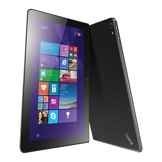
Screen-rotation-lock button Power button Combo audio connector Volume-control buttons Emergency-reset hole NFC touchpoint (on some models) Micro-SIM-card slot Micro-SD-card slot Micro HDMI connector Keyboard connector Windows Start-screen control Dock connector Multi-touch screen Power connector USB 2.0 connector © Copyright Lenovo 2014... -
Page 40: Locating Frus And Crus
CRUs, you can either install the CRU yourself or you can request that a Service Provider install the CRU according to the warranty service for your product. If you intend on installing the CRU, Lenovo will ship the CRU to you. CRU information and replacement instructions are shipped with your product and are available from Lenovo at any time upon request. -
Page 41: Major Frus
Major FRUs Self-service CRU Optional-service CRU LCD module GPS-antenna cable Wireless-LAN antenna assembly NFC-antenna cable Front-facing camera Chapter 5 Locations... -
Page 42: Miscellaneous Kits And Other Parts
Self-service CRU Optional-service CRU Camera card NFC cable NFC card Wireless WAN card System board Rear-facing camera Fingerprint-reader card Speakers assembly DC-in-card-with-USB-connector cable Back cover assembly Smart-card-reader cable Smart card reader Touch-sensor cable Docking-support-card cable Digitizer cable Docking-support card Built-in battery DC-in card with USB connector Camera-card cable Wireless-LAN antenna assembly... -
Page 43: Looking Up Fru Information
Looking up FRU information For detailed FRU information, including part numbers, descriptions, and substitution part numbers, go to http://www.lenovo.com/serviceparts-lookup. Chapter 5 Locations... - Page 44 Hardware Maintenance Manual...
-
Page 45: Chapter 6. Fru Replacement Notices
Lenovo will ship the CRU to you. CRU information and replacement instructions are shipped with your product and are available from Lenovo at any time upon request. You can find a list of CRUs for your product in this Hardware Maintenance Manual. An electronic version of this manual can be found at http://www.lenovo.com/support. -
Page 46: Retaining Serial Numbers
• Ensure that torque screwdrivers are calibrated correctly following country specifications. Retaining serial numbers Instructions for retaining serial numbers, MTM, UUID, or asset ID can be found from the Lenovo Support Web site at: http://www.lenovo.com/support Hardware Maintenance Manual... -
Page 47: Chapter 7. Removing Or Replacing A Fru
Lenovo will ship the CRU to you. CRU information and replacement instructions are shipped with your product and are available from Lenovo at any time upon request. You can find a list of CRUs for your product in this Hardware Maintenance Manual. An electronic version of this manual is available for downloading at http://www.lenovo.com/support. -
Page 48: Before Servicing The Tablet
Before servicing the tablet Disabling the built-in battery Before replacing any FRU, ensure that you have disabled the built-in battery. To disable the built-in battery, press the emergency-reset button in the emergency-reset hole using a straightened paper clip. Removing the SIM card If the tablet you are servicing has a SIM card installed, remove the SIM card before servicing. -
Page 49: Removing The Sd Card
Removing the SD card If the tablet you are servicing has an SD card installed, remove the SD card before servicing. To remove the SD card, disable the built-in battery first. Chapter 7 Removing or replacing a FRU... -
Page 50: Removing Smart Card
Removing the smart card Some models are equipped with a smart card reader on the back cover. If the tablet you are servicing has a smart card installed in the smart card reader, remove the smart card before servicing. To remove the smart card, disable the built-in battery first. 1010 Back cover assembly and smart card reader This topic contains two parts: •... - Page 51 Release other hooks in numerical order as shown by using the hook-releasing tool. Note: Do not insert the hook-releasing tool into the hook hole area of the USB door as shown. Otherwise, the hook will be deformed. Release the right-bottom side of the back cover assembly first, and then release the left-bottom side. Chapter 7 Removing or replacing a FRU...
- Page 52 Lift up the upper-right corner of the back cover assembly, and then slide the back cover assembly to the left-upper corner to release the back cover assembly. Disconnect the cable. Note: Do not close the connector flip before inserting the cable. Hardware Maintenance Manual...
- Page 53 Locate the smart card reader installed on the back cover assembly. Remove the four screws that secure the smart card reader and then remove the smart card reader. Step Screw (quantity) Color Torque M1.6 × 3.5 mm, flat-head, nylon-coated (4) Silver 0.098 Nm (1.00 kgf-cm)
- Page 54 Detach the built-in battery connector. Note: Before removing any further FRU, ensure that the built-in battery connector is detached. When installing: Ensure that the connectors are attached firmly. For models that are not equipped with a smart card reader: Removal steps of the back cover assembly Release the hooks around the dock connector gently using your fingers.
- Page 55 Release other hooks in numerical order as shown by using the hook-releasing tool. Note: Do not insert the hook-releasing tool into the hook hole area of the USB door as shown. Otherwise, the hook will be deformed. Release the right-bottom side of the back cover assembly first, and then release the left-bottom side. Chapter 7 Removing or replacing a FRU...
- Page 56 Lift up the upper-right corner of the back cover assembly, and then slide the back cover assembly to the left-upper corner to release the back cover assembly. Detach the built-in battery connector. Note: Before removing any further FRU, ensure that the built-in battery connector is detached. Hardware Maintenance Manual...
-
Page 57: Applying Labels To Back Cover Assembly
Applying labels to the back cover assembly: The new back cover assembly is shipped with a kit containing labels of several kinds. Apply those labels when you replace the back cover assembly. For the labels that are not shipped with the new back cover assembly, peel them off from the old back cover assembly, and then adhere them to the new one. -
Page 58: 1020 Rear-Facing Camera
1020 Rear-facing camera For access, remove this FRU: • “1010 Back cover assembly and smart card reader” on page 44 Removal steps of the rear-facing camera When installing: Ensure that the connector is attached firmly. 1030 Fingerprint-reader card For access, remove this FRU: •... -
Page 59: 1040 Touch-Sensor Cable
Step Screw (quantity) Color Torque 0.098 Nm M1.6 × 3.5 mm, flat-head, nylon-coated (1) Silver (1.00 kgf-cm) When installing: Ensure that the connector is attached firmly. 1040 Touch-sensor cable For access, remove this FRU: • “1010 Back cover assembly and smart card reader” on page 44 Chapter 7 Removing or replacing a FRU... -
Page 60: 1050 Docking-Support-Card Cable
Removal steps of the touch-sensor cable Note: Do not close the connector flips before inserting the cable. When installing: Ensure that the connectors are attached firmly. 1050 Docking-support-card cable For access, remove this FRU: • “1010 Back cover assembly and smart card reader” on page 44 •... -
Page 61: 1070 Docking-Support Card
Removal steps of the digitizer cable Note: Do not close the connector flips before inserting the cable. When installing: Ensure that the connectors are attached firmly. 1070 Docking-support card For access, remove this FRU: • “1010 Back cover assembly and smart card reader” on page 44 •... -
Page 62: 1090 Camera-Card Cable
Removal steps of the wireless WAN card Note: The wireless WAN card is only available on some models. In step , unplug the connectors by using the antenna RF connector removal tool or pick up the connectors with your fingers and gently unplug them as shown. When installing: Plug the red cable into the main connector, and the blue cable into the auxiliary connector on the card. -
Page 63: 1100 Camera Card And Front-Facing Camera
Removal steps of the camera-card cable When installing: Ensure that the connectors are attached firmly. 1100 Camera card and front-facing camera For access, remove this FRU: • “1010 Back cover assembly and smart card reader” on page 44 Chapter 7 Removing or replacing a FRU... -
Page 64: 1110 Built-In Battery
• “1090 Camera-card cable” on page 56 Removal steps of the camera card and front-facing camera Step Screw (quantity) Color Torque 0.098 Nm M1.6 × 3.5 mm, flat-head, nylon-coated (1) Silver (1.00 kgf-cm) Detach the connector, and then turn over the camera card. Note: Do not close the connector flip before inserting the cable. -
Page 65: 1120 Dc-In Card With Usb Connector
Removal steps of the built-in battery Torque Step Screw (quantity) Color M1.6 × 2.0 mm, flat-head, nylon-coated (3) Black 0.098 Nm (1.00 kgf-cm) When installing: Ensure that the built-in battery cable is not twisted and not subject to any tension. 1120 DC-in card with USB connector For access, remove this FRU: •... -
Page 66: 1130 Speakers Assembly
Step Screw (quantity) Color Torque Black 0.098 Nm M1.6 × 4.0 mm, flat-head, nylon-coated (2) (1.00 kgf-cm) When installing: Ensure that the connector is attached firmly. 1130 Speakers assembly For access, remove these FRUs in order: • “1010 Back cover assembly and smart card reader” on page 44 •... -
Page 67: Step Screw (Quantity)
Step Screw (quantity) Color Torque M1.6 × 3.5 mm, flat-head, nylon-coated (2) Silver 0.098 Nm (1.00 kgf-cm) Cable routing: When you install the speakers assembly, route the cable as shown in the following illustration. Ensure that the cable is not twisted and not subject to any tension. Tension could cause the cable to be damaged by the cable guides, or a wire to be broken. -
Page 68: 1140 Nfc Card And Nfc Cable
1140 NFC card and NFC cable For access, remove this FRU: • “1010 Back cover assembly and smart card reader” on page 44 • “1090 Camera-card cable” on page 56 Removal steps of the NFC card and NFC cable Note: The NFC card and NFC cable are only available on some models. Note: Do not close the connector flips before inserting the cable. -
Page 69: 1150 System Board
When installing: Ensure that the connectors are attached firmly. 1150 System board For access, remove these FRUs in order: • “1010 Back cover assembly and smart card reader” on page 44 • “1030 Fingerprint-reader card” on page 52 • “1080 Wireless WAN card ” on page 55 •... -
Page 70: Color Torque
For models that are equipped with a fingerprint reader Step Screw (quantity) Color Torque M1.6 × 3.5 mm, flat-head, nylon-coated (2) Silver 0.098 Nm (1.00 kgf-cm) M1.6 × 2.0 mm, flat-head, nylon-coated (3) Black 0.098 Nm (1.00 kgf-cm) M1.6 × 4.0 mm, flat-head, nylon-coated (1) Black 0.098 Nm (1.00 kgf-cm) - Page 71 Step Screw (quantity) Color Torque 0.098 Nm M1.6 × 3.5 mm, flat-head, nylon-coated (3) Silver (1.00 kgf-cm) M1.6 × 2.0 mm, flat-head, nylon-coated (3) Black 0.098 Nm (1.00 kgf-cm) M1.6 × 4.0 mm, flat-head, nylon-coated (1) Black 0.098 Nm (1.00 kgf-cm) Step Screw (quantity) Color...
-
Page 72: 1160 Nfc-Antenna Cable
When installing: Ensure that the connectors are attached firmly. If the system board is replaced with a new one, after installing all other parts, you need to initialize the settings on the new system board. To initialize the settings on the new system board, do the following: 1. -
Page 73: 1170 Gps-Antenna Cable
1170 GPS-antenna cable For access, remove these FRUs in order: • “1010 Back cover assembly and smart card reader” on page 44 • “1040 Touch-sensor cable” on page 53 • “1050 Docking-support-card cable” on page 54 • “1080 Wireless WAN card ” on page 55 •... -
Page 74: 1180 Wireless-Wan Antenna Assembly
Cable routing: When you install the antenna assembly, route the cables as shown in the following illustration. Ensure that the cables do not get in contact with the system board and are not subject to any tension. Tension could cause the cables to be damaged by the cable guides, or a wire to be broken. When installing: Ensure that the connector is attached firmly. - Page 75 Cable routing: When you install the antenna assembly, route the cables as shown in one of the following illustrations. Ensure that the cables are not twisted and not subject to any tension. Tension could cause the cables to be damaged by the cable guides, or a wire to be broken. Note: Depending on the wireless WAN card installed, the wireless-WAN-antenna cable routing might be different as shown in the following illustrations.
-
Page 76: 1190 Wireless-Lan Antenna Assembly
• For the wireless WAN module: ME906C Wireless-WAN antenna (Main) Wireless-WAN antenna (Auxiliary) Main connector for the wireless WAN antenna cable Auxiliary connector for the wireless WAN antenna cable When installing: Ensure that the connectors are attached firmly. 1190 Wireless-LAN antenna assembly For access, remove these FRUs in order: •... - Page 77 Removal steps of the wireless-LAN antenna assembly Cable routing: When you install the antenna assembly, route the cables as shown in the following illustration. Ensure that the cables are not twisted and not subject to any tension. Tension could cause the cables to be damaged by the cable guides, or a wire to be broken.
-
Page 78: 1200 Base Bracket
Wireless-LAN antenna (Main) Wireless-LAN antenna (Auxiliary) When installing: Ensure that the connectors are attached firmly. 1200 Base bracket For access, remove this FRU: • “1010 Back cover assembly and smart card reader” on page 44 • “1020 Rear-facing camera” on page 52 •... -
Page 79: 1210 Dc-In-Card-With-Usb-Connector Cable And Lcd Module
Step Screw (quantity) Color Torque Black 0.098 Nm M1.6 × 2.0 mm, flat-head, nylon-coated (1) (1.00 kgf-cm) 1210 DC-in-card-with-USB-connector cable and LCD module For access, remove this FRU: • “1010 Back cover assembly and smart card reader” on page 44 •... - Page 80 Removal steps of the DC-in-card-with-USB-connector cable and LCD module When installing: • Ensure that the connector is attached firmly. • Ensure that the cable does not get in contact with the system board. Hardware Maintenance Manual...
-
Page 81: Appendix A. Notices
Lenovo representative for information on the products and services currently available in your area. Any reference to a Lenovo product, program, or service is not intended to state or imply that only that Lenovo product, program, or service may be used. Any functionally equivalent product, program, or service that does not infringe any Lenovo intellectual property right may be used instead. -
Page 82: Electronic Emission Notices
For electronic emission information on Class B digital devices, refer to the corresponding information in the User Guide. Trademarks The following terms are trademarks of Lenovo in the United States, other countries or both: Lenovo ThinkPad Microsoft and Windows are trademarks of the Microsoft group of companies. -
Page 83: Appendix B. Abbreviation And Acronym Table
ICCID integrate circuit card identity International Standardization Organization local area network liquid crystal display media access control machine type machine type and model personal computer Platform Controller Hub POST power-on self-test random-access memory © Copyright Lenovo 2014... - Page 84 Abbreviation Term radio frequency RFID radio-frequency identification ring indicator registered jack SATA Serial Advanced Technology Attachment subscriber identity module supervisor password TFTs thin-film transistors UEFI Unified Extensible Firmware Interface Universal Serial Bus UUID universally unique identifier video graphics array VRAM video random-access memory Hardware Maintenance Manual...
- Page 86 Part Number: SP40A26965 Printed in China (1P) P/N: SP40A26965 *1PSP40A26965*...