Table of Contents
Advertisement
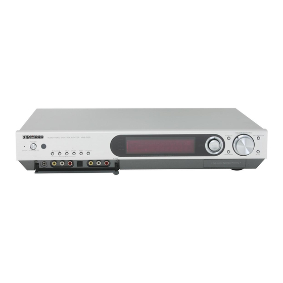
AUDIO VIDEO SURROUND RECEIVER
VRS - 7100
INSTRUCTION MANUAL
KENWOOD CORPORATION
Quick Start Reference
Please read the following pages so that you can enjoy the surround sound at the best
condition.
(These pages give shortcut explanations on how to connect the speaker system to the
receiver, set up the speakers and play a source.)
"Let's play DVD video software" )¡, ™£
About the supplied remote control
Compared to standard remote controls, the remote control supplied with this receiver has
several operation modes. These modes enable the remote control to control other audio/video
components. In order to effectively use the remote control it is important to read the operating
instructions and obtain a proper understanding of the remote control and how to switch its
operation modes (etc.).
Using the remote control without completely understanding its design and how to switch the
operation modes may result in incorrect operations.
B60-5462-10 02 MA ( K, P, E, X )
0312
Advertisement
Table of Contents

Related Manuals for Kenwood VRS-7100


Summary of Contents for Kenwood VRS-7100
-
Page 1: Instruction Manual
AUDIO VIDEO SURROUND RECEIVER VRS - 7100 INSTRUCTION MANUAL KENWOOD CORPORATION Quick Start Reference Please read the following pages so that you can enjoy the surround sound at the best condition. (These pages give shortcut explanations on how to connect the speaker system to the receiver, set up the speakers and play a source.) -
Page 2: Before Applying Power
Before applying power Caution : Read this page carefully to ensure safe operation. Units are designed for operation as follows. U.S.A. and Canada ... AC 120 V only Australia ... AC 240 V only Safety precautions WARNING : TO PREVENT FIRE OR ELECTRIC SHOCK, DO NOT EXPOSE THIS APPLIANCE TO RAIN OR MOISTURE. -
Page 3: How To Use This Manual
If any accessories are missing, or if the unit is damaged or fails to operate, notify your dealer immediately. If the unit was shipped to you directly, notify your shipper immediately. Kenwood recommends that you retain the original carton and packing materials in case you need to move or ship the unit in the future. -
Page 4: Special Features
Before applying the power Special features True home theater sound ‡ ~ · This receiver incorporates a wide variety of surround modes to bring you maximum enjoyment from your video software. Select a surround mode according to your equipment or the software you are going to play and enjoy! ÷... -
Page 5: Table Of Contents
Before applying the power Contents Caution : Read the pages marked Before applying power ... 2 Safety precautions ... 2 How to use this manual ... 3 Unpacking ... 3 Special features ... 4 Contents ... 5 Names and functions of parts ... 6 Main unit ... -
Page 6: Names And Functions Of Parts
Names and functions of parts Main unit Input mode indicators CLIP indicator Speaker selection indicators, Input channel indicators (The Input channel indicators lights up to indicate the channels contained in the input signal. The "S" indicator lights when the surround component consists of a single channel.) For Europe and Australia View when the GAME/ FRONT AUX jack... -
Page 7: Remote Control Unit
Names and functions of parts Remote control unit This remote control unit can be use not only for Kenwood products but also for other non-Kenwood products by setting the appropriate manufacturer’s setup codes. u For the U.S.A., Canada and Australia: RC-R0730... -
Page 8: Setting Up The System
Setting up the system CAUTION Make sure that the power cord plug is disconnected from the AC wall outlet before proceeding to connections. Also be sure to disconnect the power cord plug from the AC wall outlet before changing connections. For the connections of other system components, see pages 9 to 18. -
Page 9: Connecting A Dvd Player
Setting up the system Connecting a DVD player If you have connected a DVD player to the receiver with digital connection,be sure to read the "Input mode settings", "Re-assignment of rear panel jacks" section carefully. 8• For U.S.A. and Canada Monitor TV COMPONENT VIDEO IN... -
Page 10: Connecting Video Components, Audio Components
Setting up the system Connecting video components, audio components For U.S.A. and Canada Audio components AUDIO LINE OUT (Audio cord) Monitor TV MONITOR VIDEO IN (Yellow RCA pin cords) VIDEO IN VIDEO OUT VIDEO IN VIDEO IN PLAY IN REC OUT PLAY IN PLAY IN REC OUT PLAY IN VIDEO 2 VIDEO 1... - Page 11 Setting up the system For Europe and Australia Audio components AUDIO LINE OUT (Audio cord) Monitor TV MONITOR VIDEO IN (Yellow RCA pin cords) VIDEO IN VIDEO OUT VIDEO IN PLAY IN REC OUT PLAY IN VIDEO 2 VIDEO 1 VIDEO (Yellow RCA pin...
-
Page 12: Digital Connections
Setting up the system Digital connections The digital in jacks can accept DTS,Dolby Digital,or PCM signals.Connect components capable of outputting DTS,Dolby Digital or PCM (CD) digital signals. If you have connected a DVD player to the receiver with digital connection,be sure to read the "Input mode settings", "Re-assignment of rear panel jacks"... -
Page 13: Connecting The Speakers
Setting up the system Connecting the speakers For U.S.A. and Canada CAUTION Make sure that the power cord plug is disconnected from the AC wall outlet before proceeding to speaker cord connections. If the conductor wires on the extremity of speaker cord are untwisted, there is a risk of short-circuiting. -
Page 14: Protection Circuitry
Setting up the system For Europe and Australia CAUTION Make sure that the power cord plug is disconnected from the AC wall outlet before proceeding to speaker cord connections. If the conductor wires on the extremity of speaker cord are untwisted, there is a risk of short-circuiting. -
Page 15: Connecting The Speaker Terminals
Setting up the system Connecting the speaker terminals For U.S.A. and Canada 1 Strip coating. 3 Insert the cord. Twist 4 Return the lever. 2 Push the lever. For Europe and Australia 1 Strip coating. 3 Insert. Twist 2 Loosen. 4 Secure. -
Page 16: Pre Out Connections
Setting up the system PRE OUT connections The receiver has additional PRE OUT jacks. Note that the output from the PRE OUT jacks needs to be connected to an external power amplifier. If you want to connect surround back speakers to these jacks, be always sure to connect two surround back speakers for the left and right. -
Page 17: Connecting To The Game Jacks / Front Aux Jacks
Setting up the system Connecting to the GAME jacks / FRONT AUX jacks If you use a component that you do not usually connect to the receiver, such as a portable video camera, connect it to the GAME or FRONT AUX jacks on the front panel of the receiver. -
Page 18: Connecting The Antennas
Setting up the system Connecting the antennas AM loop antenna The supplied loop antenna is for use indoors. Place it as far as possible from the receiver, TV set, speaker cords and power cord, and adjust the direction for best reception. AM antenna terminal connections 1 Push lever. -
Page 19: Preparing The Remote Control
Setting up the system Preparing the remote control Loading the batteries 1 Remove the cover. 2 Insert the batteries. 3 Close the cover. ¶ Insert two AA-size (R6) batteries as indicated by the polar- ity markings. Remote control operation When the STANDBY indicator is lit, the power turns ON when you press the POWER RCVR on the remote control. -
Page 20: Let's Play Dvd Video Software (For U.s.a. And Canada)
Let’s play DVD video software STEP 1 Connect the speakers and TV to the receiver. For details, see "Setting up the system" 8 ~ & CAUTION Make sure that the power cord plug is disconnected from the AC wall outlet before proceeding to speaker cord connections. If the conductor wires on the extremity of speaker cord are untwisted, there is a risk of short-circuiting. - Page 21 POWER ON/STANDBY INPUT SELECTOR MULTI CONTROL %/fi/@/# ENTER If you connect KENWOOD speaker system KS-2100HT, KS-3100EX, KS-708HT, KS-308HT, KS-708HT+KS-308EX, KS-308HT+ KS-308EX, KS-908HT or KS-908EX: Press to select the model of the connected speaker system and press "HTB1 6.1CH": Speaker system KS-3100EX.
-
Page 22: Let's Play Dvd Video Software
Let’s play DVD video software STEP 1 Connect the speakers and TV to the receiver. For details, see "Setting up the system" 8 ~ & CAUTION Make sure that the power cord plug is disconnected from the AC wall outlet before proceeding to speaker cord connections. If the conductor wires on the extremity of speaker cord are untwisted, there is a risk of short-circuiting. - Page 23 ON/STANDBY INPUT SELECTOR MULTI CONTROL %/fi/@/# ENTER If you connect KENWOOD speaker system KS-2100HT, KS-3100EX, KS-708HT, KS-308HT, KS-708HT+KS-308EX, KS-308HT+ KS-308EX, KS-908HT or KS-908EX: Press to select the model of the connected speaker system and press "HTB1 6.1CH": Speaker system KS-3100EX.
-
Page 24: Preparing For Playback
(or the Enter key) again to establish the setup. ÷ Select "CANCEL" to return to the status before setup. ÷ When you use a KENWOOD speaker system and select "HTB1 6.1CH", "HTB1 5.1CH", "HTB2 6.1CH", "HTB2 5.1CH", "HTB3 6.1CH" or "HTB3 5.1CH" set the speaker setup, the audio will be corrected automatically according to the speaker characteristics. - Page 25 Preparing for playback Select a speaker system. 1 Use the MULTI CONTROL % / fi (or the Multi % / fi keys) to select the appropriate subwoofer setting. 1 "SUBW ON" : When a subwoofer is connected. 2 "SUBW OFF" : When no subwoofer is connected.
- Page 26 Preparing for playback ! Use the MULTI CONTROL % / fi (or the Multi % / fi keys) to select the appropriate BS/SW amp setting. 1 "BS/SW BS": Select this setting when a surround back speaker is connected to the SURR BACK/SW terminals. In this case, the subwoofer signal will be output from the PRE OUT SUBWOOFER jack.
- Page 27 Preparing for playback Input the distance to the speakers. This setting allows the signals output from different speakers to reach the listening position simultaneously. Measure the distance from the listening position to each of the speakers. Jot down the distance to each of the speakers. Distance to Front speaker (L) Distance to Center speaker (C) Distance to Front speaker (R)
-
Page 28: Re-Assignment Of Rear Panel Jacks
Preparing for playback Input level adjustment (analog sources only) If the input level of an analog source signal is too high, the "CLIP" indicator will lights up to indicate the source signal. Adjust the input level. 1 Press the RCV Mode key on the remote control unit to set it to the receiver control mode. -
Page 29: Normal Playback
Normal playback Some preparatory steps are needed before starting playback. POWER ON/STANDBY ON/STANDBY INPUT SELECTOR RCV Mode POWER RCVR Input Mode Turning on the receiver 1 Turn on the power to the related components. 2 Turn on the power to this receiver by pressing the POWER ON/STANDBY or ON/STANDBY POWER RCVR key). -
Page 30: Listening With Headphones
Normal playback Listening with headphones DUAL SOURCE VOLUME 5/∞ DUAL SOURCE INPUT VOLUME CONTROL PHONES DUAL SOURCE ON/OFF 1 Connect headphones to the PHONES jack. 2 Use the VOLUME CONTROL knob (or the VOL +/– keys) to adjust the volume. Playing difference sources through speakers and headphones (DUAL SOURCE function) While you enjoy audio listening through the speakers, another person... - Page 31 Normal playback ACTIVE EQ mode You can enjoy a more impressive sound effect when ACTIVE EQ is turned ON. Press the ACTIVE EQ key (or the Active EQ key) for the following selections: 1 "EQ MUSIC " : (The "ACTIVE EQ" indicator lights up) Effective when listening to music.
-
Page 32: Recording
Recording Analog sources INPUT SELECTOR 1 Use the INPUT SELECTOR key (or the input selector key) to select the source (other than "VIDEO 1") you want to record. 2 Put the component connected to the VIDEO 1 jacks to the record-pause mode. -
Page 33: Listening To Radio Broadcasts
Listening to radio broadcasts The receiver can store up to 40 stations in the memory and recall them by one-touch operation.Radio stations can be classified into RDS (Radio Data System) stations and other stations. To listen to or store RDS stations in the preset memory see "Using RDS (Radio Data System) (For Europe)". Tuning (non-RDS) radio stations BAND AUTO/MONO... -
Page 34: Receiving Preset Stations
Listening to radio broadcasts Receiving preset stations INPUT SELECTOR TUNER Numeric keys Use the INPUT SELECTOR key (or the TUNER key) to select tune as the source. Enter the number of the preset station you want to receive (up to "40"). Press the numeric keys in the following order: For "15", press 0,5 For "20", press 0,0,) -
Page 35: Using Rds (Radio Data System)
Using RDS (Radio Data System) RDS is a system that transmits useful information (in the form of digital data) for FM broadcasts along with the broadcast signal. Tuners and receivers designed for RDS reception can extract the information from the broadcast signal for use with various func- tions, such as automatic display of the station name. -
Page 36: Tuning By Program Type
Using RDS (Radio Data System) (For Europe only) Presetting RDS stations (RDS AUTO MEMORY) This function automatically stores up to 40 RDS stations in the preset memory. In order to use the PTY function, the RDS stations must be stored in the preset memory using the RDS Auto Memory function. Use the INPUT SELECTOR key (or the TUNER key) to select tune as the source. -
Page 37: Ambience Effects
Front Speakers. However, in order to enjoy the benefit of true 6.1 channel Dolby Digital Surround EX sound, KENWOOD recommends that you connect a full set of speakers. Dolby PRO LOGIC II x/ Dolby PRO LOGIC II... - Page 38 Ambience effects DTS-ES The DTS-ES (Digital Theater System-Extended Surround) represents 6.1-channel Discrete Surround format, expanding upon 5.1 surround. DTS-ES format is a 6.1 channel sound system for movie theaters that includes an additional surround center channel matrixed within sur- round left and surround right. It’s compatible on predecessor DTS 5.1 system.
-
Page 39: Virtual Modes
Ambience effects Dolby Virtual Speaker The Dolby Virtual Speaker features a virtual surround sound field. This implements an effect as if there are multiple speakers in the listening room. Dolby Headphone When headphones are used in music listening, the audio of the left (or right) channel reaches only the left (or right) year so the listener cannot feel the presence of acoustic images on the front. -
Page 40: Surround Play
Ambience effects Surround play The desired listen mode can be selected according to the input signal. Input Mode Listen Mode5/ ∞ Preparations ÷ Turn ON related components. ÷ Complete "Preparing for playback" (speaker settings). ¢ ÷ Use the INPUT SELECTOR key (or Input Selector keys) to select the component you wish to play back with surround sound. - Page 41 Ambience effects Listen modes available with analog or PCM playback: Main example of medium: Digital sources including DVD 96 kHz linear PCM and CD. Analog source such as VCR or radio broadcasting. 1 "PL IIx MOVIE": DOLBY PRO LOGIC IIx surround MOVIE mode *1 2 "PL IIx MUSIC": DOLBY PRO LOGIC IIx surround MUSIC mode *1 *2 3 "PL IIx GAME":...
-
Page 42: Convenient Functions
Convenient functions You can make further adjustments to the sound while listening to playback in the surround mode. ÷ The mode using Sound key is defeated when the REC MODE is ON. ¤ MULTI CONTROL % / fi / @ / # ENTER RCV Mode Dimmer... - Page 43 Convenient functions Switching between main audio and sub audio (DOLBY DIGITAL mode only) When listening to audio multiplex broadcasting such as two-language satellite digital broadcasting, the main and sub audio can be switched over. 1 Press the RCV Mode key on the remote control unit to set it to the receiver control mode.
- Page 44 Convenient functions Center Image mode (Only when the input signal is a 2-channel signal in the DTS NEO:6 MUSIC mode.) In the CENTER IMAGE setting mode of the NEO:6 MUSIC listen mode, it is possible to enhance the center channel audio by adjusting the center signal component.
-
Page 45: Basic Remote Control Operations For Other Components
Refer to the setup code lists to find the setup code for the component to be registered. uQ Example: To register a DVD made by KENWOOD, you would enter "0490" or "0534". Press the input selector key (DVD, VID1, VID2, AUX, F.AUX or Game) you want to register a system component. -
Page 46: Checking The Codes
Basic remote control operations for other components Checking the codes The 4-digit setup codes registered in the input selector keys can be checked as follows. Press the input selector key in which the setup code of the desired component is registered. Press and hold the Remote Setup key until the LED blinks twice, then release the Remote Setup key. -
Page 47: Setup Code Chart (Rc-R0730) (For U.s.a., Canada And Australia)
Even when a component is manufactured by a maker listed in the setup code chart, it may be unable to be registered depending on the model and year of production. Also, when a setup code of a non-KENWOOD maker is registered, certain component models may be unable to be controlled or only the limited functions may be controllable. - Page 48 Hyundai 0849 Infinity 0054 Inteq 0017 TV (Continued) Maker Setup codes 0054 0000 0053 0180 Kenwood 0030 0765 0180, 0030 0856 0047, 0054, 0154, 0156, 0178 Magnasonic 1928, 1913 Magnavox 0054, 0030, 1454, 0706, 1254, 1931, 1913 Marantz 0054, 0030...
- Page 49 Basic remote control operations for other components TV (Continued) Maker Setup codes Sheng Chia 0093 Sony 0000, 0834, 1925 Soundesign 0180, 0178 Squareview 0171 0180 Starlite 0180 Supreme 0000 0748 Sylvania 0054, 0030, 0171, 1944, 1931 Symphonic 0180, 0171, 1913 Tandy 0093 Technics...
- Page 50 Basic remote control operations for other components VCR (Continued) Maker Setup codes Kenwood 0067 Kodak 0035, 0037 0037 Magnavox 0035, 0039, 0081 Magnin 0240 Marantz 0035, 0081 Marta 0037 Matsushita 0035, 0162 0035 Memorex 0035, 0162, 0037, 0048, 0039, 0047, 0240, 0104...
-
Page 51: Setup Code Chart (Rc-R0730E) (For Europe)
Even when a component is manufactured by a maker listed in the setup code chart, it may be unable to be registered depending on the model and year of production. Also, when a setup code of a non-KENWOOD maker is registered, certain component models may be unable to be controlled or only the limited functions may be controllable. - Page 52 0157 Thorens 0157 Thule 0157 Toshiba 0692 Trio 0677 Universum 0157 Yamaha 0036 MD recorder Maker Setup codes Kenwood 1059, 0681, 1339 Satellite Receivers Maker Setup codes @sat 1300 @Sky 1334 ABsat 0123 Amstrad 0847, 0811, 0501 Arcon 1205 Aston...
- Page 53 Basic remote control operations for other components Satellite Receivers (Continued) Maker Setup codes Telestar 1100, 0501, 1202 Thomson 0853, 1046, 0265, 1291 Topfield 1207, 1206 0820, 1307 Triasat 0501 Triax 0115 Universum 0173, 0571 Ventana 0200 Vortec 0815 WinsTec 1240, 1241 Wisi 0173 Wisplus...
- Page 54 Basic remote control operations for other components TV (Continued) Maker Setup codes Hanimex 1908 Hanseatic 0556, 0037, 0361, 0320 Hantarex 0516 Havermy 0093 0412, 0282, 0009 Hinari 0037, 0218, 0036, 1908, 0009 Hisawa 0455, 0282 Hitachi 0548, 1037, 0036, 0225, 0105, 0217, 0356, 0578,0044, 0163, 0349, 0744, 1225, 0109, 0481, 0719, 1045...
- Page 55 Basic remote control operations for other components TV (Continued) Maker Setup codes Reoc 0714 Revox 0037 0264, 0206, 0163, 0259 0087 Roadstar 0264, 0218, 0009, 0418 Saba 0109, 0087, 0335, 0163 Saccs 0238 Sagem 0610, 0830 Saisho 0264, 0011, 0009, 0235, 0177, 0516 Salora 0548, 0361, 0194, 0163, 0356,...
- Page 56 0000, 0042, 0240, 0041, 0166, 0105 Imperial 0000 Interfunk 0081 0384, 0106, 0041, 0240, 0046 0278, 0037 0384, 0067, 0041, 0008 Kendo 0106 Kenwood 0041 Lenco 0278 Loewe 0081, 1562, 0037, 0080, 0866 VCR (Continued) Maker Setup codes Logik 0240...
- Page 57 Harman/Kardon 0702 Himage 0518 Hitachi 0664 Hiteker 0672 HiMAX 0843 Jaton 0665 0695 Joytech 0776 0623, 0558 Kenwood 0490, 0737, 0534 Kiss 0841, 0665 Konka 0711 Lasonic 0743 Lecson 0696 DVD player (Continued) Maker Setup codes Lenco 0774 Lenoxx 0819...
-
Page 58: Dvd Player , Md Recorder Cd Player & Tv Operations
2 Press the keys corresponding to the operations you desire. Refer to the following sections for details. These keys can be used to perform the basic operations of KENWOOD and other manufacturers’ components which the setup code for each component had been entered beforehand. uQ... -
Page 59: Vcr , Satellite Receiver & Cable Converter Operations
2 Press the keys corresponding to the operations you desire. Refer to the following sections for details. These keys can be used to perform the basic operations of KENWOOD and other manufacturers’ components which the setup code for each component had been entered beforehand. uQ... -
Page 60: In Case Of Difficulty
In case of difficulty Resetting the Microcomputer The microcomputer may malfunction (unit cannot be operated, or shows an erroneous display) if the power cord is unplugged while the power is ON, or due to some other external factor. If this happens, execute the following procedure to reset the microcom- puter and return the unit to its normal operating condition. - Page 61 – – Consult the dealer or an experienced radio / TV technician for help. For the U.S.A. Remedy Remedy As an ENERGY STAR ® Partner, Kenwood Corpora- tion has determined that this products meets the ENERGY STAR ® guidelines for energy efficiency. This product can save energy. Saving energy reduces air pollution and lowers utility bills.
-
Page 62: Specifications
Coaxial (DVD, VIDEO 2) ... 0.5 Vp-p / 75 Ω Notes 1.KENWOOD follows a policy of continuous advancements in development. For this reason specifications may be changed without notice. 2.The full performance may not be exhibited in an extremely cold location (under a water-freezing temperature). - Page 63 Coaxial (DVD, VIDEO 2) ... 0.5 Vp-p / 75 Ω Notes 1.KENWOOD follows a policy of continuous advancements in development. For this reason specifications may be changed without notice. 2.The full performance may not be exhibited in an extremely cold location (under a water-freezing temperature).
- Page 64 For your records Record the serial number, found on the back of the unit, in the spaces designated on the warranty card, and in the space provided below. Refer to the model and serial numbers whenever you call upon your dealer for information or service on this product.