
Related Manuals for Husqvarna 5524 STE


Summary of Contents for Husqvarna 5524 STE
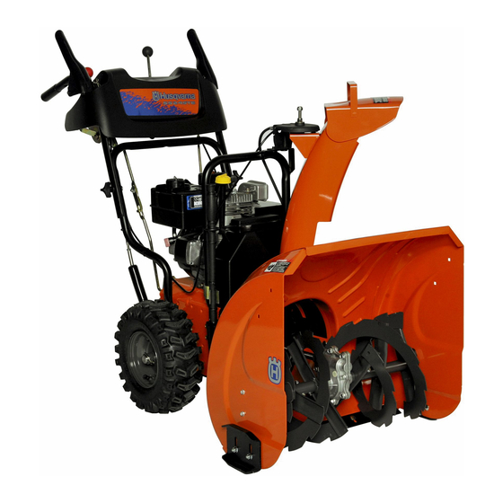
- Page 1 2008-01 Operator's Manual O0802004 Snow Thrower 5524 STE 961930014-03 Operator's Manual...
-
Page 2: Safety Rules
IMPORTANT Safe Operation Practices for Walk-Behind Snow Throwers This snow thrower is capable of amputating hands and feet and throwing objects. Failure to observe the following safety instructions could result in serious injury. WARNING: Snow throwers have ex- Look for this symbol to point out im- posed rotating parts, which can cause por tant safety precautions. -
Page 3: Table Of Contents
6. When cleaning, repairing or inspecting the snow thrower, Clearing a Clogged Discharge Chute stop the engine and make certain the collector/impel- Hand contact with the rotating impeller inside the discharge ler and all moving parts have stopped. Disconnect chute is the most common cause of injury associated with the spark plug wire and keep the wire away from the snow throwers. -
Page 4: Assembly / Pre-Operation
PARTS PACKED SEPARATELY IN CARTON ASSEMBLY / PRE-OPERATION Read these instructions and this manual in its entirety 2. Cut down all four corners of carton and lay panels flat. before you attempt to assemble or operate your new 3. Remove the two (2) screws securing the auger housing snow thrower. - Page 5 ASSEMBLY / PRE-OPERATION NOTE: The multi-wrench may be used for assembly of the INSTALL TRACTION DRIVE CONTROL ROD chute rotator head to snow thrower and making ad just ments (See Figs. 3 and 4) to the skid plates. The traction drive control rod has the long loop on the end of the spring as shown.
-
Page 6: Assembly / Pre-Operation
ASSEMBLY / PRE-OPERATION INSTALL AUGER CONTROL ROD (See Figs. 5 and 6) INSTALL DISCHARGE CHUTE / CHUTE ROTATER HEAD (See Fig. 7) The auger control rod has the short loop on the end of the spring as shown. NOTE: The multi-wrench provided in your parts bag may be used to install the chute rotater head. -
Page 7: Operation
OPERATION KNOW YOUR SNOW THROWER READ THIS OWNER'S MANUAL AND ALL SAFETY RULES BEFORE OPERATING YOUR SNOW THROWER. Compare the illustrations with your snow thrower to familiarize yourself with the location of various controls and adjustments. Save this manual for future reference. These symbols may appear on your snow thrower or in literature supplied with the product. - Page 8 OPERATION SPARK ENGINE OIL CAP AUGER DISCHARGE CHUTE CONTROL LEVER PLUG WITH DIPSTICK CONTROL SAFETY LEVER DRIVE SPEED IGNITION CON TROL LEVER GAS O LINE FILLER TRACTION CHUTE CHOKE DRIVE DE FLEC TOR CON- CONTROL TROL LEVER FUEL SHUT-OFF VALVE THROTTLE / ENGINE CONTROL...
- Page 9 OPERATION The operation of any snow thrower can result TO USE CHOKE CON TROL (See Fig. 11) in foreign objects thrown into the eyes, which The choke con trol is located on the en gine. Use the choke can result in severe eye damage. Always wear control when ev er you are starting a cold en gine.
- Page 10 OPERATION • Restart the engine, then squeeze the auger control lever to the handle to clear snow from the auger hous- HIGH ing and the discharge chute. POSITION DISCHARGE CHUTE KNOB CLEAN-OUT TOOL MOUNTING CLIP CHUTE DEFLECTOR LOW POSITION FIG. 13 TO THROW SNOW (See Fig.
-
Page 11: Before Starting The Engine
OPERATION TO ADJUST SKID PLATES (See Fig. 17) WARNING: Wipe off any spilled oil or NOTE: The wrench provided in your parts bag may be fuel. Do not store, spill or use gasoline used to adjust the skid plates. near an open flame. Skid plates are located on each side of the auger housing and adjust the clearance between the scraper bar and the CAUTION: Alcohol blended fuels (called gas-... -
Page 12: Snow Throwing Tips
OPERATION COLD START - ELECTRIC STARTER IF RECOIL STARTER HAS FROZEN If the recoil starter has frozen and will not turn the engine, 1. Insert safety ignition key (packed separately in parts bag) into ignition slot until it clicks. DO NOT turn the key. proceed as follows: Keep the extra safety ignition key in a safe place. -
Page 13: Maintenance Schedule
MAINTENANCE GENERAL REC OM MEN DA TIONS LUBRICATION CHART The warranty on this snow thrower does not cover items ➀ that have been sub ject ed to operator abuse or negligence. SAE 30 Motor Oil To receive full value from the warranty, operator must ➁... - Page 14 MAINTENANCE V-BELTS TO CHANGE ENGINE OIL Check V-belts for deterioration and wear after every 50 Determine temperature range anticipated before next oil hours of operation and replace if necessary. The belts change. All oil must meet API service classification SG–SL. are not ad just able.
-
Page 15: Service And Adjustments
SERVICE AND ADJUSTMENTS 1. Disengage all controls and move throttle control to STOP position. Wait for all moving parts to stop. WARNING: To avoid serious injury, before performing any service or ad- 2. Remove safety ignition key and disconnect spark plug just ments: wire from spark plug. -
Page 16: To Replace Belts
SERVICE AND ADJUSTMENTS TO REPLACE BELTS (See Fig. 21) The auger and traction drive belts are not adjustable. If the HINT: Insert a 3/8" drive ratchet (in the “ON” position) into belts are damaged or begin to slip from wear, they should the square hole in idler arm and rotate ratchet clockwise be replaced. -
Page 17: Storage
TO REMOVE WHEELS (See Fig. 22) NOTE: To seal punctures or prevent flat tires due to slow leaks, tire sealant may be purchased from your local parts • Remove the klik pin and remove wheel from axle. dealer. Tire sealant also prevents tire dry rot and cor ro sion. IMPORTANT: When installing wheel, be sure to use the in- nermost hole in axle and the wheel hub hole. -
Page 18: Troubleshooting
TROUBLESHOOTING See appropriate section in manual unless directed to a qualified service centre. PROBLEM CAUSE CORRECTION Does not start 1. Fuel shut-off valve (if so 1. Turn fuel shut-off valve to OPEN position. equipped) in OFF position. 2. Safety ignition key 2. - Page 19 SERVICE NOTES...
-
Page 20: Repair Parts
REPAIR PARTS AUGER HOUSING / IMPELLER ASSEMBLY SNOW THROWER - MODEL NO. 5224STE 5224STE (96193001403), PRODUCT NO. 961 93 00-14... - Page 21 REPAIR PARTS AUGER HOUSING / IMPELLER ASSEMBLY SNOW THROWER - MODEL NO. 5224STE 5224STE (96193001403), PRODUCT NO. 961 93 00-14 KEY PART KEY PART DESCRIPTION DESCRIPTION 532 19 10-79 Pulley, Impeller 532 40 78-66 Auger Assembly, LH 532 18 89-09 Bearing Assembly, Flange 532 40 77-68 O-Ring...
- Page 22 REPAIR PARTS CONTROL PANEL / DISCHARGE CHUTE SNOW THROWER - MODEL NO. 5224STE 5224STE (96193001403), PRODUCT NO. 961 93 00-14 07_Chute-knob_2...
- Page 23 REPAIR PARTS CONTROL PANEL / DISCHARGE CHUTE SNOW THROWER - MODEL NO. 5224STE 5224STE (96193001403), PRODUCT NO. 961 93 00-14 KEY PART DESCRIPTION 532 41 42-81 Knob, Lever 817 50 10-10 Screw #10-24 x 5/8 532 18 41-14 Strap, Slotted 873 80 06-00 Nut, Lock 3/8-16 819 13 13-16...
- Page 24 REPAIR PARTS HANDLES SNOW THROWER - MODEL NO. 5224STE 5224STE (96193001403), PRODUCT NO. 961 93 00-14...
- Page 25 REPAIR PARTS HANDLES SNOW THROWER - MODEL NO. 5224STE 5224STE (96193001403), PRODUCT NO. 961 93 00-14 KEY PART DESCRIPTION 532 41 55-42 Lever, Auger Control, RH 532 41 55-41 Lever, Traction Drive Control, LH 532 16 96-75 Retainer, Hairpin 817 06 04-08 Screw, Hex Head 532 41 26-77 Rod, Interlock...
- Page 26 REPAIR PARTS DRIVE SNOW THROWER - MODEL NO. 5224STE 5224STE (96193001403), PRODUCT NO. 961 93 00-14 9 10 Drive 2006...
- Page 27 REPAIR PARTS DRIVE SNOW THROWER - MODEL NO. 5224STE 5224STE (96193001403), PRODUCT NO. 961 93 00-14 KEY PART DESCRIPTION 532 75 11-53 Nut, Lock 5/16-18 817 49 05-08 Screw, Hex Head 5/16-18 x 1/2 532 18 00-17 Bearing, Flange 532 18 01-34 Shaft, Auxiliary 532 17 92-70 Spacer, Plate...
- Page 28 REPAIR PARTS CHASSIS / ENGINE / PULLEYS SNOW THROWER - MODEL NO. 5224STE 5224STE (96193001403), PRODUCT NO. 961 93 00-14 10 21 6 40...
- Page 29 REPAIR PARTS CHASSIS / ENGINE / PULLEYS SNOW THROWER - MODEL NO. 5224STE 5224STE (96193001403), PRODUCT NO. 961 93 00-14 KEY PART KEY PART DESCRIPTION DESCRIPTION 532 18 10-44 Spring, Traction Idler 532 15 54-52 Guide, Belt 532 18 05-22 Pulley, Idler (2-1/4) 532 19 22-13 Belt Cover Assembly...
- Page 30 REPAIR PARTS WHEELS / DECALS SNOW THROWER - MODEL NO. 5224STE 5224STE (96193001403), PRODUCT NO. 961 93 00-14 Wheels-no PS 1 10...
-
Page 31: Repair Parts
532 19 21-56 Decal, Husqvarna 532 18 10-35 Decal, Danger, Deflector 532 18 10-42 Decal, Danger 532 19 21-55 Decal, Husqvarna, 5524STE 532 18 10-33 Decal, Instruction 532 41 53-91 Decal, Traction Lever 532 41 53-90 Decal, Auger Lever 532 41 54-75...