Table of Contents
Advertisement
Quick Links
Download this manual
See also:
User Manual
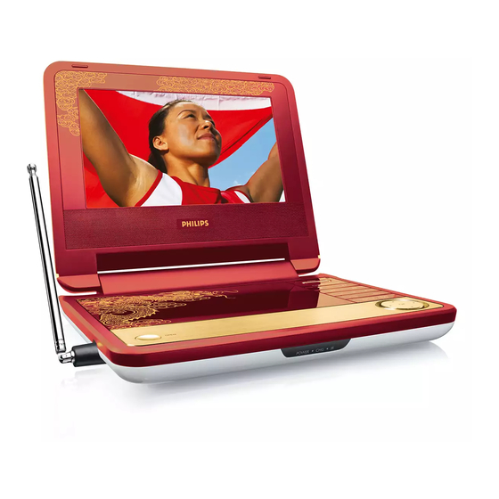
DVD Portable Player
Service Manual
TABLE OF CONTENTS
Technical Specification & Service Tips......................... 1
Safety Instructions..................................................... 2
Instruction for Use...................................................... 3
Mechanical Instructions.............................................. 4
Troubleshooting .........................................................5
Overall Block Diagram................................................. 6
Overall Wiring Diagram................................................7
Electrical Diagram...................................................... 8
Component Layout.................................................... 9
Service Part List......................................................... 10
Revision List............................................................. 11
©Copyright 2005 Philips Consumer Electronics B.V. Eindhoven, The Netherlands
All rights reserved. No part of this publication may by reproduced, stored in a
retrieval system or transmitted, in any form or by any means, electronics,
mechanical, photocopying, or otherwise without the prior permission of Philips
Version 1.0
PET2008/93
Chapter
3141 785 32630
Advertisement
Table of Contents

Related Manuals for Philips PET2008/93


Summary of Contents for Philips PET2008/93
-
Page 1: Table Of Contents
All rights reserved. No part of this publication may by reproduced, stored in a retrieval system or transmitted, in any form or by any means, electronics, mechanical, photocopying, or otherwise without the prior permission of Philips 3141 785 32630 Version 1.0... -
Page 2: Technical Specification
1.0 TECHNICAL SPECIFICATION Playback disc type: DVD, Picture-CD, General SVCD, Video CD, MP3- CD, CD-R/CD-RW, WMA-CD, DVD-R, DVD- Dimensions (W x H x D): 293 x 170 x 33 mm RW, DVD+R, DVD+RW Weight: 0.85kg Power supply: DC 9V 1.8A Power consumption: Video Playback Format: DVD / VCD / JPEG... - Page 3 For the best performance of your DVD Portable. Check www.philips.com/support for latest software upgrades available. Download the latest software from the Philips support site Region code “0” can be used for all regions! Unzip the files and then burn it into a CD-ROM to...
- Page 4 2.0 SAFTETY INSTRUCTIONS WAARSCHUWING WARNING Alle IC’s en vele andere halfgeleiders zijn All ICs and many other semi-conductors are gevoelig voor electrostatische ontladingen susceptible to electrostatic discharges (ESD). (ESD). Careless handling during repair can reduce life Onzorgvuldig behandelen tijdens reparatie kan drastically.
- Page 5 2.1 ESD PROTECTION When the power supply is being turned on, you may not remove this laser cautions label. If it removes, radiation of laser may be received. PREPARATION OF SERVICING Pickup Head consists of a laser diode that is very susceptible to external static electrocity. Although it operates properly after replacement, if it was subject to electrostatic discharge during replacement, its life might be shortened.
- Page 6 SAFTY NOTICE SAFTY PRECAUTIONS LEAKAGE CURRENT CHECK Plug the AC line cord directly into a 120V AC outlet (do Measure the AC voltage across the 1500 resistor. not use an isolation transformer for this check). Use an The test must be conducted with the AC switch on and AC voltmeter, having 5000 per volt or more sensitivity.
-
Page 7: Instruction For Use
3.0 INSTRUCTIONS FOR USE DVD PLAYER LAYOUT OPEN POWER/IR/CHR Opens disc door to insert or Power /remote sensor /charging remove disc indicator. Confirms selection PHONES 1 & 2 POWER Headphones jack Switches the player on / off A/V OUT Audio/video output jack A/V IN Press once to stop playback Audio/video input jack... -
Page 8: Remote Control
REMOTE CONTROL MENU SUBTITLE Display MENU page. Subtitle language selector. , , , RETURN Up / down / left / right For VCD menu page. navigation key. A - B To repeat or loop a sequence Confirm seletion. in a title. VOL +/- SETUP Volume control. - Page 9 4.0 MECHNICAL INSTRUCTIONS 1. Back side of the set as shown in Fig.1 5. Remove speaker grill and screw cushion on display frame Remove the screws on the base cover. as shown in Fig.5 Fig.1 Fig.5 2. Soldered short pattern for laser diode as shown in Fig.2 6.
-
Page 10: Troubleshooting
5.0 TROUBLESHOOTING SYMPTOM: NO POWER, NO GREEN LED start Check if the power cable replace cable/ No defect, return set OK? adapter set to customer AC adapter Check if the replace connector power and play and switch unit button OK? replace MAIN go to other BOARD... - Page 11 5.0 TROUBLESHOOTING SYMPTOM: THE INITIAL SCREEN IS NOT DISPLAYED ON THE LCD Refer to the symptom NO start POWER, NO GREEN LED Replace broken Check if the Repair connector harness LED on the front lights up? Remove the LCD Open the top and Is the cover and plate of Check if the...
- Page 12 5.0 TROUBLESHOOTING SYMPTOM: THE DVD DRIVE DOES NOT WORK Press the DISC cover switch at the center of the DVD player and turn on the power. Then check whether or not the optical pick- up lens of the DVD drive lights. CAUTION: start Visible laser radiation when open and interlock defeated.
- Page 13 5.0 TROUBLESHOOTING SYMPTOM: THE DVD DRIVE DOES NOT OPERATE WITH BATTERY start Install a good battery does the LED lights up orange while the AC adapter is connected and does the DVD drive operate OK? NOTE: - For this check, use a battery which is not fully Replace battery charged (because the LED does not light when the battery is fully charged.)
-
Page 14: Overall Block Diagram
6.0 OVERALL BLOCK DIAGRAM (PET738) OSCILLATOR DC 9V 16M FlashROM 64M SDRAM OZ9RR TC4W53 74HCU04 27MHz KH29LV160CBTC-70G HY57V641620ETP-7-C 27MHz MX88V462UCG HIGH VOLTAGE ASS'Y TFT MONITOR RF AMP & SERVO & DVD PROCESSOR DV23FC MPEG-2 DECODER & VIDEO ENCODER PU mechanism MT1389DE/H-L VIDEO IN +3.3V... -
Page 15: Overall Wiring Diagram
7.0 OVERALL WIRING DIAGRAM (for PET735/PET738) BATTERY POWER PCB COM# TFT5V -13V TFT5V SPIO TFT3.3V CPH1 CD/DVDSW TFT3.3V CPH1 CPH1 MOD1 SPL+ SPL- L/R# LD/VCC SPR- SPR+ LD/CD LD/DVD TFTON RESET462 MAIN PCB TFT5V SCL# TFT5V #SDA VRDVD VIDEO IN +16V VD/CD -13V... - Page 16 8.0 ELECTRICAL DIAGRAM (PET738) MAIN BOARD CIRCUIT DIAGRAM (MT1389HD) JITFO JITFN 100pF 100pF DV33 TP96 TP96 TP172 TP172 0.1uF 0.1uF CB66 CB66 CB75 CB75 750k 750k ADACVDD C113 C113 C177 C177 2200pF 2200pF C179 C179 100nF 100nF APLLVDD3 0.1uF 0.1uF 10uF/10v 10uF/10v DACVDDB...
- Page 17 8.0 ELECTRICAL DIAGRAM (PET738) MAIN BOARD CIRCUIT DIAGRAM (AUDIO) 12V-OP C523 100N C523 100N R527 R527 VD510 VD510 A-L# R530 R530 C509 C509 47U/4V 47U/4V 10U/10V 10U/10V 2SD601 2SD601 HSJ1594-010060 HSJ1594-010060 JS1.3 R515 R515 C518 300P C518 300P N501 N501 C508 C508 47U/4V...
- Page 18 8.0 ELECTRICAL DIAGRAM (PET738) MAIN BOARD CIRCUIT DIAGRAM (FLASH AND SDRAM) MA[0..11] MA[0..11] AD[0..7] D001 D001 AD[0..7] DQ[0..15] D004 D004 DQ[0..15] DV33 10U/10V 10U/10V MA10 DQ10 A10/AP DQ10 MA11 DQ11 CB113 CB113 DQ11 DQ12 BA0/A13 DQ12 DQ13 BA1/A12 DQ13 A[0..21] DQ14 A[0..21] 1 DQ14...
- Page 19 8.0 ELECTRICAL DIAGRAM (PET738) MAIN BOARD CIRCUIT DIAGRAM (MCU AND TUNER) KEYAD1 KEYAD0 POWER-KEY MLV0805HAO018 MLV0805HAO018 R137 R137 R136 R136 R135 R135 CPU3.3V CPU3V3 10u/10v 10u/10v R149 R149 CPU3.3V DOWN3 DOWN3 DOWN1 DOWN1 N002 N002 MC9S08AW60-64 MC9S08AW60-64 HXT5G02A HXT5G02A TUNER1 TUNER1 ANT_IN PTC4...
- Page 20 8.0 ELECTRICAL DIAGRAM (PET738) MAIN BOARD CIRCUIT DIAGRAM (POWER AND CHARGE) BATT+ BATT+ INTBATT-AD 10uF/16V 10uF/16V 7x1 W/HOUSING 7x1 W/HOUSING 7x1 W/HOUSING 7x1 W/HOUSING DIP7/W/H/P2.54 DIP7/W/H/P2.54 DIP7/W/H/P2.54 DIP7/W/H/P2.54 D413 D413 Q401A Q401A Q402A Q402A AO4801 AO4801 AO4801 AO4801 B240A B240A CATION:REPLACE PUSE WITH SAME D402 D402...
-
Page 21: Electrical Diagram
8.0 ELECTRICAL DIAGRAM (PET738) CONNECT BOARD CIRCUIT DIAGRAM (MX88V462) Crystal R0206 R0206 100K 100K CLK_IN CLK_OUT COM# COM# COM# R0143 R0143 TFT-13V TFT-13V C144 C144 27MHz 27MHz SPIO 20pF 20pF TVVIDEO C146 C146 B240A B240A 20pF 20pF MOD1 VIDEOIN 10uF/16V 10uF/16V 10uF/16V 10uF/16V... -
Page 22: Component Layout
9.0 COMPONENT LAYOUT PET738M MAIN BOARD DIAGRAM (TOP) PET738M MAIN BOARD DIAGRAM (BOTTOM) - Page 23 9.0 COMPONENT LAYOUT PET735K KEY BOARD DIAGRAM PET738T IF BOARD DIAGRAM...
-
Page 24: Service Part List
10.0 SERVICE PART LIST Electrical Part List: Service Service Description Photo Pos. 12NC PET738M MAIN PCB 996510006298 ASS’Y/93 996510006299 PET738T IF PCB ASS’Y PET735K FUNCTION 996510003006 PCB ASS’Y PET730X BATTERY 996510001273 ASS’Y 24 PIN HARDNESS-180- 996510001274... - Page 25 Service Description Photo Pos. 12NC LB070W02-TME1-SC TFT 996510001275 996510004977 DV23FC LOADING ASS’Y 994000002157 YD2027 SPEAKER SPEAKER GRILL 996510015787 PET2008/93 (RED COLOR) 996510006300 TOP COVER PET73X DISPLAY FRAME 996510015783 PET2008/93 (RED COLOR) MIDDLE CAB & BUTTON 996510015785 ASSY PET2008/93 (RED COLOR)
- Page 26 10.0 SERVICE PART LIST Mechanical Part List: Service Service Description Photo Pos. 12NC 996510003008 BASE COVER 996510001282 ADJUST HINGE PET73X DOOR DISCRETENESS 996510015784 PET2008/93 (RED COLOR) LENS REMOTE SENSOR 996510015786 PET2008/93 (RED COLOR) 996510015788 DOOR LOCK PET2008/93...
- Page 27 10.0 SERVICE PART LIST Accessories Part List: Service Service Photo Pos. No. 12NC Description ADPV25A AC 9965100039077 POWER ACAPT ADAPTOR/93 996510001124 CIGARETTE CARAPT ADAPTER 994000001912 AV CABLE AVCABLE AY5511 996510004319 REMOTE CONTROL CAR MOUNT 996510001130 MOUNT AY4246 996510004318 ANTENNA...
-
Page 28: Revision List
11.0 REVISION LIST Version 1.0 (3141 785 32630) • Initial release PET2008/93...