Hitachi DH 40MRY Technical Data And Service Manual
Hide thumbs
Also See for DH 40MRY:
- Handling instructions manual (61 pages) ,
- Technical data and service manual (14 pages) ,
- Instruction manual (48 pages)

Related Manuals for Hitachi DH 40MRY


Summary of Contents for Hitachi DH 40MRY
- Page 1 MODEL DH 40MRY Hitachi Power Tools TECHNICAL DATA ROTARY HAMMER DH 40MRY SERVICE MANUAL LIST No. E493 Oct. 2006 SPECIFICATIONS AND PARTS ARE SUBJECT TO CHANGE FOR IMPROVEMENT...
- Page 2 REMARK: Throughout this TECHNICAL DATA AND SERVICE MANUAL, symbols are used in the place of company names and model names of our competitors. The symbols utilized here are as follows: Competitors Symbols Utilized Company Name Model Name MAKITA HR4011C GBH5-40DE BOSCH...
-
Page 3: Table Of Contents
7-1. Handling Instructions ........................11 8. REFERENCE INFORMATION ...................... 12 8-1. Grease Replacement ........................12 8-2. O-ring Replacement ........................12 8-3. Structure of the Model DH 40MRY Rotary Hammer ..............12 9. REPAIR GUIDE ..........................18 9-1. Disassembly ..........................18 9-2. Reassembly ..........................20 9-3. -
Page 4: Product Name
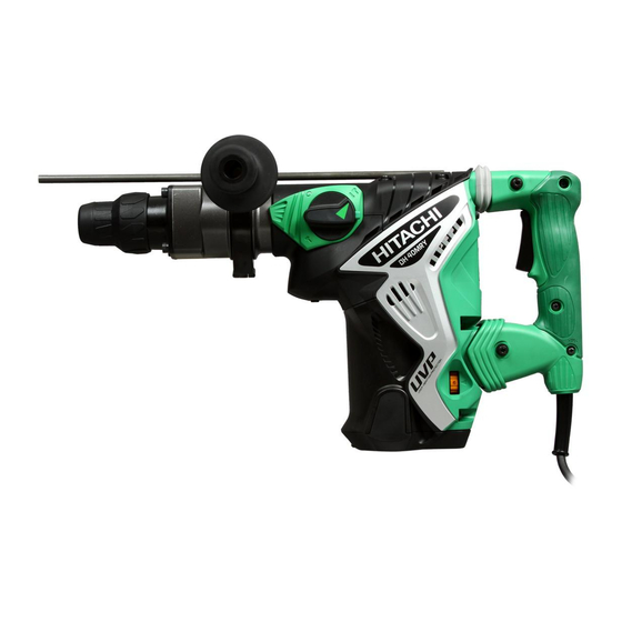
Hitachi Rotary Hammer, Model DH 40MRY 2. MARKETING OBJECTIVE The Model DH 40MRY is an upgraded version of the current Model DH 40MR that features the capability of drilling maximum 40-mm diameter holes into concrete and the use of SDS-max shank tools. The performance, durability and operability are greatly improved. -
Page 5: Selling Points
4-2-1. Lowest vibration, fastest drilling speed and highest demolishing performance in this class The vibration level of the Model DH 40MRY is lowest in the class. Therefore, the vibration exposure limit time is longest in the class. Even so, the drilling speed and the demolishing performance are 10% higher than those of similar products. - Page 6 4-2-2. Vibration reduction mechanism (Dynamic damper with leaf spring) The Model DH 40MRY is equipped with Hitachi's own dynamic damper that absorbs vibration from the main body by means of resonance of the leaf spring and the spindle. As a result, the vibration level of the Model DH 40MRY is remarkably lower than the current Model DH 40MR.
-
Page 7: Specifications
5. SPECIFICATIONS 5-1. Specifications Capacity Drill bit (Max. diameter): 40 mm (1-9/16") Core bit (Max. diameter): 105 mm (4-1/8") Power source AC single phase 50 Hz or 60 Hz Voltage 110 V 120 V 220 V 230 V 240 V Current 10 A 9.2 A... - Page 8 2. Drilling work for anchor holes (Rotation and hammering) Drill bit (Taper shank) (2) Taper shank adapter (1) Drill bit (Taper shank) (SDS-max shank) (3) Cotter (1) Drill bit (Taper shank) (2) Taper shank adapter (3) Cotter Code No. Code No. Taper dimension Code No.
- Page 9 (3) Core bit Outer Outer Outer Code No. Code No. Code No. diameter (mm) diameter (mm) diameter (mm) 25 (1") 79 (3-1/8") 955994 50 (2") 955157 959706 29 (1-1/8") 94 (3-11/16") 54 (2-1/8") 955995 956004 955155 32 (1-1/4") 100 (3-15/16") 955996 60 (2-3/8") 959710...
- Page 10 6. Demolition work (Hammering) (1) Bull point (SDS-max shank) Overall length Code No. 280 mm (11") 313471 400 mm (15-3/4") 313472 7. Grooving and edging (Hammering) (1) Cold chisel (SDS-max shank) Overall length Code No. 280 mm (11") 313473 400 mm (15-3/4") 313474 8.
- Page 11 10. Surface roughing work (Hammering) (1) Bushing tool (2) Shank (SDS-max shank) Code No. Overall length Code No. 313477 313479 220 mm (8-21/32") 11. Tamping work (Hammering) (1) Rammer (2) Shank (SDS-max shank) Code No. Overall length Code No. 313478 313479 220 mm (8-21/32") 12.
-
Page 12: Comparisons With Similar Products
6. COMPARISONS WITH SIMILAR PRODUCTS 6-1. Specification Comparisons Maker Model • HITACHI HITACHI Item DH 40MRY DH 40MR 40 (1-9/16") 40 (1-9/16") 40 (1-9/16") Drill bit dia. (mm) 40 (1-9/16") Capacity 105 (4-1/8") 105 (4-1/8") Core bit dia. (mm) 105 (4-1/8") 105 (4-1/8") -
Page 13: Drilling Speed Comparison
Drilling speed varies considerably depending on the work conditions. Use the factory test results shown in Fig. 1 for comparison purposes only. Drilling speed (mm/min) Drill bit Maker Model dia. (mm) HITACHI DH 40MRY HITACHI DH 40MR HITACHI DH 40MRY HITACHI DH 40MR DH 40MRY... -
Page 14: Chiseling Performance Comparison
7. PRECAUTIONS IN SALES PROMOTION In the interest of promoting the safest and most efficient use of the Model DH 40MRY Rotary Hammer by all of our customers, it is very important that at the time of sale the salesperson carefully ensures that the buyer seriously recognizes the importance of the contents of the Handling Instructions, and fully understands the meaning of the precautions listed on the Caution Plate attached to each tool. -
Page 15: Reference Information
8-1. Grease Replacement The striking portion and the speed reduction portion of the Model DH 40MRY respectively use different types of grease. It is not necessary to replenish the grease unless the tool is disassembled for repair or there is grease leakage due to a damaged seal. - Page 16 Dynamic damper with leaf spring The vibration caused by hammering operation of the Model DH 40MRY is transmitted to the cylinder crank case, back cover, housing and finally to the weight Vibration of through the leaf spring supporting portion. Then the...
- Page 17 Mechanism to prevent idle hammering The mechanism against idle hammering of the Model DH 40MRY is about the same as the Model DH 40MR in which, when the drill bit or the bull point is not pressed against a concrete or similar material, the second hammer moves to a position as shown in Fig.
- Page 18 Slip clutch mechanism The slip clutch mechanism is described below with reference to Fig. 8. The bevel pinion and the gear holder are coupled together by the key and press-fitting. Spring (C) and needle pins are housed in elongated grooves of the gear holder.
- Page 19 Handle and side handle The handle section is of a two-layer structure. The base is made of glassfiber-reinforced plastic and the outside layer is soft resin. They are molded in one piece. The side handle also has a two-layer structure. The base is made of glassfiber-reinforced plastic base with a steel nut and the outside layer is soft resin.
- Page 20 (for drilling) and bull points (for chiseling) have the Cylinder same shape. When chiseling or chipping with the Model DH 40MRY, it is necessary to stop the rotation and choose the "Hammering only" mode by means of the change lever to lock the working tool against rotation.
-
Page 21: Repair Guide
9. REPAIR GUIDE The numbers in [Bold] correspond to the item numbers in the Parts List and the exploded assembly diagram for the Model DH 40MRY. 9-1. Disassembly (1) Disassembly of the tool holder Pull the Grip [2] in the arrow direction fully as shown in Fig. 15. - Page 22 Retainer Sleeve [17] Lock Sleeve [29] Cylinder [26] Clutch [31] Bevel Gear [32] Piston [34] Connecting Rod [35] Second Hammer [20] Striker [24] Cylinder Crank Case [46] Crank Shaft [41] Bevel Pinion [48] Fig. 17 (3) Disassembly of the first gear and the crank shaft Remove grease from the Connecting Rod [35] side and the First Gear [61] side of the Cylinder Crank Case [46].
-
Page 23: Reassembly
(4) Disassembly of the slip clutch assembly Press the end surface Remove the Ball Bearing 629VVC2PS2L [59] with a of the bevel pinion with a hand press. bearing puller. Place the assembly on a sleeve-type support facing Washer (A) [53] downward as shown in Bevel Pinion [48] Fig. - Page 24 (2) Mounting the piston Insert the Piston Pin [33] into the 8-mm dia. hole (marked side) of the Piston [34] and the Connecting Rod [35] then press-fit it. Mount the O-ring [25] to the Piston [34]. Be careful not to protrude the Piston Pin [33] from the outside diameter of the Piston [34].
- Page 25 Needle Pin D6 x 6 [18] Damper Washer [21] Lock Sleeve [29] Lock Spring [27] Striker [24] Clutch [31] Second Hammer [20] Bevel Gear [32] Retainer Sleeve [17] Cylinder [26] Cylinder Crank Case [46] Retaining Ring D35 [13] Clutch Spring [30] Ball Bearing 6007DDUAV2S [14] Damper...
- Page 26 Gear [57]. Insert the ten Needles [56] being careful not to incline them, then push in ten Springs (C) [55] as shown in Fig. 25. Fill the slots and the through holes of the Gear Holder [54] with Hitachi Motor Grease No.
- Page 27 (6) Mounting the handle shaft and handle (A) Holder [111] Push the Holder [111] in the Back Cover [96] by hand. Convex mark At this time, check that the clearance of the Holder [111] does not protrude from the main body and the Holder [111] does not protrude from the end surface of the Back Cover [96].
- Page 28 Mount the Spring Base [134] to the Housing Cylinder Crank Case [46] Ass'y [123] being careful of the mounting direction. Mount one Needle Roller [70] to the Cylinder Crank Case [46] and three Needle Rollers [70] to the Spring Base [134]. Before mounting, apply grease to the Needle Rollers [70] to avoid being removed (Fig.
-
Page 29: Screw Locking Agent Tb1401
Cylinder Crank Case [46] on the clutch side. Apply Hitachi Motor Grease No. 29 to the Needle Bearing (M661) [62], pinion portion of the Armature Ass'y [78] and Needle Roller D8 x 20 [16]. Fill 30 g of the Hitachi Motor Grease No. -
Page 30: Internal Wiring
+ 1.96 + 20 Crank cover mounting bolt ............7.84 m (80 • • (Hex. socket head bolt M5 x 16) Weight mounting bolt (Hex. socket head bolt M5 x 12) + 1.96 + 20 Handle mounting bolt ..............4.9 m (50 •... -
Page 31: Insulation Tests
Mounting diagram for products with noise suppressor Lead wires of switch and cord Case (A) Housing Control circuit ass'y (including noise suppressor) Lead wire of stator Lead wire of noise suppressor Tail cover Fig. 31 9-6. Insulation Tests On completion of disassembly and repair, measure the insulation resistance and dielectric strength. Insulation resistance: 7 M Ω... -
Page 32: Standard Repair Time (Unit) Schedules
10. STANDARD REPAIR TIME (UNIT) SCHEDULES Variable 60 min. MODEL Fixed DH 40MRY Work Flow Housing Ass'y Stator Ass'y Handle (A).(B) Gear Cover Needle Bearing Switch (B) Cord Armature Ass'y Transatory Unit Ball Bearing Handle Damper (6201DD) Handle Damper Ball Bearing... - Page 33 Hitachi Power Tools LIST NO. E493 ELECTRIC TOOL PARTS LIST ROTARY HAMMER 2006 • • Model DH 40MRY (E1)
- Page 34 PARTS DH 40MRY ITEM CODE NO. DESCRIPTION REMARKS USED 321-306 FRONT CAP 321-305 GRIP 318-590 STOPPER RING 321-304 NEEDLE HOLDER 321-303 RETAINER SPRING 321-302 SPRING HOLDER (A) 981-942 SEAL LOCK HEX. SOCKET HD. BOLT M6X25 321-300 FRONT COVER 956-996 O-RING (1AS-60)
- Page 35 PARTS DH 40MRY ITEM CODE NO. REMARKS DESCRIPTION USED 313-058 WASHER 313-053 WASHER (A) 321-281 GEAR HOLDER 321-282 SPRING (C) 320-343 NEEDLE 321-280 SECOND GEAR 321-283 SPACER 629-VVM BALL BEARING 629VVC2PS2L 944-525 BEARING WASHER (C) 321-276 FIRST GEAR 939-299 NEEDLE BEARING (M661)
- Page 36 PARTS DH 40MRY ITEM CODE NO. DESCRIPTION REMARKS USED 310-123 TRANSATORY UNIT 326-485 HANDLE (A).(B) SET 991-711 DISTANCE PIECE (B) 991-690 SEAL LOCK HEX. SOCKET HD. BOLT M5X12 326-472 HOOD 307-028 TAPPING SCREW (W/FLANGE) D4X25 (BLACK) 310-124 HANDLE DAMPER 326-377...
-
Page 37: Standard Accessories
STANDARD ACCESSORIES DH 40MRY ITEM CODE NO. DESCRIPTION REMARKS USED 981-840 GREASE (A) FOR HAMMER.HAMMER DRILL (30G) 326-489 CASE (PLASTIC) OPTIONAL ACCESSORIES ITEM CODE NO. DESCRIPTION REMARKS USED 308-471 GREASE FOR HAMMER. HAMMER DRILL (70G) 980-927 GREASE FOR HAMMER. HAMMER DRILL (500G) - Page 38 OPTIONAL ACCESSORIES DH 40MRY ITEM CODE NO. DESCRIPTION REMARKS USED 956-002 CORE BIT 64MM 1 INCLUD. 643 956-003 GUIDE PLATE (FOR CORE BIT 64MM) 955-157 CORE BIT 79MM 1 INCLUD. 645 955-168 GUIDE PLATE (FOR CORE BIT 79MM) 956-004 CORE BIT 94MM 1 INCLUD.