Table of Contents
Advertisement
Service
Manual
HIGH POWER CD PLAYER WITH RDS TUNER
DEH-3130R
DEH-3100R-B
DEH-3100R
- This service manual should be used together with the following manual(s):
Model No.
Order No.
CX-958
CRT2423
CONTENTS
1. SAFETY INFORMATION ............................................2
2. EXPLODED VIEWS AND PARTS LIST .......................3
4. PCB CONNECTION DIAGRAM ................................28
5. ELECTRICAL PARTS LIST ........................................38
6. ADJUSTMENT..........................................................44
PIONEER CORPORATION
PIONEER ELECTRONICS SERVICE INC.
PIONEER ELECTRONIC [EUROPE] N.V.
PIONEER ELECTRONICS ASIACENTRE PTE.LTD. 253 Alexandra Road, #04-01, Singapore 159936
C PIONEER CORPORATION 1999
DEH-3130R/X1N/EW
Mech. Module Remarks
S8.1
CD Mech. Module:Circuit Description, Mech.Description, Disassembly
4-1, Meguro 1-Chome, Meguro-ku, Tokyo 153-8654, Japan
P.O.Box 1760, Long Beach, CA 90801-1760 U.S.A.
Haven 1087 Keetberglaan 1, 9120 Melsele, Belgium
1
X
N/EW
1
X
N/EW
7. GENERAL INFORMATION .......................................48
7.1 DIAGNOSIS ........................................................48
7.1.1 TEST MODE ..............................................48
7.1.2 DISASSEMBLY .........................................52
7.2 PARTS .................................................................56
7.2.1 IC................................................................56
7.2.2 DISPLAY ....................................................63
8. OPERATIONS AND SPECIFICATIONS.....................64
ORDER NO.
CRT2418
1
X
N/EW
K-ZZD. OCT. 1999 Printed in Japan
Advertisement
Table of Contents

Related Manuals for Pioneer DEH-3130R


Summary of Contents for Pioneer DEH-3130R
-
Page 1: Table Of Contents
PIONEER ELECTRONICS SERVICE INC. P.O.Box 1760, Long Beach, CA 90801-1760 U.S.A. PIONEER ELECTRONIC [EUROPE] N.V. Haven 1087 Keetberglaan 1, 9120 Melsele, Belgium PIONEER ELECTRONICS ASIACENTRE PTE.LTD. 253 Alexandra Road, #04-01, Singapore 159936 C PIONEER CORPORATION 1999 K-ZZD. OCT. 1999 Printed in Japan... -
Page 2: Safety Information
DEH-3130R,3100R-B,3100R - CD Player Service Precautions 2. During disassembly, be sure to turn the power off 1. For pickup unit(CXX1285) handling, please refer since an internal IC might be destroyed when a con- to"Disassembly"(see page 52). nector is plugged or unplugged. -
Page 3: Exploded Views And Parts List
DEH-3130R,3100R-B,3100R 2. EXPLODED VIEWS AND PARTS LIST 2.1 PACKING NOTE: - Parts marked by “*” are generally unavailable because they are not in our Master Spare Parts List. ∇ mark on the product are used for disassembly. - Screws adjacent to (1) PACKING SECTION PARTS LIST Mark No. - Page 4 DEH-3130R,3100R-B,3100R (2) CONTRAST TABLE DEH-3130R/X1N/EW, DEH-3100R-B/X1N/EW and DEH-3100R/X1N/EW are constructed the same except for the following: Part No. Mark No. Symbol and Description DEH-3130R/X1N/EW DEH-3100R-B/X1N/EW DEH-3100R/X1N/EW 10 Carton CHG3882 CHG3883 CHG3881 11 Contain Box CHL3882 CHL3883 CHL3881 - Owner's Manual, Installation Manual Model Part No.
- Page 5 DEH-3130R,3100R-B,3100R 2.2 EXTERIOR...
- Page 6 DEH-3130R,3100R-B,3100R (1) EXTERIOR SECTION PARTS LIST Mark No. Description Part No. Mark No. Description Part No. 1 Screw BMZ26P120FMC 46 Spring CBH2367 2 Screw BSZ26P060FMC 47 Spring CBH2208 3 Screw BSZ30P060FMC 48 Bracket CNC6791 4 Screw BSZ30P120FMC 49 Holder CNC8042 5 •••••...
- Page 7 DEH-3130R,3100R-B,3100R (2) CONTRAST TABLE DEH-3130R/X1N/EW, DEH-3100R-B/X1N/EW and DEH-3100R/X1N/EW are constructed the same except for the following: Part No. Mark No. Symbol and Description DEH-3130R/X1N/EW DEH-3100R-B/X1N/EW DEH-3100R/X1N/EW 42 Chassis Unit CXB4711 CXB4709 CXB4710 51 Panel CNS5340 CNS5188 CNS5188 61 Detach Grille Assy...
- Page 8 DEH-3130R,3100R-B,3100R 2.3 CD MECHANISM MODULE...
- Page 9 DEH-3130R,3100R-B,3100R - CD MECHANISM MODULE SECTION PARTS LIST Mark No. Description Part No. Mark No. Description Part No. 1 Control Unit CWX2411 46 ••••• 2 Connector(CN802) CKS2192 47 Ball CNR1189 3 Connector(CN801) CKS2193 48 Belt CNT1086 4 Connector(CN701) CKS2773 49 Roller...
-
Page 10: Block Diagram And Schematic Diagram
DEH-3130R,3100R-B,3100R 3. BLOCK DIAGRAM AND SCHEMATIC DIAGRAM 3.1 BLOCK DIAGRAM TUNER AMP UNIT Q525 Q540 Q524 Q542 FM/AM TUNER UNIT FM FRONT END FM/AM 1ST IF 10.7MHz TMUTE FM MPX T51 Q51 CF51 CF52 CF53 ANTENNA CN502 Q701 IC 2 PM4008A... - Page 11 DEH-3130R,3100R-B,3100R tmute ldet CN431 REAR L CH Q431 FM/AM SYSTEM CONTROLLER IC 601(1/2) PE5139A SDBW TUNPCE TUNPCK TUNPCE2 TUNPDO PDIO TUNPDI Q434 LOCL Q973 BACKUP FUSE BACK UP POWER AMP IN1_L FL– ELECTRONIC VOLUME/ FL– SOURCE SELECTOR IC 551 IN2_L PAL005A RL–...
- Page 12 DEH-3130R,3100R-B,3100R 3.2 OVERALL CONNECTION DIAGRAM(GUIDE PAGE) Note: When ordering service parts, be sure to refer to “EXPLODED VIEWS AND PARTS LIST” or “ELECTRICAL PARTS LIST”. Large size TUNER AMP UNIT SCH diagram Guide page Detailed page FM : -16.5dBs AM : -27dBs FM(100%) : -15.5dBs...
- Page 13 DEH-3130R,3100R-B,3100R MUTE REAR PREOUT FM : 5.84dBs AM : -2.66dBs S-CD : 9.74dBs RESET FM : 6.6dBs AM : -1.9dBs POWER AMP S-CD : 10.5dBs FM : 32dBs AM : 24dBs S-CD : 36dBs >CEK1136 VDD REGULATOR ERA15-02VH 1K(1/2W) BACK UP SENSE...
- Page 14 DEH-3130R,3100R-B,3100R...
- Page 15 DEH-3130R,3100R-B,3100R...
- Page 16 DEH-3130R,3100R-B,3100R...
- Page 17 DEH-3130R,3100R-B,3100R...
- Page 18 DEH-3130R,3100R-B,3100R 3.3 FM/AM TUNER UNIT FM/AM TUNER UNIT Mark Band Input Level None – – 0dBf 65dBf F125 125dBf 0dBµ 74dBµ A125 125dBµ...
- Page 19 DEH-3130R,3100R-B,3100R...
- Page 20 DEH-3130R,3100R-B,3100R 3.4 KEYBOARD UNIT KEYBOARD UNIT...
- Page 21 DEH-3130R,3100R-B,3100R : DEH-3130R/X1N/EW, 3100R/X1N/EW : DEH-3100R-B/X1N/EW DEH-3130R/X1N/EW DEH-3100R-B/X1N/EW DEH-3100R/X1N/EW D1809,1810 CL220D CL220SRCTS CL220PGC D1811 CL170DCD CL170SRCD CL170PGCD D1812,1813 CL170DCD CL170SRCD CL170PGCD S1801-1806,1808-1812,1816-1818 CSG1114 CSG1135 CSG1112 S1807,1813,1814,1819 CSG1117 CSG1133 CSG1107 R1806,1808...
- Page 22 DEH-3130R,3100R-B,3100R 3.5 CD MECHANISM MODULE CONTROL UNIT PICKUP UNIT (SERVICE)(P8) CN101 RF-AMP, SE PHOTO UNIT(S8) CN802 Q1 CPT230SX-TU Q2 CPT230SX-TU SPINDLE MOTOR M3 CXB2562 CARRIAGE MOTOR M1 CXB2190 LOADING MOTOR CD DRIVER M2 CXB2195 CN801 BA05SFP 5V REGULATOR...
- Page 23 DEH-3130R,3100R-B,3100R SWITCHES: CONTROL UNIT S801 : HOME SWITCH..ON-OFF S802 : CLAMP SWITCH..ON-OFF The underlined indicates the switch position. MP, SERVO, DSP, DAC, LPF CN701...
- Page 24 DEH-3130R,3100R-B,3100R Note:1. The encircled numbers denote measuring pointes in the circuit diagram. 2. Reference voltage REFO:2.5V - Waveforms 1 RFI 1 CH1: RFI 1 CH1: RFI 0.5V/div. 0.5µs/div. 1V/div. 1V/div. 0.5ms/div. 0.5ms/div. 2 CH2: MIRR 2 CH2: MIRR Normal mode: play 5V/div.
- Page 25 DEH-3130R,3100R-B,3100R 8 CH1: TE 8 CH1: TE 0 MD 0.2V/div. 0.5V/div. 0.5V/div. 0.1s/div. 20ms/div. 5ms/div. 9 CH2: TD ! CH2: SD 0.2V/div. 0.5V/div. Normal mode: play TEST mode: 100 Tracks jump(FWD) Normal mode: Play (12cm) → REFO → REFO →...
- Page 26 DEH-3130R,3100R-B,3100R ( CH1: R OUT 6 CH1: FE 8 CH1: TE 1V/div. 0.2V/div. 0.2V/div. 0.2ms/div. 1ms/div. 1ms/div. ) CH2: L OUT 9 CH2: TD 3 CH2: FD 1V/div. 0.5V/div. 0.5V/div. Normal mode: Play (1kHz 0dB) Normal mode: During AGC Normal mode: During AGC →...
- Page 27 DEH-3130R,3100R-B,3100R...
-
Page 28: Pcb Connection Diagram
DEH-3130R,3100R-B,3100R 4. PCB CONNECTION DIAGRAM 4.1 TUNER AMP UNIT NOTE FOR PCB DIAGRAMS TUNER AMP UNIT 1. The parts mounted on this PCB include all necessary parts for several destination. For further information for respective destinations, be sure to check with the schematic dia- gram. - Page 29 DEH-3130R,3100R-B,3100R SIDE A IP BUS IN SUB WOOFER/ REAR PREOUT L ch R ch...
- Page 30 DEH-3130R,3100R-B,3100R TUNER AMP UNIT...
- Page 31 DEH-3130R,3100R-B,3100R SIDE B...
- Page 32 DEH-3130R,3100R-B,3100R 4.2 FM/AM TUNER UNIT SIDE A...
- Page 33 DEH-3130R,3100R-B,3100R SIDE B...
- Page 34 DEH-3130R,3100R-B,3100R 4.3 KEYBOARD UNIT SIDE A ←...
- Page 35 DEH-3130R,3100R-B,3100R SIDE B...
- Page 36 DEH-3130R,3100R-B,3100R 4.5 CD MECHANISM MODULE SIDE A...
- Page 37 DEH-3130R,3100R-B,3100R SIDE B...
-
Page 38: Electrical Parts List
DEH-3130R,3100R-B,3100R 5. ELECTRICAL PARTS LIST NOTES: - Parts whose parts numbers are omitted are subject to being not supplied. - The part numbers shown below indicate chip components. Chip Resistor RS1/_S___J,RS1/__S___J Chip Capacitor (except for CQS..) CKS.., CCS.., CSZS..=====Circuit Symbol and No.===Part Name Part No. - Page 39 DEH-3130R,3100R-B,3100R =====Circuit Symbol and No.===Part Name Part No. =====Circuit Symbol and No.===Part Name Part No. ------ ------------------------------------------ ------------------------- ------ ------------------------------------------ ------------------------- RS1/10S224J RD1/4PU511J RS1/10S222J RD1/4PU221J RS1/10S222J RD1/4PU221J RS1/10S223J RD1/4PU221J RS1/10S223J RS1/10S472J RS1/10S472J RS1/10S222J RD1/4PU103J CAPACITORS RS1/10S331J RS1/10S103J RD1/4PU473J CEJA4R7M35 CEAL4R7M35...
- Page 40 DEH-3130R,3100R-B,3100R =====Circuit Symbol and No.===Part Name Part No. =====Circuit Symbol and No.===Part Name Part No. ------ ------------------------------------------ ------------------------- ------ ------------------------------------------ ------------------------- CCSQCH270J50 RS1/16S223J CCSQCH270J50 RS1/16S473J CKSQYB104K50 RS1/16S221J CKSQYB471K50 RS1/16S103J CKSYB471K50 RS1/16S104J CEAL220M6R3 RS1/16S223J CKSQYB104K25 RS1/16S221J 470µF/16V CCH1331 RS1/16S221J CKSQYB473K25 RS1/16S473J...
- Page 41 CKSQYB225K10 CKSQYB224K16 CCSRCH270J50 CKSRYB223K25 CCSRCH270J50 CKSRYB104K16 CKSYB105K16 CEALNP100M10 CKSRYB103K50 CCSRCH151J50 Unit Number : CWM6796 CKSRYB473K16 Unit Name : Keyboard Unit CKSRYB682K25 : (DEH-3130R/X1N/EW) CEAL2R2M50 CKSRYB103K50 MISCELLANEOUS CKSQYB474K16 CKSQYB474K16 IC 1801 PD6294A CKSRYB104K16 1801 Diode Network DA204U CKSRYB104K16 1802 Diode Network...
- Page 42 DEH-3130R,3100R-B,3100R =====Circuit Symbol and No.===Part Name Part No. =====Circuit Symbol and No.===Part Name Part No. ------ ------------------------------------------ ------------------------- ------ ------------------------------------------ ------------------------- 1809 RS1/4S301J RESISTORS 1810 RS1/4S301J 1811 RS1/4S301J 1801 RS1/8S222J 1812 RS1/4S301J 1802 RS1/8S222J 1813 RS1/4S301J 1803 RS1/10S472J 1806 RS1/4S271J...
- Page 43 DEH-3130R,3100R-B,3100R =====Circuit Symbol and No.===Part Name Part No. =====Circuit Symbol and No.===Part Name Part No. ------ ------------------------------------------ ------------------------- ------ ------------------------------------------ ------------------------- 1818 CSG1112 RS1/16S102J 1819 Switch CSG1107 RS1/16S0R0J 1820 CSG1111 RS1/16S0R0J 1821 CSG1111 RS1/8S751J 1822 CSG1111 RS1/8S751J CAW1570 RS1/16S0R0J RS1/16S0R0J...
-
Page 44: Adjustment
DEH-3130R,3100R-B,3100R 6. ADJUSTMENT 6.1 CD ADJUSTMENT 1) Precautions 2) Test Mode • This unit uses a single power supply (+5V) for the reg- This mode is used for adjusting the CD mechanism ulator. The signal reference potential, therefore, is module of the device. - Page 45 DEH-3130R,3100R-B,3100R - Flow Chart Test Mode In Reset SOURCE Select CD New test mode BAND Power ON (Adjustment for T.Offset) Power ON RF AMP Gain Select (Not adjustment for T.Offset) 00 00 00 Display 99 99 99 GG GG GG...
-
Page 46: Checking The Grating After Changing The Pickup Unit
DEH-3130R,3100R-B,3100R 6.2 CHECKING THE GRATING AFTER CHANGING THE PICKUP UNIT • Note : The grating angle of the PU unit cannot be adjusted after the PU unit is changed. The PU unit in the CD mecha- nism module is adjusted on the production line to match the CD mechanism module and is thus the best adjusted PU unit for the CD mechanism module. - Page 47 DEH-3130R,3100R-B,3100R Ech → Xch 20mV/div, AC Grating waveform Fch → Ych 20mV/div, AC 0° 30° 45° 60° 75° 90°...
-
Page 48: General Information
DEH-3130R,3100R-B,3100R 7. GENERAL INFORMATION 7.1 DIAGNOSIS 7.1.1 TEST MODE - Error Messages If a CD is not operative or stopped during operation due to an error, the error mode is turned on and cause(s) of the error is indicated with a corresponding number. This arrangement is intended at reducing nonsense calls from the users and also for facilitating trouble analysis and repair work in servicing. - Page 49 DEH-3130R,3100R-B,3100R - New Test Mode S-CD plays the same way as before. If an error such as off focus, spindle unlocking, unreadable sub-code, or sound skipping occurs after setup, its cause and time occurred (in absolute time) are displayed. During setup, operational status of the control software (internal RAM: CPOINT) is displayed.
- Page 50 DEH-3130R,3100R-B,3100R (4) Display of Operational Status (CPOINT) during Setup Status No. Contents Protective action CD+5V ON process in progress. None Servo LSI initialization (1/3) in progress. None Servo LSI CRAM initialization in progress. None Servo LSI initialization (2/3) in progress.
- Page 51 DEH-3130R,3100R-B,3100R (5) Display Examples 1) During Setup (When status no. = 11) TRK No. MIN. SEC. 11" 2) During Operation (TOC read, TRK search, Play, FF and REV) The same as in the normal mode. 3) When a Protection Error Occurred Switch to the following displays (A) and (B) using the [BAND] switch: (A) Error occurrence timing display in absolute time.
-
Page 52: Disassembly
DEH-3130R,3100R-B,3100R 7.1.2 DISASSEMBLY Removing the Case Unit(not shown) 1. Remove the Case Unit. Removing the Panel Assy(Fig.1) Disengage the stoppers at two locations. Remove the Panel Assy. Removing the CD Mechanism Module (not shown) 1. Remove the four screws. 2.Disconnect the connector, and then remove the CD Mechanism Module. - Page 53 DEH-3130R,3100R-B,3100R - Removing the Upper Frame 1. Remove six Springs A, two Springs B and four Upper Frame Screws. 2. Remove two Tabs situated on rear side of the Upper Frame, remove two Arms on the front side, then remove two Tabs on the front side.
- Page 54 DEH-3130R,3100R-B,3100R - Removing the Guide Arm Assy 1. Remove a connector, a spring A and B Guide Arm Assy Section 2. Drive the Guide Arm Assy up aslant into rear side direction, then remove it from a Pin. Finally, drive the assembly approximately 45 degrees upward, then slide the assembly toward left side to remove it.
- Page 55 DEH-3130R,3100R-B,3100R - Removing the Loading Motor and Carriage Motor Guide 1. Remove the Spring and two Screws A. 2. Dismount the Loading Motor. 3. Remove the Belt, a Screw B, two Screws C, a Guide Screw Unit Carriage Motor and a Screw Unit.
-
Page 56: Parts
DEH-3130R,3100R-B,3100R 7.1 PARTS 7.2.1 IC - Pin Functions (PE5139A) Pin No. Pin Name Function and Operation DRSYS Door system select output TELMUTE Telephone mute input SYSPW System power supply control output DRELAY External relay output TESTIN Test program mode input... - Page 57 DEH-3130R,3100R-B,3100R Pin No. Pin Name Function and Operation CD focus OK input Clock adjustment output MIRR CD mirror detector input clamp CD disc clamp sense input xsck CD LSI clock output CD LSI data input CD LSI data output CD LSI command/data control output...
- Page 58 DEH-3130R,3100R-B,3100R - Pin Functions (PD6294A) Pin No. Pin Name Function and Operation Crystal oscillator connection pin Crystal oscillator connection pin Not used MOD1,0 Connect to GND Not used KYDT Key data output DPDT Display data input REMIN Remote control pulse input...
- Page 59 DEH-3130R,3100R-B,3100R PML003AM Loud- Front- Rear- IN1_R IN2_R IN3_R IN4+_R IN4-_R AGND out_R SVin_R out_R out_R FIE_R DATA Isolator circuit Anti radiation Fader Secondary Anti Alias filter volume volume filter Loudness volume Primary Treble Zero cross volume Auto-Zero detect circuit Bass...
- Page 60 DEH-3130R,3100R-B,3100R - Pin Functions (UPD63711GC) Pin No. Pin Name Function and Operation D.GND Logic circuit GND RFOK RFOK signal output Reset signal input Command/parameter identification signal input Data strobe signal input Clock signal input for serial data input/output Serial data and status signal output...
- Page 61 DEH-3130R,3100R-B,3100R Pin No. Pin Name Function and Operation TEST0 Test pin TEST1 Test pin ATEST Test pin A.GND Analog circuit GND Focus drive output Tracking drive output Sled drive output Spindle drive output DAC0 DAC output for adjustment DAC1 DAC output for adjustment...
- Page 62 DEH-3130R,3100R-B,3100R - Pin Functions (BA5985FM) Pin No. Pin Name Function and Operation Loading driver FWD input OPIN1(+) CH1 pre-amplifier input OPIN1(−) CH1 pre-amplifier inverted input OPOUT1 CH1 pre-amplifier output OPIN2(+) CH2 pre-amplifier input OPIN2(−) CH2 pre-amplifier inverted input OPOUT2 CH2 pre-amplifier output Power supply VOL(−)
-
Page 63: Display
DEH-3130R,3100R-B,3100R 7.2.2 DISPLAY - CAW1570(DEH-3130R/X1N/EW, DEH-3100R/X1N/EW), CAW1572(DEH-3100R-B/X1N/EW) -
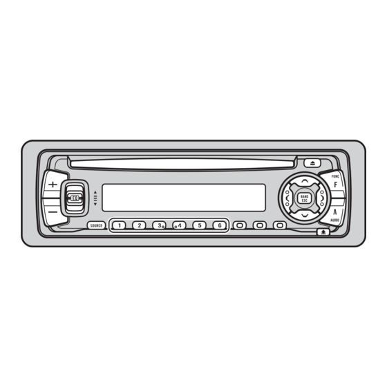
Page 64: Operations And Specifications
DEH-3130R,3100R-B,3100R 8. OPERATIONS AND SPECIFICATIONS 8.1 OPERATIONS 5/∞/2/3 buttons Disc loading slot EJECT button FUNCTION button +/– button AUDIO button BAND button DETACH button EQ button Buttons 1 – 6 DISPLAY button PTY button SOURCE button TA/NEWS button... - Page 65 DEH-3130R,3100R-B,3100R...
- Page 66 DEH-3130R,3100R-B,3100R...
- Page 67 DEH-3130R,3100R-B,3100R...
- Page 68 DEH-3130R,3100R-B,3100R...
-
Page 69: Specifications
DEH-3130R,3100R-B,3100R 8.2 SPECIFICATIONS General CD player Power source ..14.4 V DC (10.8 – 15.1 V allowable) System ........Compact disc audio system Grounding system ........Negative type Usable discs ..........Compact disc Max. current consumption ........10.0 A Signal format ....Sampling frequency: 44.1 kHz Dimensions Number of quantization bits: 16;...