Table of Contents
Advertisement
Advertisement
Table of Contents

Related Manuals for Motorola DCX3200 P2


Summary of Contents for Motorola DCX3200 P2
- Page 1 IN STALLAT ION MANUA L DCX3200 P2...
- Page 3 IMPORTANT SAFETY INSTRUCTIONS • Read these instructions. • Keep these instructions. • Heed all warnings. • Follow all instructions. • Do not use this apparatus near water. • Clean only with dry cloth. • Do not block any ventilation openings. Install in accordance with the manufacturer’s instructions. •...
- Page 4 • Consult the dealer or an experienced radio/TV technician for help. Caution: Changes or modifications not expressly approved by Motorola for compliance could void the user’s authority to operate the equipment. This device complies with part 15 of the FCC Rules. Operation is subject to the following two conditions: (1) This device may not cause harmful interference, and (2) this device must accept any interference received, including interference that may cause undesired operation.
- Page 5 © 2010 Motorola, Inc. All rights reserved. No part of this publication may be reproduced in any form or by any means or used to make any derivative work (such as translation, transformation, or adaptation) without written permission from Motorola, Inc.
-
Page 7: Table Of Contents
CONTENTS 1 Introduction .................................. 1 Features ..................................1 Tuners................................. 1 Standard Audio/Video Features........................2 Standard Data Features ..........................2 Standard Miscellaneous Features ........................ 2 Getting Help................................3 2 Overview ..................................5 Front Panel................................5 Rear Panel ................................5 M-Card™................................... 6 3 Installation .................................. - Page 8 General Status ............................... 34 Purchase Status ..............................36 Out-Of-Band (OOB) Status ........................... 37 Agile OOB Tuner Hunting............................38 Manual Selection of the OOB Frequency (OSD Frequency Override in Hunted Mode)...... 38 In-Band Status ............................... 39 Unit Address................................41 Separable Security..............................42 Current Channel Status ............................
-
Page 9: Introduction
Ethernet and Universal Serial Bus (USB) 2.0 ports for future home networking applications • Adaptability to various software platforms As with all Motorola digital cable set-tops, the hardware features are enabled by core operating and third-party application software. Figure 1-1 Front and Rear views Features Tuners •... -
Page 10: Standard Audio/Video Features
1 INTRODUCTION Standard Audio/Video Features • ITU standard 64/256 QAM/FEC/enhanced adaptive equalizer • DES based encryption/DCII (via inserted CableCARD™) access control • Out-of-band data receiver (70-130 MHz) 3.088 Mbps • Digital video scaling (picture in graphics) • Accelerated 2-D and 3-D graphics support in hardware •... -
Page 11: Getting Help
Motorola Online: http://businessonline.motorola.com The TSCC is available 24 hours a day, 7 days a week; in addition, Motorola Online offers a searchable solutions database, technical documentation, repair status, shipping information and low priority issue creation/tracking. For specific Toll-Free numbers when calling from outside of the United States, please refer to your product manual or our web page. -
Page 13: Overview
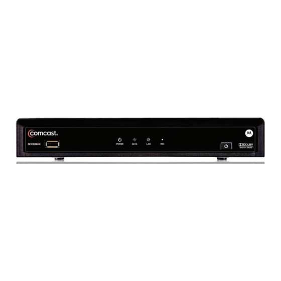
2 OVERVIEW Front Panel Figure 2-1 Front panel Table 2-1 Front panel USB connector* Power LED — Illuminates when the DCX3200 is powered on and blinks to indicate IR command received from remote control Data — Dual function LED • Flashes once per second to indicate unit is booting •... -
Page 14: M-Card
2 OVERVIEW Figure 2-2 Rear panel Table 2-2 Rear panel connections Cable In — Connects to cable signal from the service provider Ext IR Input – Connects to a remote control receiver accessory cable IEEE-1394 — Audio and video device connection M-Card —... -
Page 15: Installation
Verify that you have the necessary cables and other required items. Cold Reset Procedure This section describes the Cold Reset procedure for Motorola’s DCX3200 set-top. The cold reset is generally used by operational and field personnel to accomplish the following: •... -
Page 16: Video Connection Options
3 INSTALLATION Video Connection Options Use the following guidelines to determine the best video connection for the subscriber’s home entertainment system. To determine the available video inputs on the TV, check the manual supplied with the TV or the TV itself. The DCX3200 offers the following video outputs: Component HDTV and... -
Page 17: Audio Connection Options
This is important when the subscriber has another A/V device such as a DVD player, a secondary VCR, a CD player, or other electronic component. Motorola recommends connecting the TV to the monitor output so on-screen menus for the receiver can be displayed. -
Page 18: Connecting Hdtv - Single Connection For Video/Audio
3 INSTALLATION 1. Determine if you are connecting the audio to a home theater receiver or directly to the TV: • For an HDMI™ or IEEE-1394 video connection, no additional audio connections to the TV are required. • If the receiver or TV has a digital audio (S/PDIF) input, use the digital audio outputs. -
Page 19: Figure 3-1 Connecting The Dcx Set-Top To An Hdtv - Single Connection For Video/Audio
3 INSTALLATION Figure 3-1 Connecting the DCX Set-top to an HDTV — Single Connection for Video/Audio Because HDMI and IEEE-1394 provide both video and audio output, no additional audio connections to the TV are required if you use either of these connections. -
Page 20: Connecting Hdtv - Separate Video/Audio Connections
3 INSTALLATION Connecting HDTV — Separate Video/Audio Connections Cable In Connect an RF coaxial cable to the cable wall outlet and the Cable In connector on the DCX set-top. If the TV has a DVI input, use the DVI connection for the video: •... -
Page 21: Figure 3-2 Connecting The Dcx Set-Top To An Hdtv - Separate Video/Audio
3 INSTALLATION Figure 3-2 Connecting the DCX Set-top to an HDTV — Separate Video/Audio Note: If the receiver can check the baseband and digital audio (S/PDIF) ports for appropriate channels, connect both the baseband and digital audio connections. Otherwise, do not connect both the baseband left/right composite connections and the coaxial digital connection. -
Page 22: Connecting An A/V Receiver - Audio
3 INSTALLATION Connecting an A/V Receiver — Audio There are several options available for audio connections to the A/V receiver: • Digital audio (OPTICAL S/PDIF) • Digital audio (COAXIAL S/PDIF) • Stereo audio (AUDIO L and R) If the A/V receiver supports it, use the optical (S/PDIF) or coaxial (S/PDIF) audio outputs in place of the stereo audio outputs (AUDIO L and R). -
Page 23: Figure 3-3 Connecting The Dcx Set-Top To An A/V Receiver - Audio
3 INSTALLATION Figure 3-3 Connecting the DCX Set-top to an A/V Receiver — Audio Note: This connection method does not support HDTV. For information, see Connecting HDTV — Separate Video/Audio Connections in this section. -
Page 24: Connecting A Standard-Definition Tv (Sdtv)
3 INSTALLATION Connecting a Standard-Definition TV (SDTV) 1. Connect the stereo audio cable to the AUDIO L and R connectors on the DCX set- top and the AUDIO L and AUDIO R connectors on the Stereo TV (SDTV). 2. Connect a video cable to the VIDEO OUT connector on the DCX set-top and the INPUT VIDEO on the TV or an S-video cable to the S-VIDEO connectors on the DCX set-top and the TV. -
Page 25: Connecting A Standard-Definition Tv (Sdtv) And Vcr/Dvd Recorder
3 INSTALLATION Depending on the TV’s inputs: 1. If possible, use the S-Video and audio connections on the DCX set-top. 2. If the TV has no S-Video input, use the composite video and audio connectors on the DCX set-tops. Note: S-Video and Composite video require separate audio connections. Connecting a Standard-Definition TV (SDTV) and VCR/DVD Recorder 1. -
Page 26: Figure 3-5 Connecting The Dcx Set-Top To An A/V Receiver, Standard-Definition Tv (Sdtv), And Vcr/Dvd Recorder
3 INSTALLATION Figure 3-5 Connecting the DCX Set-top to an A/V Receiver, Standard-Definition TV (SDTV), and VCR/DVD Recorder... -
Page 27: Connecting An A/V Receiver, Tv, And Vcr
3 INSTALLATION Connecting an A/V Receiver, TV, and VCR 1. Connect a stereo audio cable to the AUDIO OUT L and R connectors on the DCX set-top and the INPUT L and R connectors on the A/V receiver. 2. Connect a video cable to the video out connector on the DCX set-top and the cable/TV video connector on the A/V receiver. -
Page 28: Figure 3-6 Connecting The Dcx Set-Top To An A/V Receiver, Standard-Definition Tv (Sdtv), And Vcr/Dvd Recorder
3 INSTALLATION Figure 3-6 Connecting the DCX Set-top to an A/V Receiver, Standard-Definition TV (SDTV), and VCR/DVD Recorder Note: Solid lines indicate optimum connections. Note: Because some entertainment equipment cannot simultaneously support baseband composite video and S-Video, never simultaneously connect both video inputs. -
Page 29: Data Device Connections
3 INSTALLATION Data Device Connections The DCX3200 provides optional high-speed data services such as Internet access, USB, Ethernet, and more. The functionality of each data device port requires, and depends on, installed application software. The DCX3200 rear panel provides the following data ports: USB 2.0 Can be used to daisy-chain USB devices such as printers and storage devices, or to interface with keyboards, joysticks, and other USB PC peripherals... -
Page 30: Operational Check For The Remote Control
When using an HDMI™ connection between the DCX3200 and the television, be sure to have the cable connected and the TV powered on before adjusting the video settings. Motorola recommends using certified Standard HDMI cables for 1080i or 720p resolutions and certified High Speed HDMI cable for a resolution of 1080p. - Page 31 3 INSTALLATION An example of the User Settings menu when the HDMI™ output is connected Note: The User Settings Menu indicates whenever an HDMI™ connection is in place between the DCX3200 and another device. When the HDMI™ connection is not being used, the User Settings Menu updates to reflect this: An example of the User Settings menu when the HDMI™...
- Page 32 3 INSTALLATION • Press the ▲ and ▼ keys to highlight the setting you wish to change. • Press the ► key to select an option. • To exit the setting and move to another setting, press the ▲ or ▼ key. If the User Settings menu does not display on the HDTV screen, the TV may not support the default video output setting.
- Page 33 3 INSTALLATION Setting Description HDMI/YPbPr The HDMI/YPbPr Output setting allows you to specify the video output Output format of the DCX3200 for all programs (when the 4:3 Override setting is set to Off or Stretch) or for all widescreen programs (when the 4:3 Override is set to 480i or 480p).
- Page 34 3 INSTALLATION Setting Description The 4:3 Override feature is available when the HDMI/YPbPr Output setting is 1080i, 720p, or 480p. My TV Supports The My TV Supports The Following Formats checklist allows you to The Following configure the Native mode operation of the DCX3200. The checklist Formats becomes accessible only when the HDMI/YPbPr Output setting is set to Native.
- Page 35 3 INSTALLATION Setting Description configured to provide video only in the 1080p30 and/or 1080p24 formats. The DCX3200 also does not support the 1080p60 video format. Note 5: The DCX3200 provides 480i format video on the YPbPr output whenever 1080p30 or 1080p24 format video is provided on the HDMI™ output.
- Page 36 3 INSTALLATION 1. With an HDMI™ connection in place, power off the DCX3200 and then immediately press the key on the remote control. This displays the main User Settings MENU menu. Move the cursor next to the “Additional HDMI Settings” option and press the ►...
- Page 37 3 INSTALLATION Setting Description Audio Output The Audio Output setting allows you to specify the digital audio format delivered over the HDMI™ connection by the DCX3200. Options include Auto, L-PCM, and Pass Through. By default, the Auto option is selected. The options are used as follows: •...
- Page 38 3 INSTALLATION An example of the Additional Closed Caption Settings menu The Additional HDMI™ Settings menu options are: Setting Description Service Sets the service used by the DCX3200 to render (draw) the closed captions: Selection • Analog: CC1, CC2, CC3, CC4, T1, T2, T3, or T4. The default is CC1. •...
-
Page 39: Graphics Overlaying The Video
3 INSTALLATION Setting Description Settings Sets the default settings for closed captions (AUTO) or the settings you have configured (USER). Defaults to AUTO. Options are AUTO or USER. Return To Main Selecting this option returns you to the main User Settings menu screen. Page Restore Closed To reset all of the Additional Closed Caption settings to their default values,... -
Page 41: Diagnostics
4 DIAGNOSTICS Diagnostics are displayed on the on-screen display (OSD). They confirm proper installation, including: • Checking error states and signal integrity. • Identifying the cable terminal on the network. • Verifying communications with the headend. For the diagnostics described in this section: •... -
Page 42: General Status
4 DIAGNOSTICS General Status This diagnostic displays system status information on the OSD. The information is updated each time the diagnostic is displayed. - Page 43 4 DIAGNOSTICS The General Status fields are: Field Description Error Error codes display on the OSD when an error occurs. If multiple errors occur, the last recorded error is displayed: Error Code Description EP00 No error EP01 Not connected EP03 DRAM error EP04 SRAM error...
-
Page 44: Purchase Status
4 DIAGNOSTICS Purchase Status This diagnostic displays the status of subscriber event purchases on the OSD. The information is updated each time this diagnostic is viewed: The Purchase Status fields are: Field Description Unsent The number of purchases in the DCX remaining to be polled. It can be an integer from 0 to 63. -
Page 45: Out-Of-Band (Oob) Status
4 DIAGNOSTICS Field Description Credit Total Credit used for purchase processing. Debit Total Debit used for purchase processing. Out-Of-Band (OOB) Status This diagnostic indicates the out-of-band control channel status on the OSD. The information is updated every 5 seconds. The Out-Of-Band Status fields are: Field Description Indicates the OOB tuner center frequency, from 70 to 130 MHz. -
Page 46: Agile Oob Tuner Hunting
4 DIAGNOSTICS Field Description When carrier lock has been established, displays an estimate of the carrier signal-to-noise ratio in dB, with an explanation: GOOD — Good value FAIR — Marginal signal level, check the signal POOR — Unusable signal INVALID — Invalid SNR value When carrier lock has been established, displays an estimate of the AGC as a percentage, with an explanation: GOOD —... -
Page 47: In-Band Status
4 DIAGNOSTICS 1. When in the OOB Receiver Status Diagnostic, press the MENU button on the remote control to enter the frequency selection mode. The OSD displays a new “MAN FREQ” line at the bottom of the screen, which indicates the last known carrier frequency. - Page 48 4 DIAGNOSTICS The In-Band Status fields are: Field Description Mode The values displayed on the OSD are: 64 QAM — 64 QAM digital channel 256 QAM — 256 QAM digital channel Carrier Lock Indicates whether the in-band receiver is locked to the carrier. If a digital carrier is not present, it indicates the carrier is not locked: Description Carrier locked...
-
Page 49: Unit Address
4 DIAGNOSTICS Unit Address This diagnostic displays the unit address of the CableCARD if inserted: The Unit Address fields are: Field Description TvPC Indicates whether the TvPC renewable security system is installed: Installed NO — TvPC is not installed (Note: the DCX3200 does not include a TvPC slot.) CableCARD YES —... -
Page 50: Separable Security
4 DIAGNOSTICS Field Description Serial The Host Serial Number is displayed on the Unit Address diagnostic screen. Number The DOCSIS, Ethernet, 1394, USB, and MAC addresses are stored in protected Addresses flash and displayed in hexadecimal. Separable Security This diagnostic displays information on the inserted M-CARD and CableCARD Interface with the DCX. -
Page 51: Current Channel Status
4 DIAGNOSTICS Field Description verify Host’s SIGN. • AUTH KEY FAILED if status is not bound because of failure to match AuthKey from the Host Device. • FAILED if binding failed for other reasons. Pairing Rpt Method Set to MMI or Reportback as received by a message from the headed, or set to Unknown if the headend message was not received. - Page 52 4 DIAGNOSTICS The Current Channel status fields are: Field Description Type Indicates whether the channel is analog or digital: Description DIGITAL Digital Status Indicates the current status of channel acquisition. Description Acquired Service has been acquired and is playing, but stream components may not be locked yet if the service is digital.
- Page 53 4 DIAGNOSTICS Field Description Service Service number from the secure processor. It is a one bit value; 0 or 1. Status Service status from the secure processor. It is a decimal value from 0 to 3. Service ID from the secure processor. It is a hexadecimal value. First 2 bytes indicate MPEG service number and the last byte indicates another unique identifier.
-
Page 54: Rf Modem (Upstream)
4 DIAGNOSTICS RF Modem (Upstream) This diagnostic displays the RF modem status, if an RF modem is installed in the DCX3200. The information is updated each time this diagnostic is displayed. The RF Modem fields are: Field Description Status CONFIGURED or NOT CONFIGURED. Center The RF modem center frequency is displayed on the OSD in MHz. - Page 55 4 DIAGNOSTICS The Code Modules fields are: Field Description Boot Code The boot code version in ASCII format. Platform Built The date platform software was built. Version The firmware version and build date in ASCII format. Processor The digital secure processor version in ASCII format. Analog The analog secure processor version in ASCII format.
-
Page 56: Memory Configuration
4 DIAGNOSTICS Field Description DIS-NOT RUN Disabled_Not_ Runnable Object is disabled and cannot DELETING Deleting Object is being deleted POSTPONED Postponed Object cannot run on the current system; it will be enabled during the next boot CONNECTED Connect Connected to download PID —... - Page 57 4 DIAGNOSTICS Field Description AUDIO S/PDIF Indicates S/PDIF Mode as set by application software. OSD Display Description Audio S/PDIF mode is not applicable. IEC958PCM PCM audio selected. ® ® Dolby Digital For Dolby Digital selection, the following speaker selection is set: right front or left front right front and left front right front and left front and center...
- Page 58 4 DIAGNOSTICS Field Description UNMUTED Displayed if mute method is not selected MUTE to Displayed if the mute method includes stopping video and presenting a still frame STILL (similar to a pause function) MUTE to Displayed if mute method presents a black screen BLACK Captions The captions mode displays captions present on the service...
- Page 59 4 DIAGNOSTICS Field Description Closed Caption service T 1 Closed Caption service T 2 Closed Caption service T 3 Closed Caption service T 4 Primary Lang Primary language established by the provider (default, Service 1) Second Lang Secondary language established by the provider (Service 2) Service 3 Set by the provider Service 3 Service 4...
-
Page 60: Interface Status
4 DIAGNOSTICS Interface Status The Interface Status diagnostic displays when running in Thin Client. The information on the OSD is updated when you display the diagnostic. - Page 61 4 DIAGNOSTICS...
- Page 62 4 DIAGNOSTICS The Interface Status fields are: Field Description DOCSIS Tuner & Xmitter Indicates if enabled; indicates if active 1394 I/O Device Indicates if enabled; indicates if active USB I/O Device Indicates if enabled; indicates if active Ethernet Device Indicates if enabled; indicates if active Parallel Port Indicates if enabled;...
-
Page 63: User Setting Status
4 DIAGNOSTICS Field Description EDID Data Indicates the video timing formats that were read from the Extended Display Identification Data (EDID) register for the connected device, in particular the detailed timing description blocks. The list displays all of the formats that the DCX3200 could read, up to a maximum of 12 formats. - Page 64 4 DIAGNOSTICS Setting Description format (1920 x 1080 pixels). • 720p — The DCX set-top presents programs in the High-Definition 720p format (1280 x 720 pixels). • 480p — The DCX set-top presents programs in the Enhanced-Definition 480p format (720 x 480 pixels). •...
-
Page 65: Docsis Status
4 DIAGNOSTICS Setting Description Type LEFT SHADOWED, or RIGHT SHADOWED. The default is AUTO. Font Edge Sets the edge color — AUTO, WHITE, BLACK, RED, GREEN, BLUE, YELLOW, Color MAGENTA, or CYAN. The default is AUTO. Background Sets the background color for closed captions. Defaults to AUTO. Options are Color AUTO, WHITE, BLACK, RED, GREEN, BLUE, YELLOW, MAGENTA, or CYAN. - Page 66 4 DIAGNOSTICS The fields are: Field Description DOCSIS For a DOCSIS-enabled set-top, YES. Otherwise, NO. Enabled Acquire DS The DOCSIS downstream channel acquisition status: Channel • YES — The downstream channel is acquired. • NO — The set-top is acquiring the downstream channel. •...
- Page 67 4 DIAGNOSTICS Field Description eCM Registered Displays whether the embedded cable modem has registered with the cable modem termination system (CMTS): • YES — DOCSIS registration is complete. • NO — DOCSIS registration is in progress, or the set-top could not register.
- Page 68 4 DIAGNOSTICS Field Description Mode The DOCSIS downstream channel modulation: QAM 64 or QAM 256. If the value is invalid or cannot be retrieved, Carrier Lock is NO, or if DOCSIS is not enabled, 000 is displayed. Power Level The downstream channel power level in dBmV. If the value is invalid or cannot be retrieved, Carrier Lock is NO, or if DOCSIS is not enabled, 000 is displayed.
-
Page 69: Application Specific Information
4 DIAGNOSTICS Application Specific Information This diagnostic displays information about application servers: The fields are: Field Description Server # Name The application server name of up to 14 alphanumeric characters. It is blank if the value is invalid or no value can be retrieved. Srvr # IP Addr The application server’s IP address in dotted-decimal format xxx.xxx.xxx.xxx;... - Page 70 4 DIAGNOSTICS The Interactive Status fields are: Field Description IP Address The IP address in dotted-decimal format xxx.xxx.xxx.xxx assigned by the NC 1500 to the DCX3200. 0.0.0.0 is displayed if the IP address is not configured or unknown. The upstream modem address value is the same as the terminal ID assigned by the DAC 6000.
- Page 71 4 DIAGNOSTICS Field Description INIT_STOPPED The DCX3200 is in the interactive initialization state and the TransMode has stopped. RUN_WAIT_DC_ The DCX3200 is in the interactive state and waiting for OR_C the default configuration or the contention channel list messages. RUNNING Interactive state is running, sending idle messages, and waiting for any prepare for poll or MAC messages.
-
Page 73: Troubleshooting
5 TROUBLESHOOTING Troubleshooting guidelines follow. If problems still occur after performing the diagnostics, call the TRC for assistance as described in the Introduction. Problem Possible Solution The DCX set- The DCX set-top may have received a software update and may not power on top will not while the new software is being installed. - Page 74 5 TROUBLESHOOTING Problem Possible Solution There is no Verify that the TV is powered on and set to the appropriate input source for the video on the DCX set-top. TV screen Verify that the DCX set-top is powered on and tuned to an authorized cable channel.
- Page 75 5 TROUBLESHOOTING Problem Possible Solution There are All 4:3 HDTVs display HD programs in letterbox format (black bars above and black bars below the picture) because of the shape of the display screen. above and • Turn on the 4:3 OVERRIDE feature in the User Settings menu. This below the enables most standard-screen TVs to display a full screen picture when picture...
- Page 77 Motorola, Inc. 101 Tournament Drive Horsham, PA 19044 U.S.A. http://www.motorola.com 571332-001-a 01/10...