Haier EA-1770EG Service Manual
Hide thumbs
Also See for EA-1770EG:
- Instructions for use manual (8 pages) ,
- Instrukcja obs?ugi (28 pages)
Advertisement
Table of Contents
- 1 Microwave Oven
- 2 Table of Contents
- 3 Contents
- 4 Model Identification
- 5 Product Code Illumination and Series Introduction
- 6 Specifications
- 7 Safety Precaution
- 8 Warning and Cautions
- 9 Installation and Accessory Parts
- 10 Parts and Functions
- 11 Maintenance Service and Trouble Shooting
- 12 Power Cord
- 13 Circuit Diagram and Circuit Explanation
- 14 Exploded View and List of Parts
- Download this manual
See also:
Instructions for Use Manual
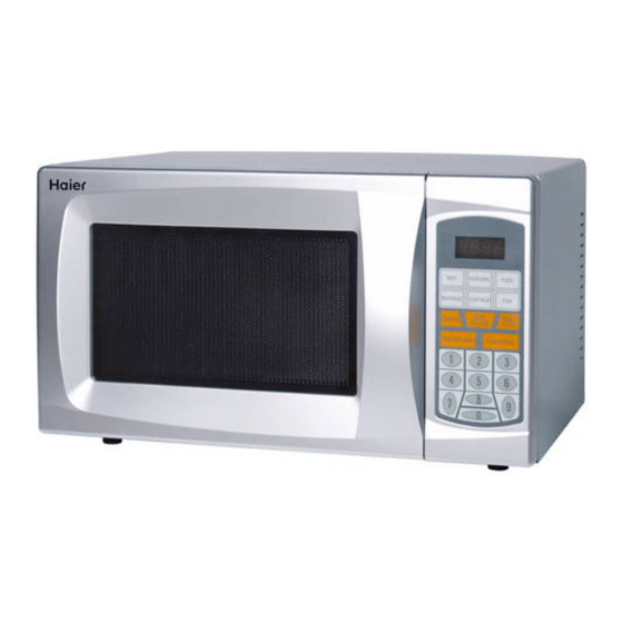
Microwave oven
SERVICE MANUAL
Features
Safe to use
The door adopts unique anti-choke structure and integrated punch forming, and thus
effectively prevents the microwave from leaking.
It is controlled by two-step interlock switch.The power will be switched off automatically
when the door is open,therefore it is much safer to use.
Shining appearance
The door shell and operation panel frame shell adopt imported high-quality stainless steel material,
and will never get rust and change color. It has modern appearance and superior quality,and thus
becomes the best choice for the household microwave oven.
High-temperature grill
It has two-step grill function ,and can grill food quickly and high-efficiently.It has
two-step''microwave+grill"combined grill function, and can produce perfect grill food.
Serial Number: 00505017702
MEAT
BEVERAGE
Defrost
MicroPower
Version:00.00
Models
PIZZA
FISH
EA-1770EG
Grill
Start
+30S
/Combi
Clear/Stop
EA-2080EG
1
2
3
4
5
6
8
9
7
0
Edition: 2005-11-16
Advertisement
Table of Contents

Related Manuals for Haier EA-1770EG


Summary of Contents for Haier EA-1770EG
-
Page 1: Microwave Oven
Microwave oven SERVICE MANUAL Models PIZZA MEAT FISH BEVERAGE EA-1770EG Grill Start Defrost +30S /Combi MicroPower Clear/Stop EA-2080EG Features Safe to use The door adopts unique anti-choke structure and integrated punch forming, and thus effectively prevents the microwave from leaking. -
Page 2: Table Of Contents
Contents Contents 1. Contents……………..…………………………………………………………………1 2. Product Code illumination and Series Introduction……………………...…...2 3. Specifications……..…………………………………………...………………….3 4. Safety Precaution…………………………………………..………………………4 5. Warning and Cautions……………………………………………………………..5 6. Installation and Accessory Parts…………………………………………………8 7. Parts and Functions………………………………………………………………..10 8. Maintenance Service and Trouble Shooting…………………………………...11 9. Circuit Diagram and Circuit Explanation………………………………………..23 10. -
Page 3: Model Identification
20 liter , the microwave output power consumption is 800 Watts. A appearance. EA-1770EG It represents made for Europe electronic microwave oven grill , the cavity capacity is 17 liter , the microwave output power consumption is 700 Watts. -
Page 4: Specifications
Specifications 3.Specifications Item Description Model EA-1770EG EA-2080EG Power source ¡ « 230V/50Hz ¡ « 230V/50Hz Input Power consumption 1200W 1300W output Power consumption 700W 800W Power consumption 1000W 1000W For grill Oscillating frequency 2450MHz Timing range 30’ Power level Unit Dimension 345¡... -
Page 5: Safety Precaution
Safety Precaution 4.Safety Precaution Only professional technicians can do the maintenance. Please refer to the proper maintenance procedures in the service manual for safe operations, so as to avoid unexpected injury. Points of attention during maintenance: 1. Do not operate the microwave oven while the door of the oven is open. 2. -
Page 6: Warning And Cautions
Warning and Cautions 5.Warning and Cautions Electric Attention Danger shock Warning dismantle hazard Do not use a metal rod to enter the interlock switch hole on the front side of the cavity. interlock switch hole Danger Danger Do not use sealed containers. For those Do not apply excessive force to the door. - Page 7 Warning and Cautions - 6 -...
- Page 8 Warning and Cautions POINTS OF ATTENTION Not like the other household appliances, the microwave oven is a kind of high-voltage appliance. Although common operations will not risk the user in hazard, please operate it carefully. 1. Do not use duplex receptacle in usage and maintenance. 2.
-
Page 9: Installation And Accessory Parts
Installation and Accessory Parts 6.Installation and Accessory Parts 6.1 Installation Do notinstall the microwave oven in an environment that is humid or with high temperature. attention Attention 6.2 key Point In Installation Adjustment Please read following before installation. 6.2.1 Install the microwave oven 1. - Page 10 blue wire to the wire marked with “N” or the black wire; connect the brown wire to the wire marked with “L” or the red wire. 6.3 Accessory parts Installation Environment Ventilation space is required in installation Do not install the microwave oven in environment that is humid or with high of the microwave oven.
-
Page 11: Parts And Functions
Parts and Functions 7.Parts and Functions name of part wave guide cover cavity Door contro panel hole of door hook door seal door hook baking mesh glass rotary tray tray support turn axis diagrammtic sketch for the accessory installation - 10 -... -
Page 12: Maintenance Service And Trouble Shooting
Maintenance Service and Trouble Shooting 8.Maintenance Service and Trouble Shooting 8.1SERVICE GUIDE AND REPLACING PARTS 8.1.1 Tools and gauges 8.1.2 Necessary tools 9.1.3 Necessary gauges Generally, the tools used in maintenance of (1) Universal meter the TVs are suitable for the maintenance of (2) Microwave leakage detector: the microwave oven. -
Page 13: Power Cord
Maintenance Service and Trouble Shooting measured part. 9.3 Installation and adjustment 8.2. Checking under decomposed condition A. Dismantle the shell In replacing the magnetron, after all the ¢ Ù Switch off the power. Parts are replaced and measured, and before ¢ Ú First loosen the rear screw. Take the shell is installed, check the energy leakage off the shell towards upper rear of the microwave oven. - Page 14 year. down hinge with cross screwdriver. Maintenance Service and Trouble Shooting ¢ Ú P ull up the door towards you to take off it. Attention: After installation of the oven door, please check if the first/second lockout switch and monitoring switch work well. After oven door is installed, check the leakage with leakage detector.
- Page 15 Maintenance Service and Trouble Shooting Attention: Be sure to discharge the high-voltage capacitor to do dismantling immediately after working. H: Dismantling of the duct and lamp (1) Cut off the connecting wire of the lamp (2) Loosen the screw fixing the duct and the magnetron (3) Open the hook at the middle of the duct connecting to the magnetron installation board with a screwdriver...
- Page 16 Maintenance Service and Trouble Shooting (3) Take off the timer from the rear of the switch on the computer board. control panel. (3) Take off the computer board from the rear of the control panel. L: Dismantling of the lockout device 1.
- Page 17 Maintenance Service and Trouble Shooting switches: When the door is open, the first/second lockout switch is off. The monitoring switch is on. When the door is close, the switches are in counter mode. You can observe by sight. If you are not sure, please measure with gauges. In maintenance, pull the door with hands as slowly as possible to see if the microswitches act in following turn: in opening: the first lockout switch –...
- Page 18 Maintenance Service and Trouble Shooting Item Position Normal value Resistance value Two ends of the heater About less than 1¦ ¸ End and shell of the Infinite heater Attention: In test of the magnetron, confirm that the gasket is in good condition and installed well.
- Page 19 Maintenance Service and Trouble Shooting The resistance value of the two terminals shall be 14k~15kohm H. Measurement of the AK rectifier Under normal condition, it is infinite to measure in two condition. Attention: If the fuse is burned out, it is probably breakdown by the AK rectifier.
- Page 20 FILTER FUSE L(OUT) L(IN) FILTER 1.5mH 2200P/400 N(OUT) N(IN) 0.33UF/275 2200P/400V DELAY CIRCUIT relay R1 100¦ ¸ TAPI - 19 -...
- Page 21 Maintenance Service and Trouble Shooting 8.5. Trouble-Shooting In case that there are complaints from the customers, please study the reported troubles carefully. For the problems listed below, please introduce the proper usage to the customers to avoid necessary troubles. Attention: (1) Please first check the installation of the earth wire before trouble-shooting.
- Page 22 . Maintenance Service and Trouble Shooting Trouble 1The oven works normally, but the heating is too slow. (1).the output power consumption is too small Check the power voltage: If 90% lower than the normal voltage, the voltage is too low, adjust the power supply.
- Page 23 Maintenance Service and Trouble Shooting abnormal ,replaced it. If normal, Replace the fuse ,cut off the connection wire between the transformer and the high-voltage capacitor ,then start the oven .If normal, the AK rectifier ,is bad, replace it. The fuse is not broken Check the conduction of the thermostat1and thermostat2,if wrong, replace it.
-
Page 24: Circuit Diagram And Circuit Explanation
Circuit Diagram and Circuit Explanation 9.Circuit Diagram and Circuit Explanation (in) (out) DELAY CIRCUIT (in) (out) Circuit description: 1. The Plug L(B)&N(G) is used to supply power for the control panel, at the same time offers the access for the lamp, the tray motor and the fan motor. 2. -
Page 25: Exploded View And List Of Parts
Circuit Diagram and Circuit Explanation Magnetron 230 50Hz Rectifier 1. After the oven start working, a 230V AC voltage is added between the two ends of the high-voltage transformer. 2. The 230V voltage will make 2000V induction voltage between the two ends of the high-voltage coil, and 3.5V low-voltage between the two ends of the heater winding. - Page 26 Microwave Oven Model: EA-1770EG KNOCK-DOWN DRAWINGS FOR INDOOR UNIT Exploded View(EA-1770EG)
- Page 27 HET PRICE Parts code parts name (Euro) Remarks 0050600036 ST4*10BOLT 0050100528 OUTER CASING 0050600022 M3*6 BOLT 0050801530 CAVITY ASSY 0050400710 FILTER 0050400373 FAN MOTOR 004HR2501G ST4*19 BOLT 0050600036 ST4*10 BOLT 0050201495 FLARE 0050201517 FAN 0057100103 MAGNETRON 0050600036 ST4*10 BOLT 0050201492 CHAIN-SWITCH HOLDER GROUP 0050400605 MOCROMOTION SWITCH 0050400604 MOCROMOTION SWITCH...
- Page 28 0050300098A OUTER SCREEN 0050201570 DOOR CASE 0050400385 POWER SUPPLY CORD 0050400709 WIRING HARNESS 0057109123 M3*6 BOLT 0050400489 THERMOSTAT 0050400480 AK rectifier 0056200109 LAMP 0050600033 ST4*8 BOLT 0050100288 QUARTZ HEARTER HOLDER 0050400476 GRILL HEATER 0050400491 THERMOSTAT...
- Page 29 Exploded View(EA£ - 2080EG) - 28 -...
- Page 30 45 46 53 54 - 29 -...
- Page 31 EA-2080EG LIST OF PART Parts code parts name QTY HET PRICE (Euro) Remarks 0050300121 WAVE GUIDE COVER 0050600033 ST4*8BOLT 0050900056 GLASS TRAY 0050200532 TURNPLATE-BRACKET GROUPWAREGL 0050200531 TURN AXIS 0057100104 HV-CAPACITOR 0050400479 H.V. DIODE 0050600022 ST4*10 BOLT 0050100273 HV-CAPACITOR HOLDER 0050400480 AK rectifier 0054500063 HV-TRANSFORMER 0056201102...
- Page 32 0050600036 ST4*8 BOLT 0050200469 CHAIN-SWITCH HOLDER GROUP 0050400604 MOCROMOTION SWITCH 0050600027 DOOR-HOOK SPRING 0050200470 DOOR-HOOK 0057109123 ST3*8 BOLT 0050400489 THERMOSTAT 0050400622 MAGNETRON 0050600036 ST4*8 BOLT 0050201571 0050200467 FLARE 0050600036 ST4*10 BOLT 0050400373 FAN MOTOR 004HR2501G ST4*19 BOLT 0050400394 FILTER 0050600030 ST3*5 BOLT 0050200471 DOOR SEAL 0050200525...
- Page 33 Microwave oven Model: EA-1770EG Sincere Forever Haier Group Haier Industrial Park, No.1, Haier Road 266101, Qingdao, China http://www.haier.com...