Table of Contents
Advertisement
Available languages
Available languages
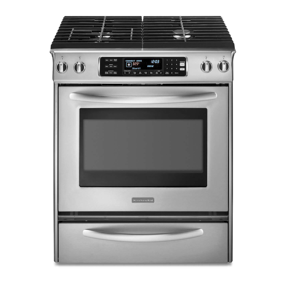
INSTALLATION INSTRUCTIONS
30" (76.2 CM) FREESTANDING AND SLIDE-IN
DUAL FUEL RANGES
INSTRUCTIONS POUR L'INSTALLATION DES
CUISINIÈRES AUTOPORTANTES ET
ENCASTRABLES À BI-COMBUSTIBLE
DE 30" (76,2 CM)
Table of Contents/Table des matières..................................................................................2
IMPORTANT:
Save for local electrical inspector's use.
Installer: Leave installation instructions with the homeowner.
Homeowner: Keep installation instructions for future reference.
IMPORTANT :
À conserver pour consultation par l'inspecteur local des installations électriques.
Installateur : Remettre les instructions d'installation au propriétaire.
Propriétaire : Conserver les instructions d'installation pour référence ultérieure.
W10118264A
Advertisement
Table of Contents

Related Manuals for KitchenAid DUALFUEL RANGES


Summary of Contents for KitchenAid DUALFUEL RANGES
-
Page 1: Installation Instructions
INSTALLATION INSTRUCTIONS 30" (76.2 CM) FREESTANDING AND SLIDE-IN DUAL FUEL RANGES INSTRUCTIONS POUR L’INSTALLATION DES CUISINIÈRES AUTOPORTANTES ET ENCASTRABLES À BI-COMBUSTIBLE DE 30" (76,2 CM) Table of Contents/Table des matières...2 IMPORTANT: Save for local electrical inspector's use. Installer: Leave installation instructions with the homeowner. Homeowner: Keep installation instructions for future reference. -
Page 2: Table Of Contents
TABLE OF CONTENTS RANGE SAFETY ...2 INSTALLATION REQUIREMENTS ...4 Tools and Parts ...4 Location Requirements...4 Electrical Requirements - U.S.A. Only ...7 Electrical Requirements - Canada Only...8 Gas Supply Requirements ...8 Countertop Preparation ...9 INSTALLATION INSTRUCTIONS ...10 Unpack Range...10 Measure for Proper Height...10 Adjust Leveling Legs ...11... - Page 3 If using a ball valve, it shall be a T-handle type. A flexible gas connector, when used, must not exceed 3 feet. A child or adult can tip the range and be killed. Connect anti-tip bracket to rear range foot.
-
Page 4: Installation Requirements
5" (12.7 cm) beyond the bottom of the cabinets. All openings in the wall or floor where range is to be installed must be sealed. Do not seal the range to the side cabinets. - Page 5 Contact a qualified floor covering installer to check that the floor covering can withstand at least 200°F (93°C). Use an insulated pad or ¼" (0.64 cm) plywood under range if installing range over carpeting. IMPORTANT: Some cabinet and building materials are not designed to withstand the heat produced by the oven for baking and self-cleaning.
- Page 6 30" (76.2 cm) minimum clearance between the top of the cooking platform and the bottom of an unprotected wood or metal cabinet. If installing a range hood or microwave hood combination above the range, follow the range hood or microwave hood combination installation instructions for dimensional clearances above the cooktop surface.
-
Page 7: Electrical Requirements - U.s.a. Only
A UL listed conduit connector must be provided at each end of the power supply cable (at the range and at the junction box). Wire sizes and connections must conform with the rating of the range (40 amps). -
Page 8: Electrical Requirements - Canada Only
This range is design-certified by CSA International for use with Natural gas or, after proper conversion, for use with LP gas. This range is factory set for use with Natural gas. See “Gas Conversions” section. The model/serial rating plate located on the right side oven door trim has information on the types of gas that can be used. -
Page 9: Countertop Preparation
½ psi (3.5 kPa). The cooktop sides of the slide-in range fit over the cutout edge of your countertop. If you have a square finish (flat) countertop and the opening width is 30"... -
Page 10: Installation Instructions
Keep cardboard bottom under range. Remove oven racks and parts package from inside oven. 2. To place range on its back, take 4 cardboard corners from the carton. Stack one cardboard corner on top of another. Repeat with the other 2 corners. Place them lengthwise on the floor behind the range to support the range when it is laid on its back. -
Page 11: Adjust Leveling Legs
1. If range height adjustment is necessary, use a wrench or pliers to loosen the 4 leveling legs. This may be done with the range on its back or with the range supported on 2 legs after the range has been placed back to a standing position. -
Page 12: Remove Warming Drawer
Remove Warming Drawer Remove the warming or storage drawer to gain access to the lower section of the range. This will be necessary for some of the following installation steps. To Remove Warming Drawer: 1. Open drawer to its fully open position. -
Page 13: Electrical Connection - U.s.a. Only
Failure to follow these instructions can result in death, fire, or electrical shock. 1. Disconnect power. 2. Remove the terminal block cover screws located on the back of the range. Pull cover down and toward you to remove cover. A. Hold-down screws B. Terminal block cover 3. - Page 14 1. Remove the ground-link screw from the range frame. Save the ground link screw and cup washer. Bend the ground-link away from the range so that it does not contact the range. 2. Connect the green ground wire from the power supply cord to the range using the ground-link screw.
- Page 15 In an area where local codes prohibit grounding through the neutral 1. Remove the ground-link screw from the range frame. Save the ground-link screw and cup washer. Bend the ground-link away from the range so that it does not contact the range. 1" (2.5 cm) 3"...
-
Page 16: Make Gas Connection
2. Connect the bare ground wire to the range using the ground- link screw and cup washer. The ground wire must be attached first and must not contact any other terminal. A. Bare wire from power E. Line 2 supply cable F. -
Page 17: Electronic Ignition System
½" male pipe thread) Freestanding Ranges Slide-In Ranges 5. Plug in range or reconnect power. “Clock-Enter Time” should appear in the display. For further information, please refer to the user instructions located in the Use and Care Guide. Initial lighting and gas flame adjustments Cooktop burners use electronic igniters in place of standing pilots. -
Page 18: Replace Oven Racks And Warming Drawer
If burners do not light properly: Turn cooktop control knob to the “OFF” position. Check that the range is plugged in and the circuit breaker has not tripped or the household fuse has not blown. Check that the gas shutoff valves are set to the “open”... -
Page 19: Gas Conversions
Electrical supply is connected. See “Troubleshooting” in the Use and Care Guide. When the range has been on for 5 minutes, check for heat. If range is cold, turn off the range and contact a qualified technician. - Page 20 9. Reinstall the cap onto the regulator. A. Access cap D. Spring retainer B. Gasket E. Spring retainer C. Gas pressure regulator To Convert Standard Surface Burners 1. Remove burner cap. 2. Using a T20 TORX ® screwdriver, remove the burner base. 3.
-
Page 21: Natural Gas Conversion
Natural Gas Conversion WARNING Tip Over Hazard A child or adult can tip the range and be killed. Connect anti-tip bracket to rear range foot. Reconnect the anti-tip bracket, if the range is moved. Failure to follow these instructions can result in death or serious burns to children and adults. - Page 22 4. Gas orifice spuds are stamped with a number on the side. Replace the LP gas orifice spud with the correct Natural gas orifice spud. A. Stamped number Refer to the following chart for the correct Natural gas orifice spud placement. Natural Gas Orifice Spud Chart for Standard Surface Burners Burner Location Burner Rating...
-
Page 23: Sécurité De La Cuisinière
SÉCURITÉ DE LA CUISINIÈRE Votre sécurité et celle des autres est très importante. Nous donnons de nombreux messages de sécurité importants dans ce manuel et sur votre appareil ménager. Assurez-vous de toujours lire tous les messages de sécurité et de vous y conformer. Voici le symbole d’alerte de sécurité. -
Page 24: Exigences D'installation
EXIGENCES D’INSTALLATION Outillage et pièces Rassembler les outils et pièces nécessaires avant de commencer l'installation. Lire et suivre les instructions fournies avec les outils indiqués ici. Outillage nécessaire Mètre-ruban Ruban de masquage Tournevis à lame plate Composé d'étanchéité des raccords filetés - résistant Tournevis Phillips au propane Niveau... - Page 25 Respecter les dimensions indiquées pour la cavité d'installation entre les placards. Ces dimensions tiennent compte des valeurs minimales des dégagements de séparation. La bride antibasculement doit être installée. Pour l'installation de la bride antibasculement fournie avec la cuisinière, voir la section “Installation de la bride antibasculement”.
- Page 26 Les dimensions de l'espace d'installation entre les placards correspondent à une installation entre des placards de 24" (61 cm) avec plan de travail de 25" (64 cm) à hauteur de 36" (91,4 cm). Cuisinières autoportantes A. 18" (45,7 cm) entre le placard supérieur et le plan de travail B.
-
Page 27: Spécifications De L'installation Électrique
Spécifications de l’installation électrique AVERTISSEMENT Risque de choc électrique Relier la cuisinière à la terre. Le non-respect de cette instruction peut causer un décès, un incendie ou un choc électrique. Si le code en vigueur le permet et qu’un conducteur distinct de liaison à... -
Page 28: Préparation Du Plan De Travail
Canalisation de gaz Installer une canalisation de gaz rigide de ¾" (1,9 cm) jusqu'à l'emplacement d'installation de la cuisinière. L'emploi d'une canalisation de plus petit diamètre ou plus longue peut susciter une déficience du débit d'alimentation. On doit utiliser un composé d’étanchéité des tuyauteries résistant à l’action du gaz de pétrole liquéfié. -
Page 29: Instructions D'installation
INSTRUCTIONS D'INSTALLATION Déballage de la cuisinière AVERTISSEMENT Risque du poids excessif Utiliser deux ou plus de personnes pour déplacer et installer la cuisinière. Le non-respect de cette instruction peut causer une blessure au dos ou d'autre blessure. 1. Ôter les matériaux d'emballage, le ruban adhésif et le film protecteur de la cuisinière. -
Page 30: Installation De La Bride Antibasculement
REMARQUE : Pour placer à nouveau la cuisinière en position verticale, placer un carton ou un panneau de fibres dur devant la cuisinière. En utilisant au moins 2 personnes, relever la cuisinière et la placer sur le carton ou le panneau de fibres dur. -
Page 31: Retrait Du Tiroir-Réchaud
10. En cas d'installation de la cuisinière dans une résidence mobile, il est impératif de fixer la cuisinière au sol. Toute méthode de fixation de la cuisinière est adéquate dans la mesure où elle satisfait aux normes indiquées dans la section “Exigences d'emplacement”. -
Page 32: Système D'allumage Électronique
2. Utiliser une clé pour serrer tous les raccords entre la cuisinière et la canalisation de gaz. A. Tuyau de gaz de ½" ou ¾" G. Raccord B. Robinet d'arrêt manuel H. Mamelon C. Mamelon I. Coude à 90° (avec D. -
Page 33: Réinstallation Des Grilles Du Four Et Du Tiroir-Réchaud
Contrôle du fonctionnement des brûleurs de la table de cuisson Brûleurs standard de la table de cuisson Pousser et tourner le bouton de commande du brûleur à la position “LITE”. Les flammes doivent s'allumer sur le brûleur en moins de 4 secondes. -
Page 34: Achever L'installation
1. Vérifier que toutes les pièces sont maintenant installées. S'il reste une pièce, passer en revue les différentes étapes pour découvrir laquelle aurait été oubliée. 2. Vérifier la présence de tous les outils. 3. Jeter ou recycler tous les matériaux d’emballage. 4. - Page 35 2. Débrancher la cuisinère ou déconnecter la source de courant électrique. A. Vers la cuisinière B. Robinet d’arrêt manuel - manette à la position de fermeture C. Canalisation de gaz 3. Retirer le tiroir-réchaud. Voir la section “Retrait du tiroir- réchaud”...
- Page 36 Conversion pour un brûleur à flamme TripleTier certains modèles) 1. Enlever le chapeau de brûleur. 2. Utiliser un tournevis TORX ® T20 pour enlever la tête du brûleur. 3. Enlever la plaque associée au gicleur externe. A. Chapeaux de brûleur B.
-
Page 37: Conversion Pour L'alimentation Au Gaz Naturel
Conversion pour l'alimentation au gaz naturel AVERTISSEMENT Risque de basculement Un enfant ou une personne adulte peut faire basculer la cuisinière ce qui peut causer un décès. Joindre la bride antibasculement au pied arrière de la cuisinière. Joindre de nouveau la bride antibasculement si la cuisinière est déplacée. - Page 38 4. Chaque gicleur est marqué d'un chiffre gravé sur le côté. Remplacer le gicleur pour propane par le gicleur correct pour gaz naturel. A. Chiffre gravé Le tableau qui suit permet de sélectionner le gicleur pour gaz naturel correct pour chaque brûleur. Gicleurs pour gaz naturel pour brûleurs standard de la table de cuisson Position du brûleur...
-
Page 39: Anti-Tip Bracket Template
ANTI-TIP BRACKET TEMPLATE GABARIT POUR LA BRIDE ANTIBASCULEMENT Cut here and place top edge against the left side cabinet and right edge against rear wall. Couper ici et placer le rebord supérieur contre le côté gauche du placard et le rebord droit contre la paroi arrière. Holes in bracket Trous dans la bride... - Page 40 © 2007. All rights reserved. ® Registered Trademark/TM Trademark of KitchenAid, U.S.A., KitchenAid Canada licensee in Canada Printed in U.S.A. Tous droits réservés. ® Marque déposée/TM Marque de commerce de KitchenAid, U.S.A., Emploi sous licence par KitchenAid Canada au Canada Imprimé aux É.-U.